Table of Contents
Advertisement
Quick Links
Advertisement
Chapters
Table of Contents

Related Manuals for Texas Instruments TravelMate 2000


Summary of Contents for Texas Instruments TravelMate 2000
- Page 1 Texas Instruments TravelMate 2000 Notebook Computer User’s Manual...
-
Page 2: Table Of Contents
Contents Preface... v Taking a First Look The Hardware... 1-3 TravelMate 2000 Options...1-7 The Software... 1-10 The Hard Disk... 1-11 More About Hardware LCD Screen... 2-3 Right Side Panel...2-6 Left Side Panel... 2-7 Rear Panel... 2-9 Bottom Panel... 2-11 Front Panel... 2-12 Keyboard ... - Page 3 5 Application Programs Guidelines for Installing Applications ...5-3 LapLink...5-10 Laptop Manager ...5-13 Using the Password Utility...5-15 6 TravelMate 2000 Options Add-On Battery Pack ...6-2 3.5-inch Floppy Drive Unit...6-5 Numeric Keypad ...6-10 RAM Card External Monitor...6-18 2400 BPS Modem with Send-Fax and MNP Class 5...6-19...
- Page 4 Ms or her business. TravelMate and BatteryPro are trademarks of Texas Instruments incorporated. BitCom and BitFax are trademarks of BIT Software, Inc. Hayes is a registered trademark and Hayes SmartModem 2400 B is a trademark of Hayes Microcomputer Products Inc.
-
Page 5: Preface
The TravelMate 2000 is a lightweight, full-function computer with the features and power of many desktop personal computers, including a 20-megabyte internal hard disk drive, an 80C286 microprocessor, built-in MS-DOS transfer utility that connects your TravelMate 2000 to another computer, and many options to make your TravelMate 2000 more powerful and specialized for your particular applications. - Page 6 LapLink Cable LapLink File Transfer Utility and Device Driver User’s Manual MS-DOS User’s Manual BatteryPro Two Function Key template strips If any of the above items are missing, contact your Texas Instruments dealer. and Productivity Software User’s Manual and floppy diskette...
- Page 7 This symbol indicates a Note concerning operating procedures or information you should know to help you operate your TravelMate 2000. This symbol alerts you to a Warning or Caution that can prevent you from causing injury to yourself or damage to your equipment.
-
Page 8: About This Manual
Chapter 1 - Taking A First Look gives users who are not familiar with computers some basic information about the parts of a computer and a simple technical overview of the TravelMate 2000 and its options. Experienced users may only need to skim this chapter. -
Page 9: Specifications
80C287 12 MHz Coprocessor, external keyboards, CRT monitors, and printers. Appendix A -Specifications lists operating and environmental specifications for your TravelMate 2000. Appendix B - Taking Care of Your Computer provides information for cleaning your TravelMate 2000, as well as caring for your battery and conserving battery power. -
Page 10: Bios Messages
Preface Appendix G - BIOS Messages lists the error messages you may encounter and what to do about them. Appendix H - Configuring Memory illustrates the TravelMate 2000's memory map and describes the memory options of the computer. Appendix I - Connector Pin Assignments lists the signals produced by the standard and optional connectors on the TravelMate 2000. - Page 11 Troubleshooting and general care of the computer Chapter 1 and Appendices Other Manuals About the TravelMate 2000 The following manuals are furnished with your new TravelMate 2000 to help you operate and maintain your computer and its optional devices. Title...
-
Page 12: Taking A First Look
This chapter tells you about: Computer hardware such as the system main circuit board, the display, and the keyboard Options for your TravelMate 2000 Software operating systems and application programs Caring for the Hard Disk Contents The Hardware...1-3 System Board...1-4 Microprocessor ...1-4... - Page 13 Contents The Software...1-10 The Hard Disk ...1-11 Hard Disk Format...1-11 Taking Care of the Hard Disk...1-11 1-2 Taking a First Look...
-
Page 14: The Hardware
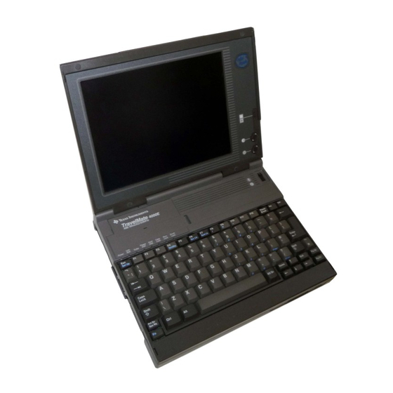
The Hardware This is what the standard TravelMate 2000 Computer looks like when it is closed. Here's how the TravelMate 2000 looks when it is set up and ready to operate. Taking a First Look 1-3... -
Page 15: System Board
A byte is a group of eight bits, and represents a single character or number, such as "H" or "9". The microprocessor in the TravelMate 2000 is a high-speed 80C286 microprocessor, running at a clock speed of up to 12 MHz. -
Page 16: Ram
(bytes) it can store. Symbols often used for this are "K" and "M". One K byte 1 K byte) represents 1024 bytes and one M byte (1 M byte) represents 1024 K bytes. The TravelMate 2000 has a standard RAM size of 1 M byte. -
Page 17: Lcd Screen
The TravelMate 2000's LCD screen can be set to emulate industry standard display modes, including the VGA mode used by IBM in its latest PS/2 series of personal computers, and displays colors as 16 shades of gray. -
Page 18: Travelmate 2000 Options
TravelMate 2000 Options The following hardware options are available from your Texas Instruments dealer or TI-Express, 1-800-TI-PARTS, for use with the standard TravelMate 2000 to expand its capabilities. See Chapter 6 for information about installing these options. Add-On Battery Pack (TI Part No. 2568030-0001) 1.44 M byte 3.5-inch Floppy Drive Unit (TI Part No. -
Page 19: Add-On Battery Pack
Add-On Battery Pack Attaching the optional Add-On Battery Pack to the rear of the TravelMate 2000 adds 3 hours to the operating time. When the Add-On Battery Pack is installed, you cannot use the 3.5-inch Floppy Drive Unit or the Expansion Unit. -
Page 20: Crt Adaptor
Printers Connecting a printer to your TravelMate 2000 allows you to produce a hard copy of information you have created. To connect a parallel printer, use the supplied conversion adaptor between the parallel port and the TravelMate 2000 printer port. -
Page 21: The Software
An application program is software that helps you perform business and personal tasks such as word processing, spreadsheet analysis, and graphics presentations. Almost all of the application programs written to run with MS-DOS on IBM and compatible personal computers can be used with the TravelMate 2000. 1-10 Taking a First Look... -
Page 22: The Hard Disk
Taking Care of the Hard Disk The hard disk in your TravelMate 2000 computer is specially designed to withstand the rigors of travel: the hard disk heads automatically park themselves when the computer is turned off. However, it is still a precision device and careful treatment will prolong its life. - Page 23 Then move the computer to the new location. This ensures that the hard disk mechanisms have time to adjust to the new environment and prevents moisture from condensing on the vital parts. In case of a hard disk failure, contact Texas Instruments at 1-800-847-5757 for information about data recovery.
-
Page 24: More About Hardware
This chapter tells you about: Your LCD screen and how to adjust it Controls and connectors on the sides of the TravelMate 2000 case Common keyboard key assignments Indicators and their meanings Contents LCD Screen ...2-3 Resolution...2-3 Screen Angle...2-4 Backlight...2-4 Standard/Reverse Switch...2-4... - Page 25 Contents Keyboard ...2-13 Enter Key...2-14 Shift ...2-14 Caps Lock...2-14 Tab ...2-15 Backspace...2-15 Ctrl ...2-15 Alt ...2-15 Alt Gr...2-15 Fn ...2-15 Cursor Control Keys...2-16 Esc ...2-16 Function Keys...2-16 Ins (Insert)...2-16 Del (Delete) ...2-17 Num Lk...2-17 Scr Lk ...2-17 Pause ...2-17 Break ...2-17 Sys Rq ...2-17 SC...
-
Page 26: Lcd Screen
Hardware Installation screen and the display mode your application program is designed to use. The display adaptor in the TravelMate 2000 allows you to select display modes for the LCD screen. (See the Hardware Installation Screen described in Chapter 4.) -
Page 27: Screen Angle
Appropriate angles are 90' to 132' from horizontal. Caution: when the screen is closed with the power on. The TravelMate 2000 is designed so that it can be used with the screen closed, for Instance, when running a demonstration program with an external monitor. -
Page 28: Contrast Control
Contrast Control The Contrast Control adjusts the contrast between the displayed information and the background for the best viewing condition. Use in conjunction with the Brightness Control. Brightness Control The Brightness Control adjusts the brightness of the illuminated display. Use in conjunction with the Contrast Control. -
Page 29: Right Side Panel
Right Side Panel The right side panel on the computer contains the numeric keypad connector and the security hook holder, as shown and described below. Numeric Keypad Connector The Numeric Keypad connector connects the optional Numeric Keypad to your computer. Note: the underside of the Numeric Keypad while the connector is in use. -
Page 30: Left Side Panel
There are two connectors and a slide switch on the left side panel of the computer, as illustrated and described below. Caution: Connections and settings made on the left side of the computer must be done with the power off. Parallel (Printer) Port You can connect a printer or other device that uses a standard Centronics parallel interface to the TravelMate 2000 via the supplied conversion adaptor. -
Page 31: Lcd/Crt Switch
Left Side Panel LCD/CRT Switch The TravelMate 2000 can display on either the standard LCD screen or on an external VGA monitor connected to the optional CRT Adaptor. Set the LCD/CRT switch appropriately. When the switch is set to CRT with the optional CRT Adaptor installed, the computer LCD screen is off. Always change the switch setting with the power off. -
Page 32: Rear Panel
Expansion Bus Connector The optional Floppy Drive Unit or the optional Expansion Unit plugs into the expansion bus connector on the rear of the TravelMate 2000. For details, see Chapter 6. Add-On Battery Pack Connector The optional Add-On Battery Pack plugs into the Battery pack connector. For details, see Chapter 6. -
Page 33: Ac Adaptor Jack
Chapter 3 for instructions on how to recharge the battery. Caution: Use only the supplied AC Adaptor with your TravelMate 2000 Computer. Other adaptors may not match the power requirements of the TravelMate 2000 and can cause serious damage to the system. -
Page 34: Bottom Panel
Bottom Panel Battery Slot The bottom panel of the computer has a slot for the supplied internal battery. For battery installation instructions, see Chapter 3. More About Hardware 2-11... -
Page 35: Front Panel
Front Panel The front panel of the computer has a power switch, an optional card slot cover, a keyboard, and eight indicators. Power Switch The power switch turns the power to the computer on and off for both battery-powered and ac operation. Set the switch to the I position to turn on the computer and to the Optional Card Slot Cover A cover for the optional card slot is located on the rear left of the front panel. -
Page 36: Keyboard
The TravelMate 2000 keyboard provides all the functions of the IBM enhanced keyboard. Many of the keys on the keyboard are similar to those on a standard typewriter. There are some keys, however, that might not be familiar to you. The following is a description of keys not found on a standard typewriter. -
Page 37: Enter Key
Keyboard Enter Key The Enter key is generally used to end a line or menu entry and move to the next one; also referred to as the Return key. Shift There are two identical Shift keys. Any alphanumeric key pressed while the Shift key is held down gives that key's uppercase character or the symbol on the top of the keytop. -
Page 38: Tab
The Tab key works like the tab key on a regular typewriter. Pressing the Shift key with the Tab key allows you to backtab. Backspace ( (Backspace) key moves the cursor to the left one space at a time, erasing the character to the left of the cursor. -
Page 39: Cursor Control Keys
Keyboard Cursor Control Keys The four arrow keys move the cursor by spaces or lines in The Fn key shifts the functions of these keys to Home, End, PgUp, and PgDn. These cursor and screen control functions may vary according to the software application. Refer to your software application manual for use of these keys. -
Page 40: Del (Delete)
Del (Delete) The Del (Delete) key is used to delete the character at the cursor position. In MS-DOS and many applications, remaining characters usually move left to fill the space. Num Lk The Num Lk key (Fn - Ins) toggles the numeric keypad keys on and off. When the Num Lk key is on, the Num Lock indicator is lit. -
Page 41: Prt Sc
Keyboard Prt Sc Pressing the Fn and Sys Rq keys together gives you the Prt Sc (Print Screen) key. This prints whatever is displayed on the screen when a printer is connected. Note that the MS-DOS utility GRAPHICS.COM must first be executed in order to print graphic displays: otherwise, only text characters will be printed. When used with the Ctrl key, the Prt Sc key prints line by line as you press the Enter key. -
Page 42: Status Indicators
Status Indicators There are eight status indicators on the upper left of the keyboard which light to show the state of the battery, keyboard and drives. Power The Power indicator lights green when the power is on, and lights orange when the computer is in the standby mode. -
Page 43: Hard Disk
Status Indicators Hard Disk The Hard Disk indicator comes on when the computer writes to or reads from the built-in hard disk. Caps Lock The Caps Lock indicator comes on when you press the Caps Lock key to toggle on the caps lock function. Num Lock The Num Lock indicator comes on when you press the Num Lk key (Fn - Ins) to toggle the numeric keypad lock function. -
Page 44: Setting Up
This chapter tells you about: Operating and storage environments for your Travel-Mate 2000 Installing, removing, and charging the battery Setting the DIP switches Contents Guidelines & Precautions...3-2 Operating Environment ...3-2 Operating Guidelines ...3-2 Installing the Battery ...3-3 Removing the Battery 3-5 Charging the Battery/AC Operation...3-7 Setting DIP Switches ...3-9 Setting Up... -
Page 45: Guidelines & Precautions
Guidelines & Precautions Use your TravelMate 2000 according to the following environmental specifications and operating guidelines. Operating Environment When using your computer, always try to ensure that the temperature and humidity of the surroundings fall within the following ranges. Temperature... -
Page 46: Installing The Battery
Follow these steps to install the battery. Charging the battery is described later. Turn the computer off and disconnect the AC Adaptor. Carefully turn the computer over on a padded surface. Then remove the battery cover by sliding it to the left. Plug the connector from the battery into the connector inside the case. - Page 47 Installing the Battery Note: When installing the battery, be careful to keep the lead wires out from under the battery. Set the battery into the case. Replace the battery cover by aligning the tabs on the cover with the slots on the computer, then slide the cover to the right.
-
Page 48: Removing The Battery
To remove the battery (when installing an internal option, for example): Turn off the computer and disconnect any external devices. Position the computer with the bottom panel facing up and remove the battery cover by sliding it to the left. Removing the Battery Setting Up 3-5... - Page 49 Removing the Battery Covering the battery slot with your hands, turn the computer over and take out the battery. Disconnect the battery connector. Replace the battery cover by aligning the tabs on the cover with the slots on the computer, then slide the cover to the right.
-
Page 50: Charging The Battery/Ac Operation
The AC Adaptor supplied with your TravelMate 2000 can be used to charge both the internal battery and the optional Add-On Battery Pack, as well as to operate the computer on ac power, Caution: Use only the AC Adaptor supplied with your TravelMate 2000. Using another adaptor can damage your computer. - Page 51 Charging the Battery/AC Operation After the battery is completely discharged, recharge the battery completely using the AC Adaptor. The Charge indicator on the front of the computer blinks while the battery is charging, then illuminates when the battery is 90 percent charged. The battery takes about 2 hours to completely charge. Allow the battery to fully discharge again using the computer normally on battery power.
-
Page 52: Setting Dip Switches
Two DIP switches are provided inside the computer. These switches allow you to control whether an alarm sounds when certain conditions are met. Turn off the computer and disconnect the AC Adaptor if installed. Locate the option card slot cover on the top left of the computer. Remove the template strip on the top of the keyboard;... - Page 53 Setting DIP Switches Set these two DIP switches appropriately using a pointed object such as a ball-point pen. The DIP switches are used to control the following functions: Switch 1 Switch 2 Note: Change the DIP switch settings only when the power is off. 3-10 Setting Up Screen Closed Alarm/ System Speaker...
-
Page 54: Getting Started
This chapter tells you about: Starting up your TravelMate 2000 Defining your set-up options Setting up your LCD Configuring your hardware Contents System Start-up ...4-4 Restoring Your System Configuration...4-5 Laptop Manager Screen ...4-6 Accessing the Set Up Screen...4-7 Accessing the Set Up Screen from MS-DOS ...4-7 Accessing the Set Up Screen Directly...4-7... - Page 55 Contents System Timeout...4-12 System Configurations...4-13 CPU Speed/Bus Speed...4-13 Quick Boot...4-13 Standby Key...4-13 Speed Key... 4-13 Serial I/O ...4-14 Baud Rate ...4-14 Data Bits...4-14 Stop Bits ...4-14 Parity ...4-14 Setting Up the LCD ...4-15 LCD/CRT Switch ...4-15 Screen Modes ...4-16 Text Mode ...4-17 Graphics Mode...4-17 LCD Modes ...4-17 Setting the Display Mode...4-17...
- Page 56 Drive C/Drive D ...4-24 Memory Configuration...4-24 Internal Memory Size ...4-24 Boundary Address...4-24 Restarting the System...4-26 Backing Up the Hard Disk ...4-27 Contents Getting Started 4-3...
-
Page 57: System Start-Up
System Start-up The TravelMate 2000 computer comes from the factory with software already installed on the hard disk. The TravelMate 2000 computer contains MS-DOS, version 4.01, LapLink, Laptop Manager, Laptop File Manager, BatteryPro, Battery Watch, computer more powerful and easier to use. -
Page 58: Restoring Your System Configuration
If you have not removed the internal battery or installed an internal option, the computer displays the Laptop Manager screen. Restoring Your System Configuration The system configuration in your Texas Instruments TravelMate 2000 Notebook Computer can be lost if you do any of the following: Remove the internal battery... -
Page 59: Laptop Manager Screen
System Start-up Press the SetUp key and then press the Enter key to exit the Hardware Installation screen and restart the computer. When the Laptop Manager main menu appears, press the F8 (Reset Config) key to complete resetting the factory default values. The computer again restarts, and the Laptop Manager main menu reappears. -
Page 60: Accessing The Set Up Screen
You can customize many of the settings of your system so that your TravelMate 2000 always powers up with those settings. Normally, you should access the Set Up screen when the MS-DOS prompt is displayed, although you can access the Set Up screen from an application program. -
Page 61: Making Selections On The Set Up Screen
Making Selections on the Set Up Screen To move forward through each field, use the Arrow). To move backward through each field, use the (Up Arrow). To move to the first field in the next category, press the PgDn key (Page Down). To move to the first field in the previous category, press the PgUp key (Page Up). -
Page 62: Making Selections On The Set Up Screen
Making Selections on the Set Up Screen] Press the Set Up key or the Esc key when you have finished all entries. Then the system prompts you to press the Enter, Esc, or Set Up keys. Press the Enter key to save the new settings and return to MS-DOS. Press the Esc key to discard the new settings and return to MS-DOS or press the Set Up key to return to the Set Up Screen. -
Page 63: Set Up Screen Fields
Set Up Screen Fields Clock The computer contains a battery-operated clock that keeps track of the time and date. This category allows the current time and date to be set and modified. Time This field specifies the current time. Time is set either in a 12-hour or a 24-hour clock format depending on the country setting. -
Page 64: Keyboard
This category specifies the period of three power-saving functions. Each power-saving function occurs approximately within the specified period. Note: Your TravelMate 2000 is configured with BatteryPro, which helps you conserve battery life while running application programs. Read the BatteryPro and Productivity Software User’s Manual for more information on optimizing battery charge life. -
Page 65: Display Timeout
Set Up Screen Fields Display Timeout After a certain period of inactivity, with no input from the keyboard, the system automatically shuts off the power to the LCD screen. Pressing any key on the keyboard turns the LCD back on. The length of the timeout period can be set or the LCD can be kept on continuously. -
Page 66: System Configurations
Set Up Screen Fields System Configurations This category specifies various settings concerning the system configuration. CPU Speed/Bus Speed These fields specify the CPU clock speed and bus clock speed used on power-up. The speeds are set as a pair and change simultaneously to the values displayed when you exit the Set Up screen. The possible settings are 12 MHz/6 MHz, 6 MHz/6 MHz, or 7.16 MHz/7.16 MHz. -
Page 67: Serial I/O
Set Up Screen Fields You can hear a high-pitched beep when pressing the Ctrl-Alt- keys and a lower pitched beep when pressing the Ctrl-Alt- keys. The higher beep results from the higher CPU speed, while the lower beep results from the lower CPU speed. -
Page 68: Setting Up The Lcd
The TravelMate 2000 computer gives you many ways to set up the LCD, which allows you to create the screen configuration that suits your needs best. This section provides an overview of your options while setting up the LCD. The sections on the Set Up screen and Hardware Installation screen provide detailed information about your options. -
Page 69: Screen Modes
Note: Screen Modes The internal display adaptor in the TravelMate 2000 supports IBM screen standards (CGA, MDA, EGA, VGA) both for the LCD screen and for compatible external monitors, and emulates the Hercules Graphics Card (HGC) only for external multi-frequency monitors. An application program may not support all of these standards. -
Page 70: Text Mode
In text mode, text is displayed on a 25-line screen in either 40 or 80 columns in CGA, EGA and VGA modes. Graphics Mode The TravelMate 2000 LCD screen can display high-quality graphic images. The VGA mode gives the best results, since it has the highest screen resolution. If your application does not support VGA, then EGA is an alternate high-resolution display mode. -
Page 71: Changing The Lcd Color Palette
Changing the LCD Color Palette The TravelMate 2000 LCD screen displays up to a maximum. of 16 colors as shades of gray. The shade of gray selected to represent each of the 16 colors can be changed by the user to maximize contrast between adjacent gray scale shades when running programs which use particular color combinations. -
Page 72: Displaying The Hardware
Displaying the Hardware Installation Screen If you have removed the battery or added an internal option, you may need to configure the hardware on the Hardware Installation screen. You can display the Hardware Installation screen in the following three ways: Power-On Message When turning on the computer or after adding an option, you may see the following message on the screen: Invalid Configuration Information... -
Page 73: Displaying The Hardware Installation Screen
Displaying the Hardware Installation Screen The Hardware Installation screen with its default settings appears as follows: 4-20 Getting Started... -
Page 74: Making Selections On The Hardware Installation Screen
To move forward through each field, use the Arrow). To move backward through each field, use the (Up Arrow). To move to the first field in the next category, press the PgDn key (Page Down). To move to the first field in the previous category, press the PgUp key (Page Up). To move to the very first category, press the Home key. -
Page 75: Hardware Installation Screen Fields
Hardware installation Screen Fields Display Configuration There are two settings for the display. Display Mode The Display Mode specifies the mode of the internal VGA controller. The possible settings are: VGA Mode, EGA Mode, CGA mode, MDA mode, and HGC mode. The HGC mode is effective only for an external CRT monitor connected through the optional CRT Adaptor. -
Page 76: Internal Parallel Port
If a 3.5-inch Floppy Drive Unit is connected to the computer, the drive is assigned drive letter A regardless of the settings in this field. Although a 5.25-inch floppy drive is not an option of the TravelMate 2000, a third-party 5.25-inch floppy drive connected to the port on the 3.5-inch Floppy Drive Unit is always designated Drive B. -
Page 77: Drive C/Drive D
Hardware installation Screen Fields Drive C/Drive D These fields specify the drive assignments of the internal hard disk and the ROM disk. You should usually assign Drive C to the Internal HDD and Drive D to none. If you need to boot from the ROM disk to restore the system, you should assign Drive C to the ROM disk and Drive D to the internal HDD. - Page 78 Hardware Installation Screen Fields Disabled Memory-This field shows the amount of memory which is not available to the user. See Appendix H for the relationship between the settings in this category and each memory size. Getting Started 4-25...
-
Page 79: Restarting The System
Restarting the System You may sometimes want to return the system to its start-up state-with only MS-DOS, CONFIG.SYS and AUTOEXEC.BAT in memory-without turning off the power. This is called restarting or "rebooting" the system (sometimes called a "warm boot," as opposed to a "cold boot," which includes turning the power off and on again). -
Page 80: Backing Up The Hard Disk
Backing Up the Hard Disk Although the hard disk is a precision device, the data stored in it may be lost due to shock or vibration of the disk or in the event of disk or hardware failure. Once lost, the data cannot be restored unless you have backup copies. -
Page 81: Application Programs
This chapter tells you about Guidelines for loading IBM AT-compatible application programs The furnished LapLink program that transfers files and lets you use another computer's peripheral devices How to set up and use the furnished Laptop Manager program for your operating environment Contents Guidelines for Installing Applications... - Page 82 Contents LapLink File Transfer Utility ... 5-10 LapLink Device Driver ... 5-11 Laptop Manager... 5-13 Laptop Manager Main Menu ... 5-13 Quick Commands Box... 5-14 Single-Character Quick Commands ... 5-14 Selecting Applications From the Using the Password Utility ... 5-16 Accessing the Password Utility...
-
Page 83: Guidelines For Installing Applications
Your TravelMate 2000 is fully compatible with IBM AT computers - All application programs written to execute on AT computers will execute on the TravelMate 2000, and you can install the programs in much the same way on the TravelMate 2000. However, like most computers, you must consider the exceptions to the installation process before you install programs into the TravelMate 2000. -
Page 84: Installing Programs Not Copy-Protected
AT compatible computer to install the program. The LapLink device driver program enables the drives on your TravelMate 2000 to work as if they were a component of the other computer, so you can install the program according to the program's installation procedure using the floppy drive of the other computer. -
Page 85: Installing Applications Using The Floppy Drive Option
Installing Applications Using the Floppy Drive Option If you have the optional floppy drive unit attached to your TravelMate 2000, you can use it to install any application programs available on 3.5-inch floppies. Review the following special installation considerations and install the program according to the instructions furnished with the program. -
Page 86: Communication Ports
Memory The standard TravelMate 2000 has 1 M byte of memory 640 K byte system memory plus 384 K byte extended/expanded memory. You can add 1 or 2 M bytes of additional optional memory to your TravelMate 2000 that can be configured either as extended memory or LIM EMS memory. See Appendix H for details on memory options for your TravelMate 2000. -
Page 87: Autoexec.bat And Config.sys Files
Please read and understand these two files before you change them. See the MS-DOS User’s Manual furnished with your TravelMate 2000 for more details on constructing these files and their significance. -
Page 88: Laptop Manager
Guidelines for Installing Applications Line 5-8 Application Programs Default AUTOEXEC.BAT File Purpose echo off - prevents the Me from displaying on the screen when invoked ver - displays version number of MS-DOS set comspec=c:\dos\command.corn - tells MS-DOS to get its COMMAND.COM file from drive C. -
Page 89: Default Config.sys File
Default CONFIG.SYS File Each line of the TravelMate 2000 default the file listing. You can add commands required by your application program(s), but do not delete the existing default commands. FILES=20 BUFFERS=20 SHELL=C:\DOS\COMMAND.COM /P /E:256 DEVICE=C:\UTILS\EMM4J.SYS DEVICE=C:\UTILS\BATTERY.PRO DEVICE=C:\DOS\ANSI.SYS INSTALL=C:\DOS\FASTOPEN.EXE C:=(50,25) -
Page 90: Laplink
The LapLink file transfer and device driver programs, products of Traveling Software Inc., are furnished with your TravelMate 2000. LapLink makes it practical to use a computer without a floppy drive. LapLink requires use of a special cable also furnished with your TravelMate 2000. -
Page 91: Laplink Device Driver
LapLink Device Driver The LapLink device driver gives your computer access to the disk drives and printers connected to another computer: it's as though those other disks and printers were actually a part of your TravelMate 2000, or vice versa. - Page 92 TravelMate 2000. The programs may be copy- protected, making it impossible to copy them to the TravelMate 2000 in the first place. Even if you decide to use the device driver you should not forget itself), LAPLINK.EXE...
-
Page 93: Laptop Manager
Enter key. Laptop Manager Main Menu Loaded in your TravelMate 2000 hard disk at the factory and furnished on the BatteryPro and Productivity Software 3.5-inch floppy, the Laptop Manager program displays its main menu after the power-up and copyright messages are displayed when you turn on the computer. -
Page 94: Quick Commands Box
Laptop Manager Quick Commands Box Application programs you add to the Quick Commands box can be selected by pressing the function key (F2 to F9) you assign to it. For your convenience the Laptop File Manager, Battery Watch, and LapLink file utility transfer program are installed and assigned at the factory to the F1, F10, and F11 keys, respectively. - Page 95 The TravelMate 2000 includes the Password utility, a program which limits access of your computer only to people who know the password you specify using this utility. The password is valid until you remove or change it using the Password utility.
-
Page 96: Using The Password Utility
Installing a Password To install a password, select "Install Password" from the Password Utility screen. The following screen appears: Type a password of up to eight characters and press the Enter key. Press the Enter key again to install the new password, or press the Esc key to cancel the action and return to the Password Utility screen. -
Page 97: Removing A Password
Type the current password and press the Enter key. Your entry is shown as squares so that it is not seen by other people. If you type the correct password, the message "Password check OK" appears on the next line and you are prompted to enter the new password. Type a new password of up to eight characters and press the Enter key. -
Page 98: Password Utility
Password Utility Using the Type the current password and press the Enter key. Your entry is shown as squares so that it is not seen by other people. Password Function Once you install the password, you will see the following message every time you start up the computer: Password Type the correct password in either upper or lower case and press the Enter key. - Page 99 If you forget your password, you will not be able to use the computer. Should this happen, contact your Texas Instruments dealer. Note: Store the password in a secure place away from where you store or operate your computer.
-
Page 100: Travelmate 2000 Options
This chapter tells you about: Options available for your TravelMate 2000 FCC requirements for modem users Care for your modem Contents Add-On Battery Pack... 6-2 Installing the Battery Pack... 6-2 Charging the Battery Pack ... 6-3 Charge Indication... 6-4 Low Battery Indication... 6-4 3.5-inch Floppy Drive Unit ... -
Page 101: Add-On Battery Pack
Add-On Battery Pack The Add-On Battery Pack attaches to the rear of the TravelMate 2000 to extend battery operation time up to 5 hours. In order to save weight and still have longer battery life, the Add-On Battery Pack can be used without the internal battery installed. -
Page 102: Charging The Battery Pack
Battery Pack is attached to the computer, turn the computer off before charging the battery pack. Otherwise the charging time will be very long.) Plug the AC Adaptor into the jack on the right side of the pack to start charging the battery. Add-On Battery Pack TravelMate 2000 Options 6-3... -
Page 103: Charge Indication
Add-On Battery Pack. When the indicator shows red, the combined power of both batteries is low. When the indicator blinks red, the computer is about to shut down (see the description of the low battery indicator in Chapter 2). 6-4 TravelMate 2000 Options... -
Page 104: 3.5-Inch Floppy Drive Unit
The optional 3.5-inch Floppy Drive Unit (TI Part No. 2568031 -0001) can be attached directly to the rear panel of the TravelMate 2000 or to the Expansion Unit attached to the computer. Attaching the Floppy Drive Unit To attach the 3.5-inch Floppy Drive Unit directly to the computer: Turn the power off to the computer. -
Page 105: 3.5-Inch Floppy Drive Unit
Once data is stored on a floppy, it can be re- used whenever necessary or replaced when no longer needed. 6-6 TravelMate 2000 Options Do not transport the TravelMate 2000 when the Floppy Drive Unit is attached. -
Page 106: Formatting A Floppy
Label-When you purchase blank floppies, labels usually are supplied. Get into the habit of always labeling your floppies with the names of the files or programs they contain and the date on which you made the copy. This is particularly important when making backup floppies. TravelMate 2000 Options 6-7... - Page 107 Never force the floppy into the 3.5-inch Floppy Drive Unit. 6-8 TravelMate 2000 Options Never open the access shutter on the floppy. This will expose the surface of the floppy to...
-
Page 108: Inserting A Floppy Into The Drive
Caution: Never attempt to remove a floppy from the disk drive when the Floppy Drive indicator on the indicator panel is lit. This can damage both the contents of the floppy and the floppy drive. 3.5-inch Floppy Drive Unit TravelMate 2000 Options 6-9... -
Page 109: Numeric Keypad
Remove the dust cap from the Numeric Keypad connector. The removed cap can be put into the slot on the bottom panel of the Numeric Keypad for storage. Note: 6-10 TravelMate 2000 Options When the Numeric Keypad connector is not in use, replace the cap. - Page 110 Numeric Keypad with the connector on the right side of the computer. Using your fingers, turn the wheel screw on the Numeric Keypad clockwise until tight. Note: Do not transport the TravelMate 2000 when the Numeric Keypad is attached. Numeric Keypad...
-
Page 111: Ram Card
RAM Card The TravelMate 2000 computer comes with 1 M byte of main memory (RAM). If you need to expand the RAM capacity, up to two optional RAM cards (TI Part No. 2568034-0001), each containing 1 M byte of memory, can be installed. - Page 112 RAM card fully mates with the rear connector in the computer. The first M byte RAM card is inserted into the rear connector. A second RAM card, if installed, is inserted into the front connector. RAM Card TravelMate 2000 Options 6-13...
- Page 113 Holding the bottom panel with your hands, turn the computer over so that the bottom panel faces up. Secure the bottom panel with two screws. Reinstall the battery, as described in Chapter 3. This completes the installation of the RAM card(s). 6-14 TravelMate 2000 Options...
- Page 114 In addition, the settings on the Set Up and Hardware Installation screens may no longer be valid if you kept the battery out too long during installation of the RAM card. See Chapter 4 for more information. For details on extended and expanded memory, see Appendix H. TravelMate 2000 Options 6-15...
-
Page 115: Crt
CRT Adaptor The CRT Adaptor (TI Part No, 2568035-000 1) supplies an optional CRT port for your TravelMate 2000. With this adaptor installed, an analog multi frequency or a VGA monitor with a 15-pin male connector can be used with your computer. - Page 116 Since you removed the battery during installation, the settings on the Set Up and Hardware Installation screens may have changed. From the Set Up and Hardware Installation screens, enter appropriate values for each category, as described in Chapter 4. TravelMate 2000 Options 6-17...
-
Page 117: External Monitor
To connect an external monitor: Caution: of the computer. Slide the LCD/CRT switch on the left side panel of the TravelMate 2000 to the CRT position. Connect the external monitor to the 15-pin analog connector on the left side panel of the computer. -
Page 118: 2400 Bps Modem With Send-Fax And Mnp Class 5
The 2400 BPS Modem with Send-Fax and MNP Class 5 (Internal Modem) option (TI Part No. 2566941- 0001) adds a 2400 bits-per-second (bps) modem to your TravelMate 2000. For modem or fax-sending operation, you can connect your TravelMate 2000 to the telephone network. -
Page 119: 80C287 Coprocessor
80C287 Coprocessor A Texas Instruments 80C287 coprocessor can be added to your system to speed up processing and improve throughput of calculations with application programs that support a math coprocessor. Installing the 80C287 Coprocessor Remove the internal battery as described in Chapter 3 and carefully turn the computer over on a padded surface. - Page 120 ESD. Before touching the integrated circuit devices, discharge static electricity from your hands, tools, and containers by touching them to a grounded surface. Prevent possible component damage cause by electrostatic discharge (ESD). Use a TravelMate 2000 Options 6-21...
- Page 121 Insert the three tabs on the keyboard panel into the slots on the main unit and replace the keyboard panel. Holding the bottom panel with your hands, turn the computer over so that the bottom panel faces up. Secure the bottom panel with two screws Reinstall the battery as described in Chapter 3. 6-22 TravelMate 2000 Options...
- Page 122 Because you removed the battery during installation, the settings on the Set Up and Hardware Installation screens may have changed. From the Set Up and Hardware Installation screens, enter appropriate values for each category, as described in Chapter 4. TravelMate 2000 Options 6-23...
-
Page 123: External Keyboards
The TravelMate 2000's standard keyboard supports all the key functions of the IBM 101/102-key Enhanced Keyboard layout. In addition, a full-sized keyboard can be connected to the TravelMate 2000 via the external keyboard connector on the optional 3.5-inch Floppy Drive Unit. -
Page 124: Printers
Texas Instruments makes a variety of printers, any of which can be used with your TravelMate 2000. To connect a parallel printer, use the supplied conversion adaptor between the parallel port and the TravelMate 2000 printer port. To use a serial printer, connect the printer to the serial port on the left side of the TravelMate 2000 case. -
Page 125: Specifications
Central Processing Unit (CPU) Type: 16-bit 80C286 Clock Speed: 6 MHz/7.16 MHz/ 12 MHz Memory RAM: 1 M byte internal RAM standard, expandable to 3 M bytes. ROM: 128 K byte P-ROM for IPL, BIOS, power-on check, set up and hardware installation functions, and VGA-BIOS. -
Page 126: Power Source
Specifications Power Source NiCad battery: AC Adaptor Input: Output: Temperature Operating: Storage/Transit: Humidity Operating: Storage/Transit: Standard Ports Parallel Port Serial Port Drives Hard disk drive: Keyboard Keys: A-2 Specifications 1 1 .5 watt hours/AC Adaptor 100 to 240 Vac, 0.7 to 0.4 A, 50 to 60 Hz 15 Vdc, 1.8 A, approx. - Page 127 Options Add-On Battery Pack TI Part No. 2568030-0001 Attaches to rear of TravelMate 2000 Extends battery life by approx. 3 hours Size: Width: 1 1 inches (279 mm) Depth: 2.3 inches (59 mm) Height: 1.4 inches (34.5 mm) Weight: 1.9 lbs (880g) Internal Modem TI Part No.
- Page 128 Specifications 80C287 Coprocessor TI Part No. 2560874-0001 16-bit 80C287 running at 12 MHz CRT Interface Board TI Part No. 2568035-0001 15-pin D-SUB analog connector Size: Width: Depth: Height: Weight: Floppy Drive Unit TI Part No. 2568031-0001 3.5-inch 1.44 M byte drive 5.25-inch Floppy Drive Connector External keyboard connector Size:...
- Page 129 Specifications Numeric Keypad TI Part No. 2568033-0001 Size: Width: Depth: Height: Weight: 3.9 inches (99 mm) 5.5 inches (139 mm) 0.9 inches (24 mm) 0.35 lbs (160g) Specifications A-5...
-
Page 130: Taking Care Of Your Computer
Taking Care of Your Computer We recommend that you regularly take the time to check over your TravelMate 2000 and to clean the screen, keyboard and case. You can spot trouble before it starts, and help give you efficient, trouble-free computing with your TravelMate 2000. - Page 131 Do's and Don'ts The TravelMate 2000 is a precision instrument containing many sensitive components. It should be handled with care. Here are some steps you can take to prevent damage to your system: Never use the TravelMate 2000 in harsh environments where it may be subjected to rapid temperature changes or excessive dust.
-
Page 132: Cleaning The Screen
Cleaning the TravelMate 2000 Cleaning the Case It is important to keep the case of the TravelMate 2000 free of dust. Apply a small amount of dust remover to a dry, lint-free cloth and wipe the case with the cloth. -
Page 133: Conserving Battery Power
Conserving Battery Power With a little care, you can maximize the time that your TravelMate 2000 will operate on a single battery charge. The following tips will enable you to run your computer for the longest possible time on battery power. -
Page 134: Care And Handling Of The Battery
All batteries naturally discharge if unused for a long period of time. If you are not going to use your TravelMate 2000 for an extended period, be sure to recharge the battery every 6 months. - Page 135 Care and Handiing When using the computer or External Battery Pack for the first time, or after prolonged storage in temperatures over 95 be shorter than normal. This problem will disappear after a few discharge-recharge cycles. B-6 Taking Care of Your Computer of the Battery F (35 C), the life of a single battery charge may initially...
- Page 136 The TravelMate 2000 Computer character sets are identical to the IBM Code Pages for DOS version 4. 0 1. This section shows the character sets for Code Page 437 (United States), 850 (Multilingual), 860 (Portuguese), 863 (Canadian-French), and 865 (Nordic), with the decimal and hexadecimal codes for each character.
-
Page 137: Character Sets
Character Sets Code Page 437, United States C-2 Character Sets... - Page 138 Character Sets Code Page 850, Multilingual Character Sets C-3...
- Page 139 Character Sets Code Page 860, Portuguese C-4 Character Sets...
- Page 140 Character Sets Code Page 863 (Canadian-ftench) Character Sets C-5...
- Page 141 Character Set Code Page 865, Nordic C-6 Character Sets...
-
Page 142: Keyboard Layouts
Keyboard Layouts The following diagrams show the TravelMate 2000 Computer keyboard layouts for the Fn and Num Lk keys. These combinations make all 10 1 / 102 keys on the IBM Enhanced Keyboard layout available. U.S. English Keyboard Standard Keyboard Layouts D-1... - Page 143 Keyboard Layouts D-2 Keyboard Layouts U.S. English Keyboard Fn Key Held Down U.S. English Keyboard Num Lk Key On...
- Page 144 Keyboard Layouts IBM Enhanced Keyboard Keyboard Layouts D-3...
-
Page 145: Diagnostics
Diagnostics There are two diagnostic routines available to make sure your TravelMate 2000 Computer and its peripherals are functioning as they should. One routine is automatic and takes place every time you turn on the power. The other is accessed from a separate diagnostic program you have copied from the ROM disk to the hard disk during the installation procedure. -
Page 146: Diagnostic Program
Diagnostics Diagnostic Program If the power-on diagnostic routine doesn't display any messages, but you suspect there is a problem, run the diagnostic Program included with MS-DOS on the ROM disk. The diagnostic program contains the following checks: Real-Time Clock Memory Keyboard Video Subsystem Liquid Crystal Display... - Page 147 Diagnostics Starting the Diagnostic Program Turn on power to the computer, and at the C:\> prompt type DIAG and press the Enter key. The diagnostic program starts up. This may take several seconds. The main menu is displayed on the screen. Use the cursor keys to move the bar cursor to the particular diagnostic test you want to run and press the Enter key.
-
Page 148: Video Subsystem
Diagnostics Memory This category contains the following checks: Caution: Main Memory Check - Reads/writes data in the standard memory area. The check stops at the first error and displays an error message. Extended Memory Check - Reads/writes data in the Extended memory area. The check stops at the first error and displays an error message. - Page 149 DAC Check - Checks the digital-to-analog converter in the VGA subsystem when the optional CRT Adaptor is installed. Attribute Check - Displays 16 foreground, 8 background, and 8 blinking shades of gray. Character Set Check - Displays characters on the screen normally on an 80-by-25 text mode display. Run All Checks - Runs all four checks above in sequence.
- Page 150 Diagnostics Printer This test checks the operation of the printer, if one is connected. After selecting the test, the printer submenu is displayed on the screen with the following categories: Sense Printer Status Check - The printer status signals are checked and displayed. The following status categories are checked: An asterisk is displayed below a category when its check completes normally.
-
Page 151: Hard Disk Drive
Diagnostics Hard Disk Drive This test reads and writes data continuously to the hard disk to test the read/write ftinctions of the drive. After selecting the test, the hard disk submenu is displayed on the screen. Caution: The write-read check will erase all data on the hard disk. Read Check - Checks that data can be read from the hard disk without errors. -
Page 152: Troubleshooting
This section is designed to help you solve common problems you may encounter while using your TravelMate 2000 Computer. If you encounter a problem which is not listed here, please contact your nearest Texas Instruments dealer. Low battery-Plug in AC Adaptor... - Page 153 The unit starts up but a message Indicates that a power-on test has failed. F-2 Troubleshooting TravelMate 2000 hardware-Turn the unit off and then on again. If the same message appears, check against the list of power-on error messages in the next section, and if...
-
Page 154: Bios Messages
Power-up self-tests are the system tests and component initialization processes performed by the AT-compatible ROM BIOS in the TravelMate 2000 Computer. The central hardware is tested and initialized first. Proper functioning of the central hardware is required before further system tests can be run. In general, a failure in a test of the system board or its components will result in the sounding of a beep, and a halted system. -
Page 155: Bios Messages
Reboot. If that doesn’t work, run the DIAG program to check the hard disk drive, then contact your Texas Instruments dealer. The hard disk is defective - Reboot. If that doesn’t work, run the DIAG program to check the hard disk, then contact your Texas Instruments dealer. - Page 156 Time-of-day clock The CMOS time-of-day clock chip stopped has failed-Reset the time and date on the Set Up screen (see Chapter 4). Power-Up Self Test Informational Messages XXX Main Memory, This message indicates the amount XXX Extended of memory that has tested successfully.
-
Page 157: Configuring Memory
Configuring Memory Computers handle information as strings of binary digits; one's and zero's. A single 1 or 0 is referred to as a "bit", the smallest piece of information handled by the processor. A group of eight bits, referred to as a "byte", is used to represent single characters or numbers such as "A"... -
Page 158: Memory Map
Memory Map MS-DOS accesses different areas of the TravelMate 2000's memory in different ways. Tliis memory map shows the available memory areas and how MS-DOS uses them. H-2 Configuring Memory... -
Page 159: Extended Memory
Conventional memory is used for the execution of programs and commands and for storing temporary data. MS-DOS cannot directly access memory beyond this 640 K byte limit. The amount of conventional memory (640 K byte) in the TravelMate 2000 is displayed on the Hardware Installation screen and cannot be changed. - Page 160 Memory Areas in the TravelMate 2000 The total amount of internal memory above 640 K byte can be assigned to either Extended memory or Expanded memory by setting the internal memory size and boundary address on the hardware installation screen. The relationship between these two settings and each memory size is shown below.
-
Page 161: Device Drivers
Memory Areas in the TravelMate 2000 Boundary Extended 100000H 0 K byte 110000H 64 K byte 140000H 256 K byte 180000H 512 K byte 200000H 1024 K byte 240000H 1280 K byte 300000H 2048 K byte 340000H 2304 K byte... -
Page 162: Installing Device Drivers
Memory Areas in the TravelMate 2000 SMARTDRV.SYS - device driver for use with a hard disk and Extended or Expanded memory that supports disk-caching to speed up reading from the hard disk. Installing Device Drivers To install a driver, add a DEVICE command line to your CONFIG.SYS file using MS-DOS EDLIN or a word processor which saves ASCII text files. - Page 163 Memory Areas in the TravelMate 2000 If you need to specify special conditions for Expanded memory, use the command in the following form: DEVICE=C:\DOS\EMM4J.SYS [W=xx,xx,xx,xx... ][/NL][/I][/O] where: /W=xx,xx,xx,xx.. specifies the upper two digits of the address of a 16 K byte physical page used for the page frame: possible settings are: C8, CC, D0, D4, D8, DC, E0, E4, E8, and EC.
- Page 164 Memory Areas in the TravelMate 2000 HIMEM.SYS HIMEM.SYS is an eXtended Memory Manager (XMM) conforming to eXtended Memory Specifications (XMS), version 2.0, HIMEM.SYS uses 64 K byte of the high-memory area (HMA) at the beginning of Extended memory to store a single TSR program or device driver, or it uses this area for data storage.
- Page 165 EMB (Extended Memory Block) handles; the possible range is I to 128, and the default is 32. Each additional handle requires an additional six bytes of conventional memory. Use this option only when applications specifically require it. the TravelMate 2000 Configuring Memory H-9...
- Page 166 Memory Areas in the TravelMate 2000 RAMDRIVE.SYS A RAM disk is a portion of your computer's memory configured to simulate a disk drive. Such a disk can be called a "virtual disk" and can be accessed much faster than a normal disk drive. The contents of a RAM disk disappear when power is turned off, so some action must be taken to copy the contents of the RAM disk to a floppy disk or the hard disk before turning off the power.
- Page 167 Memory Areas in the TravelMate 2000 SMARTDRV.SYS SMARTDRV.SYS is a disk-caching program used to reduce the time it takes your computer to read data from the hard disk. When SMARTDRV.SYS is installed, information from the hard disk is temporarily stored in a cache in Extended or Expanded memory.
-
Page 168: Connector Pin Assignments
RS-232C Connector Pin No. Signal Name Carrier detect Receive data Transmit data Data terminal ready Signal ground Data set ready Request to send Clear to send Ring indicator Parallel Connector (with the supplied conversion adaptor attached) Pin No. Signal Name Strobe Data 0 Data 1... - Page 169 Connector Pin Assignments CRT Connector (option) Pin No. I-2 Connector Pin Assignments Signal Name Direction Output Green Output Blue Output Not used Ground Red Rtn Green Rtn Blue Rtn Not used Ground Not used Not used Horizontal synch Output Vertical synch Output Not Used...
-
Page 170: Screen Standards
The CGA standard supports 640-by-200 pixel two-color graphics or 320-by-200 pixel four-color graphics and uses an 8-by-8 pixel character box in text mode. The TravelMate 2000 LCD screen supports CGA by displaying text in an 80-column by 25-line text display with 16 shades of gray in two modes:... -
Page 171: J-2 Screen Standards
The EGA standard supports 640-by-350 pixel monochrome or 16-color graphics, 640-by-200 pixel and 320- by-200 pixel 16-color graphics, and uses an 8-by-14 pixel character box for text displays. The TravelMate 2000 LCD screen supports EGA by displaying text in an 80-column by 25-line text display with 16 shades of gray in two modes:... - Page 172 Screen Standards Color graphics are supported in three resolutions, each with standard and expanded modes: Resolution: 320 by 200 in 16 shades of gray Standard One pixel is converted to a 2 x 2 cell Display area: 640 x 400 Expanded Every fifth line is displayed twice One pixel is converted to a 2 x 2 or 2 x 4 cell (every fifth line)
- Page 173 The VGA standard supports 640-by-480 pixel monochrome or 16-color graphics and 320-by-200 pixel 256- color graphics, and uses an 8-by-16 pixel character box for text display. The TravelMate 2000 LCD screen supports VGA by displaying text in an 80-column. by 25-line text display with 16 shades of gray in two modes:...
-
Page 174: Screen Standards
The HGC standard supports a high-resolution 720-by-348 pixel monochrome text or graphics display. The text display for HGC mode is the same as for MDA mode. The TravelMate 2000 LCD screen does not support HGC graphics mode. To display HGC graphics, connect a multi-frequency monitor to the CRT connector on the optional CRT adaptor. -
Page 175: Restoring Ms-Dos System Files
Restoring MS-DOS System Files The MS-DOS files COMMAND.COM, IO.SYS, and MSDOS.SYS are necessary for the operation of your computer. If any of these files are accidentally deleted or modified, your computer will not function. This appendix describes the procedure for restoring these files without affecting the applications and data files that may be one your hard disk. - Page 176 Restoring MS-DOS System Files Press the Ctrl-Alt-SetUp keys to access the Set Up screen, then press the Ctrl-Alt-SetUp keys again to access the Hardware Installation screen. Press the Drive C: to ROM Disk, and Drive D: to Internal HDD. Press the SetUp key, followed by the Enter key, to update the Hardware Installation and reboot the computer.
- Page 177 Press the Enter key. The following screen appears: Use the keys to select option 1, 2, or 3 and press the Enter key. Caution: If you select option 3, some application software may not run properly because of insufficient workspace. The following screen appears: Restoring MS-DOS System Restoring MS-DOS Files...
- Page 178 Restoring MS-DOS System Files This screen lets you select the appropriate country and keyboard settings for your computer. You can assign the monetary symbol, decimal separator, date and time format, and keyboard layout for the country of your choice. Choosing option 2 from this screen displays a menu of all available countries, followed by keyboards. If you select Denmark, Portugal, Norway, or French- speaking Canada, you must set the Code-Page Switching Option to Y (Yes) during the Installation Option Review.
- Page 179 Press the Enter key. The following screen appears: The bar cursor highlights option 2, which is to not install the MS-DOS Shell. The MS-DOS Shell is a program that assists you in using your system, much in the same way Laptop Manager assists you.
- Page 180 Restoring MS-DOS System Files Press the Enter key. The screen displays the following Transferring system followed by Copying files When the files are completely copied, the screen displays the following message Installation of MS-DOS 4.0 is complete. Press the Ctrl-Alt-Del keys to reboot the system and load the system files onto the hard disk from ROM.
-
Page 181: Warranty And Service
Standard Warranty Texas Instruments offers a 1-day turnaround for domestic units carried in to local Customer Service Centers and a 5- day turnaround from receipt time at the National Service Center for units sent to one of the National Service Centers (Cypress, Texas, U.S.A. - Page 182 In the U.S.A. Texas Instruments Incorporated 24500 Highway 290 Cypress, TX 77429 Telephone 1-800-522-4535 Attn: TI-CURE SVC In Canada Texas Instruments Canada Limited 70 Newkirk Road North Richmond Hill, Ontario L4C 3G3 Telephone 416-884-9181 Attn: ITG Customer Service L-2 Warranty and Service...
- Page 183 Address City State Zip Code Phone number ( Product serial number Unit(s) you are returning (check where applicable) TravelMate 2000 3.5 inch Floppy Drive Unit Expansion Unit 1 MB RAM Card Numeric Keypad Add-on Battery Pack 80C287 12 Mhz Coprocessor...
-
Page 184: Glossary
Glossary This glossary explains many of the terms found in this manual as well as other computer -related terms you many encounter. access -The ability to obtain data from or place data into internal memory, or a floppy or the hard disk. access shutter - A metal door on a floppy diskette that slides open to allow the computer to save or retrieve data. - Page 185 Glossary backing up - Duplicating a program or file onto a separate storage medium so that a copy will be preserved against possible loss or damage to the original. backup - A duplicate copy of information or programs; usually stored on a diskette and kept in a separate location in case the original is lost or damaged.
- Page 186 Glossary brightness control - A control that allows you to adjust the brightness of the display. buffer - A portion of the system's memory that temporarily holds information used by a program; for example, the portion of a document you are working on while using a word processor. bug - An error in the hardware or software of your system that causes an operation to perform incorrectly.
- Page 187 Glossary CMOS - An acronym for Complementary Metal Oxide Semiconductor; a large-scale integration technology that requires low power consumption and is therefore used for battery-assisted memory systems. command - The portion of a computer instruction that specifies what operation is to be performed. communications - The electronic transfer of information between computers or between a terminal and a computer.
- Page 188 Glossary control code - A code that initiates some kind of physical control action that is not printed (such as line feed and tab), turns off an external device, or, in combination with other characters, defines unique commands (for example, pressing the Ctrl and C keys might tell the system to abort a program);...
- Page 189 Glossary data file - A grouping of information with common descriptive attributes. For example, a customer data file might consist of basic customer information. Each file might represent one customer. data processing - The input, storage, manipulation, and dissemination of information using sequences of mathematical and logical operations.
- Page 190 Glossary double density - A technique used to increase bit density on a magnetic storage medium to twice the amount of single density so that more information can be stored in the same amount of space. double-sided diskette - A magnetic medium capable of storing information on both its surfaces. drives - Devices that rotate magnetic media and access data by means of a read-write head.
- Page 191 Glossary file - A group of organized data assembled for one particular purpose, considered as one unit, and stored in permanent off line storage, such as a drive or tape. filenarne - A name that distinguishes one Me from another; may consist of alphabetical characters, numeric characters, or a combination of both.
- Page 192 Glossary hardware - The physical components of a system: central processing unit, internal memory, drives, printer, display unit, option boards, external devices, etc. Contrast with software. hardware options - Any of several devices that can make your computer more efficient and powerful for your applications.
- Page 193 Glossary K byte- An abbreviation for 1,024 bytes, used to designate the memory capacity of a computer or the storage capacity of a storage device. keyboard - A device, similar to a typewriter keyboard, that allows you to communicate with your computer. kilo - A prefix that, in reference to computer memory devices, usually equals 1,024.
- Page 194 Glossary modem - A device that allows the use of telephone lines for communication between computers. mouse - A device, manipulated by hand, that moves the cursor in the same direction as the movement created when the mouse is moved on a flat surface. mouse device driver - Enables an operating system to interpret signals coming from the mouse.
- Page 195 Glossary program - program file - A program stored on a storage medium, such as a floppy or hard disk drive. programming language - A set of words, abbreviations, or symbols that are converted into the binary numbers that represent instructions to the system. Programming languages enable programmers to write instructions using words or symbols and avoid the time-consuming task of entering the long string of 0s and 1s that represent the numeric language of the system.
- Page 196 Glossary resolution - The contrast between the display and the background on an LCD screen. ROM - See read-only memory. security hook holder - A locking device to help prevent theft of your computer. self-test - An automatic check the system performs every time it is turned on. serial transmission - A printer that ...
- Page 197 Glossary working copy - A copy of a floppy that is used in day-today operations while the original is kept in storage. This term also can mean a floppy that has both an operating system and an application program on it. working directory - the default directory used by an application program when it first is loaded onto the hard disk.
-
Page 198: Index
8OC287 12Mhz coprocessor... 1-7, 6-20 ac adaptor... 2-10, 3-7 ac adaptor Jack...2-10 adaptors display ...4-21 internal display ...4-15 add-on battery pack... 1-7, 6-2, connector...2-9 all-characters print check... E-6 Alt key...2-15 Alt Gr (alternate graphics) key...2-15 application programs...1-10 guidelines for installing...5-3 arrow keys...2-16 assigning Drive A ...4-22... - Page 199 Index configuring memory ...4-23, H-1 configuring the hardware ... 4-19 connector pin assignments ... 1-1 connectors... 1-6 connector pin assignments... 1-1 CRT ...I-2 parallel ...I-1 RS-232C... 1-1 conserving battery power ...B-4 contrast control... 2-5 Ctrl (control) key... 2-15 conventional memory...H-3, A-5, A-8 CPU specifications ...
- Page 200 files AUTOEXEC.BAT ... 5-7 CONFIG.SYS ... 5-7 firmware... 1-5 floppy disk..6-6 Floppy Disk indicator... 2-19 floppy drive... 1-6,1-7,2-9, ...6-5, A-4 Fn (Function) key... 2-15 front panel... 2-12 function keys... 2-16 functions display timeout... 4-11 hard disk drive timeout ... 4-11 power saving ...
- Page 201 Index IPL (initial program loader) ... 1-5 Jack, ac adaptor... 2-9 keyboard...1-4, 2-13 ... 4-10, 5-5, A-2, D-1 customizing your system... 4-10 IBM Enhanced ... D-3 layouts... D-1 specifications... A-2 keys Alt... 2-15 alternate graphics... 2-15 arrow ... 2-16 backspace ... 2-15 Break ...
- Page 202 ROM...1-5, H-1 standard ... 5-6 memory configuration ... 4-23 memory map ... H-2 messages, power-on ... 4-18 microprocessor... 1-4 modes CGA... 4-21 display ... 4-15 EGA... 4-21 graphics ... 4-16 HGC... 4-21 LCD ... 4-16 MDA... 4-21 screen... 4-15 setting the display ... 4-16 standby...
- Page 203 Index RAM...1-5, A-1 internal... H-3 card...1-4, 6-12 card specifications... A-5 disks... H-10 RAMDRIVE.SYS device driver ... H-5, H-10 random access memory (RAM) ... 1-5 read check floppy drive option ...E-5 hard disk drive...E-7 read-only memory (ROM) ... 1-5 real-time clock...E-2 check...E-3 CMOS RAM check...E-3 rear panel...
- Page 204 standby mode... 4-12 start-up... 4-4 starting the diagnostics program ...E-3 stop bits ... 4-13 switches DIP... 3-9 LCD/CRT 2-4,... 4-14 power... 2-12 Sys Rq key... 2-17 system board... 1-4 configurations ... 4-12 customizing ... 4-8 restarting... 4-25 start-up... 4-4 timeout ... 4-11 tab key ...
- Page 205 Operation with non-certified peripherals is likely to result in interference to radio and TV reception. Caution Changes or modifications not expressly approved by Texas Instruments could void the user’s authority, which is granted by the Federal Communications Commission, to operate this computer.
- Page 206 Texas Instruments reserves the right to change its product and service offering at any time without notice.
- Page 208 Manual part No. 2568084-0001, Rev. C Printed in U.S.A. Texas Instruments...