
Related Manuals for Yamaha YZ125X1 2008


Summary of Contents for Yamaha YZ125X1 2008
- Page 1 2008 OWNER’S SERVICE MANUAL MANUEL D’ATELIER DU PROPRIETAIRE FAHRER- UND WARTUNGSHANDBUCH MANUALE DI SERVIZIO DEL PROPRIETARIO YZ125 ( X ) / X1 1C3-28199-33...
- Page 3 2008 OWNER’S SERVICE MANUAL YZ125(X)/X1 1C3-28199-33-E0...
- Page 5 YZ125 (X)/X1 OWNER'S SERVICE MANUAL ©2007 by Yamaha Motor Co., Ltd. 1st Edition, June 2007 All rights reserved. Any reprinting or unauthorized use without the written permission of Yamaha Motor Co., Ltd. is expressly prohibited. Printed in Japan...
-
Page 6: Engine
Always turn off the engine Congratulations on your purchase of damage to the machine. while refueling. Take care to a Yamaha YZ series. This model is not spill any gasoline on the the culmination of Yamaha's vast ex- engine or exhaust system. - Page 7 All of the procedures in this manual tion or maintenance of your machine, are organized in a sequential, step- please consult your Yamaha dealer. by-step format. The information has been complied to provide the me- This manual should be considered a...
-
Page 8: Specifications
der of the jobs in the exploded di- 4. A job instruction chart "4" accom- HOW TO READ DESCRIPTIONS agram. A number that is enclosed panies the exploded diagram, To help identify parts and clarify pro- by a circle indicates a disassem- providing the order of jobs, names cedure steps, there are exploded dia- bly step. -
Page 9: Table Of Contents
TABLE OF CONTENTS GENERAL INFORMATION SPECIFICATIONS REGULAR INSPECTION AND ADJUSTMENTS ENGINE CHASSIS ELECTRICAL TUNING... -
Page 10: General Information
CONTENTS CHAPTER 1 CHAPTER 6 ENGINE ......3-5 CHASSIS ......3-8 GENERAL INFOR- ELECTRICAL ELECTRICAL ....3-18 MATION CHAPTER 4 ELECTRICAL COMPO- NENTS AND WIRING DIA- DESCRIPTION ....1-1 ENGINE GRAM .......6-1 MACHINE IGNITION SYSTEM...6-2 IDENTIFICATION ..... 1-2 INCLUDED PARTS ..1-2 SEAT, FUEL TANK AND CHAPTER 7 IMPORTANT... -
Page 11: Description
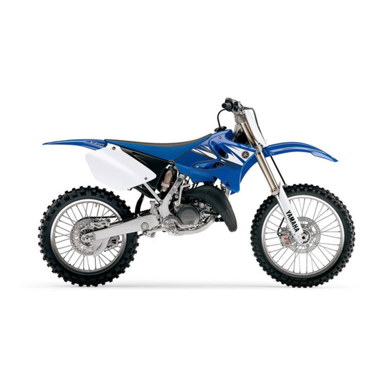
DESCRIPTION GENERAL INFORMATION DESCRIPTION Clutch lever 14. Fuel cock Engine stop switch 15. Air filter Front brake lever 16. Drive chain Throttle grip 17. Shift pedal Radiator cap 18. Starter knob Fuel tank cap 19. Front fork Kickstarter crank Fuel tank Radiator 10. -
Page 12: Identification
There are two significant reasons for knowing the serial number of your machine: 1. When ordering parts, you can give the number to your Yamaha dealer for positive identification of the model you own. VALVE JOINT 2. If your machine is stolen, the au- This valve joint "1"... -
Page 13: Checking Of Connec Tion
CHECKING OF CONNECTION ommended by Yamaha for carefully before reassembly. Al- shown. assembly and adjustment. ways replace piston pin clips after one use. Replace distorted cir- GASKETS, OIL SEALS AND O- clips. When installing a circlip "1", RINGS make sure that the sharp-edged 1. -
Page 14: Special Tools
SPECIAL TOOLS SPECIAL TOOLS The proper special tools are necessary for complete and accurate tune-up and assembly. Using the correct special tool will help prevent damage caused by the use of improper tools or improvised techniques. The shape and part number used for the special tool differ by country, so two types are provided. - Page 15 SPECIAL TOOLS Tool name/Part number How to use Illustration Fuel level gauge "1" This gauge is used to measure the YM-1312-A, 90890-01312 fuel level in the float chamber. Fuel level gauge adaptor "2" YM-01470, 90890-01470 Radiator cap tester These tools are used for checking YU-24460-01, 90890-01325 the cooling system.
-
Page 16: Clutch
Dynamic spark tester This instrument is necessary for YM-34487 checking the ignition system compo- Ignition checker nents. 90890-06754 YAMAHA Bond No. 1215 (ThreeB- This sealant (Bond) is used for ® No. 1215) crankcase mating surface, etc. 90890-85505... -
Page 17: Control Functions
CONTROL FUNCTIONS CONTROL FUNCTIONS ENGINE STOP SWITCH The engine stop switch "1" is located on the left handlebar. Continue push- ing the engine stop switch till the en- gine comes to a stop. THROTTLE GRIP STARTER KNOB (CHOKE) The throttle grip "1" is located on the When cold, the engine requires a right handlebar;... - Page 18 STARTING AND BREAK-IN and avoid engine damage. • When any of the following parts Mixing oil: have been replaced, they must Recommended oil: BREAK-IN PROCEDURES be broken in. Yamalube "2-R" 1. Before starting the engine, fill the CYLINDER AND CRANKSHAFT: (Yamalube racing 2- fuel tank with a break-in oil-fuel About one hour of break-in oper-...
-
Page 19: Torque-Check Points
TORQUE-CHECK POINTS TORQUE-CHECK POINTS Frame construction Frame to rear frame Combined seat and fuel tank Fuel tank to frame Exhaust system Silencer to rear frame Engine mounting Frame to engine Engine bracket to engine Engine bracket to frame Steering Steering stem to handlebar Steering stem to frame Steering stem to upper bracket Upper bracket to handlebar... -
Page 20: Cleaning And Storage
CLEANING AND STORAGE CLEANING AND STORAGE the carburetor float bowl. 2. Remove the spark plug, pour a ta- CLEANING blespoon of SAE 10W-30 motor Frequent cleaning of your machine oil in the spark plug hole, and re- will enhance its appearance, maintain install the plug. -
Page 21: Specifications
GENERAL SPECIFICATIONS SPECIFICATIONS GENERAL SPECIFICATIONS Model name: YZ125X1 (USA, CDN) YZ125 (EUROPE, ZA) YZ125X (AUS, NZ) Model code number: 1C3D (USA, CDN) 1C3E (EUROPE) 1C3G (AUS, NZ, ZA) Dimensions: USA, AUS, NZ, ZA EUROPE, CDN Overall length 2,135 mm (84.1 in) 2,139 mm (84.2 in) ←... -
Page 22: Engine
MAINTENANCE SPECIFICATIONS Transmission type Constant mesh, 6-speed Operation Left foot operation Gear ratio: 31/13 (2.385) 29/15 (1.933) 27/17 (1.588) 23/17 (1.353) 24/20 (1.200) 23/21 (1.095) Chassis: USA, ZA, AUS, NZ EUROPE, CDN ← Frame type Semi double cradle Caster angle 25.5 °... - Page 23 MAINTENANCE SPECIFICATIONS Item Standard Limit Out of round limit ---- 0.01 mm (0.0004 in) Piston: Piston size/ 53.957–53.972 mm (2.1243–2.1249 in) ---- Measuring point "H" 17.5 mm (0.69 in) ---- Piston clearance 0.040–0.045 mmm (0.0016–0.0018 in) 0.1 mm (0.004 Piston offset 0.5 mm (0.019 in)/EX-side ---- Piston pin:...
- Page 24 MAINTENANCE SPECIFICATIONS Item Standard Limit Warp limit ---- 0.2 mm (0.008 Clutch spring free length 40.1 mm (1.579 in) 38.1 mm (1.500 in) Quantity ---- Clutch housing thrust clearance 0.15–0.26 mm (0.006–0.010 in) ---- Clutch housing radial clearance 0.014–0.046 mm (0.0006–0.0018 in) ---- Clutch release method Inner push, cam push...
-
Page 25: Chassis
MAINTENANCE SPECIFICATIONS Item Standard Limit Water pump: Type Single-suction centrifugal pump ---- CHASSIS Item Standard Limit Steering system: Steering bearing type Taper roller bearing ---- Front suspension: USA, CDN, ZA, AUS, EUROPE ← Front fork travel 300 mm (11.8 in) ---- ←... -
Page 26: Electrical
Clutch lever free play (lever end) 8–13 mm (0.31–0.51 in) ---- Throttle grip free play 3–5 mm (0.12–0.20 in) ---- ELECTRICAL Item Standard Limit Ignition system: Ignition timing (B.T.D.C.) 0.48 mm (0.019 in) ---- Advancer type Electrical ---- CDI: Magneto-model (stator)/Manufacturer 1C3-10/YAMAHA ----... -
Page 27: Tightening Torques
20 °C (68 °F) (Black-Green/ ---- Blue) Ω Pickup coil resistance (color) 248–372 at 20 °C (68 °F) (White/Blue- ---- White/Red) CDI unit-model/manufacturer 1C3-10/YAMAHA ---- Ignition coil: Model/manufacturer 1C3-00/YAMAHA ---- Minimum spark gap 6 mm (0.24 in) ---- Ω... - Page 28 Thank you very much for your reading. Please click here and go back to the website. Then, download the complete manual instantly. No waiting.
- Page 29 TIGHTENING TORQUES Tightening torque Part to be tightened Thread size Q'ty m•kg ft•lb Throttle cable adjust bolt and locknut M8 × 1.25 Throttle cable M6 × 0.75 Crankcase M6 × 1.0 Right crankcase cover M6 × 1.0 Left crankcase cover M6 ×...
- Page 30 TIGHTENING TORQUES Tightening torque Part to be tightened Thread size Q'ty m•kg ft•lb Bleed screw (front fork) and base valve M5 × 0.8 △ Front fork and front fork protector M6 × 1.0 △ Cable guide (front brake hose) and lower bracket M6 ×...