Advertisement
Quick Links
Meters and Energy Cost Allocation
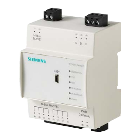
M-bus Level converter 60
WTV531-GA5060
A6V10844290_en--_b
2019-10-21
The level converter WTV531-GA5060 is an interface between M-bus meters and
reader systems. PC software ACT531 reads the data locally or via the Internet
using an optional web server.
●
Connect up to 60 M-bus devices (max. 60 simply M-bus loads)
●
Use up to six level converters on one M-bus network with a max. of 360 simple
M-bus loads
●
Local data read out with the ACT531 PC software via USB or the
RS-232 interface
●
Remote read out via M-bus web server
●
Local data read out via a PXC device via the RS-232 interface
●
Reads a max. 1,000 logical devices on a level converter network
●
Supply voltage AC/DC 24 V
Smart Infrastructure
Advertisement

Related Manuals for Siemens WTV531-GA5060


Summary of Contents for Siemens WTV531-GA5060
- Page 1 Meters and Energy Cost Allocation M-bus Level converter 60 WTV531-GA5060 The level converter WTV531-GA5060 is an interface between M-bus meters and reader systems. PC software ACT531 reads the data locally or via the Internet using an optional web server. ●...
- Page 2 The level converter is the communications interface to read up to 60 M-bus devices (simple M-bus loads). The data is read out: ● Locally with the ACT531 PC software via USB ● Locally with the ACT531 PC software via the RS-232 interface ●...
- Page 3 Functions Operating modes The data can be read in different ways. Local data read out with the ACT531 software via the USB connection The level converter is used as the communication interface between M-bus devices and a laptop using the ACT531 software. The ACT531 software can read a max. of 1,000 logical devices.
- Page 4 Remote read out via M-bus web server The level converter is used as the communication interface between M-bus devices and a M-bus web server. The master level converter WTV531(A) is connected to a M-bus web server WTV676.. via the RS-232 interface (terminals A, B, C). The following slave level converters (B) can be connected via the M-bus slave connection.
- Page 5 Local data read out with Desigo CC via the RS-232 interface The TX Open module integrates M-bus devices via a RS-232 interface to the Desigo CC building management platform. Additional information on the Desigo CC management platform is available in the engineering guide 'Desigo TM TX Open, TX M-bus', document CM110572.
- Page 6 Level converter as individual component The level converter can be used as an individual component on one M-bus network with up to 60 devices. Level converter to extend a M-bus network The level converter extends a M-bus network with up to six level converters connected in parallel.
- Page 7 Indicators The level converter has six LEDs on the front side for indicating the operating state. USB activity The LED indicates the USB interface connection state. ● Flashes 2 x -> The device is ready to connect to a PC using a mini USB-B cable. ●...
- Page 8 Technical design Topology The M-bus permits various network topologies. The devices can be connected to the level converter in a line, bus, star, or tree topology, or a combination thereof. Ring topology is not permitted. Bus cable polarity is not relevant, simplifying installation. Line topology Bus topology Star topology...
- Page 9 Combination of topologies Ring topology Smart Infrastructure A6V10844290_en--_b 2019-10-21...
- Page 10 *Shielded cabling required at a distance in excess of 1,000 m (see EN13757-2 appendix E). Signal specification M-bus Condition Minimum Typical Maximum Measuring unit Number simple WTV531-GA5060 M-bus loads per segment ≤ 382 nF Transfer rate 2400 9600 baud Segment...
-
Page 11: Connection Terminals
Connection terminals The device as the following connection terminals / LEDs. Power supply AC/DC 24 V Terminals (8) and (9) Connections for M-bus meters Connections for following level converters, if this one is used as the master. Terminals (6) and (7) Non-isolated connections to connect to a M- bus web server and / or... - Page 12 Engineering, commissioning, User's guide M-bus web server WTV676-HB6035, A6V11157985 operation, and troubleshooting M-bus level converter WTX631-GA0090 M-bus level converter WTV531-GA5060 RF converter WTX660-E05060 Engineering instructions Desigo TM TX Open, TX M-bus CM110572 Related documents such as environmental declarations, CE declarations, etc., can be downloaded at the following Internet address: http://siemens.com/bt/download...
- Page 13 Comply with all local and currently applicable laws and regulations. Warranty service Technical data on specific applications are valid only together with Siemens products listed under "Equipment combinations". Siemens rejects any and all warranties in the event that third-party products are used.
-
Page 14: Technical Data
Technical data Power supply Operating voltage AC/DC 24 V +/- 10 % AC frequency 50/60 Hz Power consumption 3 W + 0.07 W for each connected M-bus device Maximum power consumption 12 W, 12 VA Internal fuse PTC resistance and varistor Fusing of supply lines Fusible links Max. - Page 15 Environmental compatibility The product environmental declaration A6V10922887 *) contains data on environmentally compatible product design and assessments (RoHS compliance, materials composition, packaging, environmental benefit, disposal). *) Documents can be downloaded at http://siemens.com/bt/download. Degree of protection IP class IP20 per EN60529...
- Page 16 Dimensions H = 62 mm All dimensions in mm Issued by © Siemens Switzerland Ltd, 2016 Siemens Switzerland Ltd Technical specifications and availability subject to change without notice. Smart Infrastructure Global Headquarters Theilerstrasse 1a CH-6300 Zug Tel. +41 58 724 2424 www.siemens.com/buildingtechnologies...