Miele B 890 Technical Information
Hide thumbs
Also See for B 890:
- Operating instructions manual (36 pages) ,
- Reference manual (4 pages) ,
- Product dimensions (1 page)
Table of Contents
Advertisement
Quick Links
Advertisement
Table of Contents

Related Manuals for Miele B 890


Summary of Contents for Miele B 890
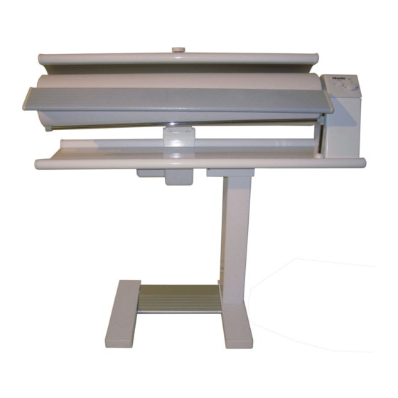
- Page 1 TECHNICAL INFORMATION B 890 and B 990 Rotary Irons (US Models) © 2011 Miele USA...
-
Page 2: Table Of Contents
B 890/B 990 Technical Information Table of Contents Warning and Safety Instructions ............5 General ...................... 5 Touch Current Measurement ..............6 Risk of Injury Due to Tilting Mechanism ............ 6 Modification History ................. 6 Technical Data ..................7 Layout of Electrical Components ............9 Stand ....................... - Page 3 Figure D-1: Layout of Electrical Components ..............9 Figure D-2: Overview of Rotary Iron ................10 Figure D-3: Overview of (a) B 890 and (b) B 990 Controls ..........10 Figure 010-1: Main Electronic N2, B 890 ................ 12 Figure 010-2: Main Electronic N2, B 990 ................ 13 Figure 010-3: Main Electronic Cover ................
- Page 4 B 890/B 990 Technical Information Figure 020-5: Locking the Iron in Place ................24 Figure 020-6: Temperature Regulator Screws ..............26 Figure 020-7: Finger Guard Switch ................. 27 Figure 030-1: Heater Plate ....................29 Figure 030-2: Hinge Pressure Spring Bolt and Cross Pin ..........31 Figure 035-1: Leaf Spring and Holder ................
-
Page 5: Warning And Safety Instructions
B 890/B 990 Technical Information Warning and Safety Instructions General Service and repair work should only be carried out by suitably qualified persons in accordance with all appropriate local and national safety regulations. Servicing, modification, testing and maintenance of electrical appliances should only be carried out in accordance with all appropriate legal requirements, accident prevention regulations and valid standards. -
Page 6: Touch Current Measurement
B 890/B 990 Technical Information Touch Current Measurement Note: Touch current measurement should be carried out on all accessible conductive parts that are not connected to ground. Warning! Touch current measurement should only be carried out after the ground connection of the appliance under test has been checked and found to be... -
Page 7: C Technical Data
B 890/B 990 Technical Information Technical Data Model B 890, B 990 Type Transportable folding unit for domestic use External dimensions, operating Height x width x depth: 37” x 39.4” x 16.4” position External dimensions, storage Height x width x depth: 41.8” x 16.4” x 16.4”... - Page 8 B 890/B 990 Technical Information The appliance is supplied with a power cord and NEMA 5-15 plug, ready for connection to an AC single-phase 120V 60Hz supply. The fuse rating is 20 amps. The actual amperage draw from the appliance is 13 amps.
-
Page 9: Layout Of Electrical Components
B 890/B 990 Technical Information Layout of Electrical Components The layout for the B 890 and B 990 is also included in the wiring diagram. Figure D-1: Layout of Electrical Components A1 Control panel/electronic B2/10 Temperature control, heater plate F6/5 Safety switch, finger guard... -
Page 10: Figure D-2: Overview Of Rotary Iron
B 890/B 990 Technical Information Figure D-2: Overview of Rotary Iron Figure D-3: Overview of (a) B 890 and (b) B 990 Controls... -
Page 11: Stand
B 890/B 990 Technical Information Stand... -
Page 12: Function
Function Main Electronic The B 890 and B 990 are equipped with two (2) separate electronic board assemblies: the control electronic (A1), illustrated in Section 050-2.2, and the main electronic (N2). The main electronic is located beneath a cover on the top of the stand, and is responsible for providing power to components. -
Page 13: Transformer
B 890/B 990 Technical Information Figure 010-2: Main Electronic N2, B 990 Transformer The transformer is mounted to the base plate, and is covered by the stand. The transformer is responsible for reducing voltage from 120VAC to 24VDC for the electronic and several other components. -
Page 14: Fault Repair
B 890/B 990 Technical Information Fault Repair Foot Switch Does Not Operate the Roller Cause: Switch defective. Remedy: Replace the foot switch; see Section 010-4.1. Service Foot Switch (2S26, 2S27) Removal 1. Tilt the ironing table to its horizontal position; see Section 020-4.1. -
Page 15: Figure 010-3: Main Electronic Cover
B 890/B 990 Technical Information Figure 010-3: Main Electronic Cover 7. Remove the T20 screw securing the main electronic to the stand (Figure 010-4, Item 1). Slide the main electronic out of the stand. Figure 010-4: Main Electronic Screw 8. Disconnect all connections from the old electronic and connect them on the new electronic, one at a time. -
Page 16: Transformer Removal
B 890/B 990 Technical Information necessary, and then feed the Bowden cable/spring assembly as far down the stand as possible. Pull the twine or cord through the bottom of the stand and tie or tape it down. 14. Grab the J-hook with pliers and reattach it to the base. -
Page 17: Bowden Cable Replacement
B 890/B 990 Technical Information stand and reconnect them to the main electronic. 5. Re-install the main electronic. Do not re-install the electronic's cover. 6. Tilt the ironing table to its horizontal position; see Section 020-4.1. 7. Lay the iron on its back again. -
Page 18: Figure 010-5: Bowden Cable And Plastic Hinge
B 890/B 990 Technical Information Figure 010-5: Bowden Cable and Plastic Hinge 11. Carefully remove the Bowden cable holder from the table, via the opening behind the hinge. This holder is very small and can fall inside the table! 12. Remove the Bowden cable pin from the table (Figure 010-6, Item 1). -
Page 19: Handle Replacement
B 890/B 990 Technical Information 17. Install the Bowden cable pin and Bowden cable cord in the Bowden cable holder (Figure 010-7, Item 3). 18. Feed the Bowden cable back into the table; insert through the round opening and hold in place. -
Page 20: Figure 010-8: Handle Removal
B 890/B 990 Technical Information 010-8, Item 3). 7. Remove the two T20 screws securing the bottom of the motor bracket. 8. Lift the base of the iron slightly, so that the plate and table are pressed together and the heater plate motor comes out of the table in one piece. -
Page 21: Heater Plate
B 890/B 990 Technical Information Heater Plate... -
Page 22: Function
B 890/B 990 Technical Information Function Heater Circuit The heater plate contains three heater elements within a parallel circuit (1kW/52 per element). (Refer to the wiring diagram.) The temperature is regulated using an adjustable temperature control device (see the operating manual) mounted in series before the heating elements. -
Page 23: Finger Guard Switch
B 890/B 990 Technical Information Finger Guard Switch The finger guard is the small lip in the front of the heater plate assembly that can be lifted slightly. The finger guard switch is actuated if the finger guard is lifted or moved from its regular position. This system ensures that, if the operator should accidentally make contact with the heater plate while the roller is turning, power is interrupted to prevent injuries. -
Page 24: Service
B 890/B 990 Technical Information Remedy: 1. Check the input voltage to the heater plate. 2. Check the output voltage to the heater plate. 3. If there is input voltage but no output voltage, replace the main electronic. See Section 010-4.2. -
Page 25: Insulation Matting Removal
Temperature Regulator Sensor (1B2/10) Replacement 1. Remove the insulation matting; see Section 020-4.3. 2. Lever off the switch knob with a lid opener or yellow Miele tool and remove it with the fascia. 3. Remove the T20 screws from the temperature regulator. See Figure 020- 6, Item 1. -
Page 26: High-Temperature Cutout (2B2/10, 3B2/10) Replacement
B 890/B 990 Technical Information Figure 020-6: Temperature Regulator Screws 5. Disconnect the plug connections and connect them on the new temperature regulator, one at a time. This prevents incorrect connection. 6. Use a screwdriver to bend open the channels holding the temperature regulator sensor on the heater plate. -
Page 27: Finger Guard Switch (F6/5) Removal
B 890/B 990 Technical Information Finger Guard Switch (F6/5) Removal Note: The switching point of the finger guard strip cannot be modified. 1. Open the heater plate cover; see Section 020-4.2. 2. Remove the 2 T10 screws from the switch holder. See Figure 020-7, Item 1. -
Page 28: Heater Plate Motor
B 890/B 990 Technical Information Heater Plate Motor... -
Page 29: Function
B 890/B 990 Technical Information Function Motor Operation The heater plate drives are actuated by the user via the foot plate (refer to Section 010-2.3). The drive motor (Figure 030-1, Item 6) is then energized with 24VDC. The shaft of the drive motor is connected to the eccentric cam (Figure 030-1, Item 7) via an E-clip connection (Figure 030-1, Item 5);... -
Page 30: Service
B 890/B 990 Technical Information Service Microswitch (S26, S27) Removal 1. Tilt the ironing table to its horizontal position; see Section 020-4.1. 2. Remove the cover from the heater plate motor (two T20 screws) (Figure 010-6, Item 2). 3. Disconnect the plug from the appropriate switch. -
Page 31: Figure 030-2: Hinge Pressure Spring Bolt And Cross Pin
B 890/B 990 Technical Information 010-6, Item 2). 4. Unscrew the T30 bolt (Figure 030-2, Item 1) from the cross pin (Figure 030-2, Item 2). 5. Apply Loctite 243 locking compound to the end of the bolt. 6. Screw the bolt in so that the pressure spring is compressed to a length of approximately 1 ⁄... -
Page 32: Lifting Arm
B 890/B 990 Technical Information Lifting Arm... -
Page 33: Fault Repair
B 890/B 990 Technical Information Fault Repair Emergency Release Does Not Allow Laundry to Be Removed Cause: Leaf spring defective. Remedy: Replace the leaf spring with holder; see Section 035-4.1. Heater Plate Cannot Be Lowered Completely Cause: The emergency release springs open while the iron is in use. The faulty component here is the catch. -
Page 34: Figure 035-1: Leaf Spring And Holder
B 890/B 990 Technical Information Figure 035-1: Leaf Spring and Holder... -
Page 35: Roller
B 890/B 990 Technical Information Roller... -
Page 36: Fault Repair
B 890/B 990 Technical Information Fault Repair Laundry Not Taken In Cause: Ironing cloth is too smooth. Remedy: Replace the ironing cloth; see Section 040-4.2. Note: Wash the ironing cloth in a washing machine at 140°F (60°C) to raise the nap and roughen the surface. -
Page 37: Service
B 890/B 990 Technical Information Service Roller Removal 1. Tilt the ironing table to its horizontal position; see Section 020-4.1. Figure 040-1: Feed Board Removal 2. Remove the feed board (Figure 040-1). 3. Remove the hanging rail. 4. Open the ironing cloth at the drawstring end. Complete removal of cloth is not necessary. -
Page 38: Ironing Cloth Replacement
B 890/B 990 Technical Information 8. When replacing the end cap, ensure that its notch aligns with the tab on the interior of the roller. See Figure 040-2, Item A. Ironing Cloth Replacement See the operating instructions. Note: When changing the ironing cloth, the roller must be cold. -
Page 39: Roller Motor
B 890/B 990 Technical Information Roller Motor... -
Page 40: Function
B Roller retaining screw (1) Control Electronic The B 890 and B 990 are equipped with two (2) separate electronic board assemblies: the main electronic (N2), illustrated in Section 010-2.1, and the control electronic (A1). The control electronic is attached to the inside of the... -
Page 41: Fault Repair
1. Tilt the ironing table to its horizontal position; see Section 020-4.1. 2. Lever off the switch knob using a lid opener or yellow Miele tool. 3. Remove the T20 screw from the rear of the control electronic cover. -
Page 42: Drive Shaft Removal
B 890/B 990 Technical Information Note: The plug contacts are sometimes not coded. Take care when replacing the control electronic to connect the plugs one by one exactly as they were before. This prevents incorrect connection. 7. Remove the three T20 screws securing the control electronic to the cover. -
Page 43: Figure 050-2: Screws Securing Roller Drive Motor To Frame
B 890/B 990 Technical Information Figure 050-2: Screws Securing Roller Drive Motor to Frame 10. Remove the motor partially by lifting it upward. 11. Disconnect the wiring harness from the motor. 12. Lift the motor completely out of the frame.