Table of Contents
Advertisement
Quick Links
Download this manual
See also:
System Description
Advertisement
Table of Contents

Related Manuals for Pilz PSSuniversal


Summary of Contents for Pilz PSSuniversal
- Page 1 Technical Catalogue PSSuniversal Planning Guide Issue 01/05...
-
Page 2: Table Of Contents
PSSuniversal Contents Page PSSuniversal system Basics System description Modular structure 1.1-1 Module bus 1.1-2 Structure of module bus 1.1-2 Maximum system expansion 1.1-3 System limits 1.1-3 Local enable principle 1.1-4 Connection labelling on the base modules 1.1-5 Colour marking of connection levels 1.1-5... - Page 3 PSSuniversal Modules Head modules PSSu H SB 2.1-1 PSSu H SB DP 2.1-9 Supply voltage modules PSSu E F PS 2.2-1 PSSu E F PS1 2.2-11 PSSu E F PS-P 2.2-21 PSSu E F BSW 2.2-31 Digital input/output (standard) PSSu E S 4DI 2.3-1...
-
Page 4: System Description
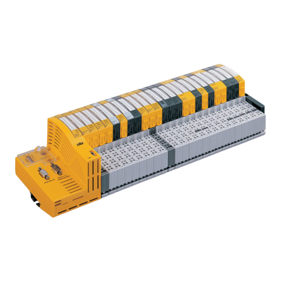
Modular structure Head module Input/output modules Connects the sensor/actuator Available for a wide range of The PSS universal (PSSu) from Pilz is level for standard applications to input/output functions a modular system for use in the master controllers via various... -
Page 5: Module Bus
PSSuniversal Basics System description Module bus to form supply groups. In this case it is necessary to use an The module bus is formed by appropriate supply module, which arranging the base modules together disconnects the supply (module and connecting them via a supply, periphery supply and C- mechanical latch. -
Page 6: Maximum System Expansion
PSSuniversal Basics System description Maximum system expansion Module type Number of modules per system Explanation Input/output modules in total Max. 64 Details are valid for designing a PSSu (identifier: PSSu E F ... / PSSu E S ...) system with any combination of ST modules and FS modules, provided all the following conditions are met. -
Page 7: Local Enable Principle
PSSuniversal Basics System description Local enable principle Operation of the local enable principle The new local enable principle The configured FS outputs are technique means that outputs on driven via a standard bus system. failsafe output modules can now be... -
Page 8: Connection Labelling On The Base Modules
PSSuniversal Basics System description Connection labelling on the base Colour marking of connection levels Connection levels 2 and 3 modules On I/O modules, connection levels The colour marking on the different 2 and 3 typically contain the The connections on the base... -
Page 9: Separating Supplies To Form Supply Groups
PSSuniversal Basics System description Separating supplies to form supply In each case you should take note of groups the description of the relevant electronic supply voltage module. Supply groups are formed by separating the 24 V supply (periphery For example, supplies can be... -
Page 10: Installation
PSSuniversal Basics Installation Mounting position Module layout To form supply groups, an additional voltage supply module A PSSu system should preferably The first module on a PSSu is required at the start of each be installed horizontally on a system is always a head module. -
Page 11: Mounting Distances
PSSuniversal Basics Installation Mounting distances Appropriate air conditioning may also be required. The values stated for The values stated in the diagram ambient temperature must be below are minimum specifications. maintained. These values can be found in the technical details for the individual modules. -
Page 12: Installing The Head Module
PSSuniversal Basics Installation Installing the head module Procedure: - Slot the groove on the head Prerequisites: module on to the mounting rail - The mounting rail must already from below [1]. be installed. - Push the head module back [2]... -
Page 13: Removing The Head Module
PSSuniversal Basics Installation Removing the head module Procedure: - Using a screwdriver, push the Prerequisite: rear locking element [1] - The supply voltage must be upwards until the locking hook switched off releases the anchor. - The bus connections must be... -
Page 14: Installing Base Modules
PSSuniversal Basics Installation Installing base modules with screw terminals and base - Push the base module back [2] modules with cage clamp until you hear it lock into Prerequisite: The head module terminals. position. must already be installed. - All contacts should be... -
Page 15: Removing Base Modules
PSSuniversal Basics Installation Removing base modules Procedure: - On the mounting rail, slide the The same procedure applies for all base module to the right [3] Prerequisite: base modules (e.g. base modules - Using a screwdriver, push the - The supply voltage on the in grid widths 1 x 12.6 mm,... -
Page 16: Installing An End Bracket At The Start Of The System
PSSuniversal Basics Installation Installing an end bracket at the start Procedure: - Place the end bracket on the of the system - Use a screwdriver for slotted- mounting rail, to the left of the head screws (M2). head module [1]. -
Page 17: Installing A Terminating Plate And End Bracket At The End Of The System
PSSuniversal Basics Installation Installing a terminating plate and end bracket to be positioned on the If an additional end bracket (metal bracket at the end of the system mounting rail. version) is required to secure the - Place the end bracket on the... -
Page 18: Removing A Terminating Plate And End Bracket At The End Of The System
PSSuniversal Basics Installation Removing a terminating plate and - Loosen the fixing screw on the end bracket at the end of the system end bracket until the terminals’ clamping force is lifted. Procedure: - Remove the terminating plate - Use a screwdriver for slotted- and integrated end bracket head screws (M2). -
Page 19: Inserting An Electronic Module
PSSuniversal Basics Installation Inserting an electronic module Electronic modules with outputs Procedure: (output modules) may only be - The electronic module must NOTICE inserted or removed when the audibly lock into position [1]. Modules may be inserted and load is switched off. -
Page 20: Mechanical Coding
PSSuniversal Basics Installation Mechanical coding Overview of the mechanical coding Electronic modules have a two-part elements on electronic modules coding element. The first time an electronic module is plugged into a base module, one part of the coding Electronic module... -
Page 21: Removing An Electronic Module
PSSuniversal Basics Installation Removing an electronic module Electronic modules with outputs Procedure: (output modules) may only be Press the locking mechanisms [1] NOTICE inserted or removed when the together and at the same time Ensure that a correct contact is load is switched off. -
Page 22: Earthing
PSSuniversal Basics Installation Earthing When modules are attached to the mounting rail, contact with the mounting rail is made via a contact spring. The mounting rail should be earthed appropriately. A special earthing terminal that can be attached to the mounting rail is available as an accessory. - Page 23 PSSuniversal Basics Installation Notes Status 01/05 1.2-14...
-
Page 24: Head Modules Pssu H Sb
PSSuniversal Head modules PSSu H SB Module features Safety features SafetyBUS p interface for The module meets the following switching failsafe inputs/outputs safety requirements: via SafetyBUS p Watchdog for life monitoring USB port for PC connection Protection against over- - Commissioning and service... - Page 25 LED “USB” interface. - SafetyBUS p interface: male 9- pin D-SUB connector “SafetyBUS p” - Ability to connect the Pilz FO coupler PSS SB SUB-D F0. - Device address: can be set via the two rotary switches “SB ADDRESS”. Valid device addresses: ...
- Page 26 SafetyBUS p error reaction: SafetyBUS p If an error occurs, all the outputs The module has various LEDs to in the affected I/O-Group are shut The system is configured using Pilz display down safely and the I/O-Group configuration software. - System status switches to a STOP condition.
- Page 27 Assignment Male 9-pin D-SUB connector n.c. CAN_L (brown) CAN_GND (white) n.c. CAN_SHLD n.c. CAN_H (green) Supply voltage for Pilz FO coupler n.c. n.c. = not connected Assignment Mini-B USB connector VBUS +5 VDC USB Data- USB Data+ n.c. Ground n.c. = not connected Status 01/05 2.1-4...
- Page 28 PSSuniversal Head modules PSSu H SB Installation Install the appropriate end bracket on the mounting rail to the left of Horizontal installation is the head module [2]. preferable! Always attach an appropriate Vertical installation is possible, but supply voltage module to the...
- Page 29 PSSuniversal Head modules PSSu H SB Dimensions 21,6 mm 50,2 mm 72,6 mm Using this data sheet This data sheet is only intended for use during configuration. NOTICE Please refer to the operating manual during commissioning and operation. Status 01/05...
- Page 30 PSSuniversal Head modules PSSu H SB Technical details PSSu H SB Function Modular I/O system for decentralised applications Application range Failsafe applications conforming to EN 954-1, 03/97, DIN V 19 250, 05/94, DIN VDE 0116, 09/97, EN IEC 61508, 12/98...
- Page 31 PSSuniversal Head modules PSSu H SB Order reference Description Order no. PSSu H SB 312 010 (Head module with SafetyBUS p interface) Order reference for accessories Description Order no. Operating manual in German In progress Operating manual in English In progress...
-
Page 32: Pssu H Sb Dp
PSSuniversal Head modules PSSu H SB DP Module features Module description SafetyBUS p interface for The module meets the requirements switching failsafe inputs/outputs of EN IEC 61508 and EN 954-1 via SafetyBUS p Category 4. The module may be PROFIBUS interface for switching... - Page 33 9-pin D-SUB connector coupler for PROFIBUS-DP. “SafetyBUS p” - Station address can be set via - Ability to connect the Pilz FO the binary coded DIP switch coupler PSS SB SUB-D F0. “ADDRESS” - Device address: can be set via Valid station addresses: the two rotary switches “SB...
- Page 34 SafetyBUS p error reaction: SafetyBUS p If an error occurs, all the outputs The module has various LEDs to in the affected I/O-Group are shut The system is configured using Pilz display down safely and the I/O-Group configuration software. - System status switches to a STOP condition.
- Page 35 PSSuniversal Head modules PSSu H SB DP Head module LED status “BF” LED status “Run” No supply voltage or OFF ON PROFIBUS interface start-up is not yet x 10 complete 312 025 SB ADDRESS Lights red Bus error on PROFIBUS...
- Page 36 Male 9-pin D-SUB connector n.c. CAN_L (brown) CAN_GND (white) n.c. CAN_SHLD n.c. CAN_H (green) Supply voltage for Pilz FO coupler n.c. n.c. = not connected PROFIBUS-DP Assignment Female 9-pin D-SUB connector n.c. conforms to the guidelines of the n.c. PROFIBUS User Group (PNO).
- Page 37 PSSuniversal Head modules PSSu H SB DP Installation Install the appropriate end bracket on the mounting rail to the left of Horizontal installation is the head module [2]. preferable! Always attach an appropriate Vertical installation is possible, but supply voltage module to the...
- Page 38 PSSuniversal Head modules PSSu H SB DP Dimensions 21,6 mm 75,2 mm 72,6 mm Using this data sheet This data sheet is only intended for use during configuration. NOTICE Please refer to the operating manual during commissioning and operation. Status 01/05...
- Page 39 PSSuniversal Head modules PSSu H SB DP Technical details PSSu H SB Function Modular I/O system for decentralised applications Application range Failsafe applications conforming to EN 954-1, 03/97, DIN V 19 250, 05/94, DIN VDE 0116, 09/97, EN IEC 61508, 12/98...
- Page 40 PSSuniversal Head modules PSSu H SB DP Order reference Description Order no. PSSu H SB DP 312 025 (Head module with SafetyBUS p interface and PROFIBUS-DP interface) Order reference for accessories Description Order no. Operating manual in German In progress...
- Page 41 PSSuniversal Head modules PSSu H SB DP Notes Status 01/05 2.1-18...
-
Page 42: Supply Voltage Modules
PSSuniversal Supply voltage PSSu E F PS Module features Supply module to refresh the module supply and periphery Housing width: 12.6 mm supply (1 x grid width) Supply module to form supply Supply for max. 12 modules groups Separate 24 VDC infeed for... - Page 43 PSSuniversal Supply voltage PSSu E F PS Function description - Module supply (5 VDC) for If galvanic isolation is required subsequent modules (right- between the module supply and Using the module as the first hand side) periphery supply, this is achieved...
- Page 44 PSSuniversal Supply voltage PSSu E F PS Module diagnostics Supply voltage Connect together the 0 V The module has various LEDs to The supply voltages for module connections on all the 24 V power display supply and periphery supply may supplies and earth the 0 V supply - Module supply status (“5 V”)
- Page 45 PSSuniversal Supply voltage PSSu E F PS Base modules - To provide the head module and subsequent (right-hand) Terminal configuration modules with the module - General supply module supply, periphery supply and C-rail supply. Base module Terminal configuration Screw terminals:...
- Page 46 PSSuniversal Supply voltage PSSu E F PS - Supply module to refresh the - To interrupt the incoming (left- - To provide subsequent (right- hand) module supply, periphery module supply and periphery hand) modules with the module supply supply, C-rail...
- Page 47 PSSuniversal Supply voltage PSSu E F PS Connection Supply type Connection General supply with base module - PSSu BS 1/8S or - PSSu BS 1/8C Note: When the electronic module PSSu E F PS is used with the listed base...
- Page 48 PSSuniversal Supply voltage PSSu E F PS Installation the right of the head module - Slide the base module to the and click into position on the left until you hear it click into Horizontal installation is rail. the last base module to be...
- Page 49 PSSuniversal Supply voltage PSSu E F PS Inserting an electronic module Electronic modules should INFORMATION preferably be inserted on to base The first time an electronic module is NOTICE modules that are already installed inserted on to a base module, the Ensure that a correct contact is and wired.
- Page 50 PSSuniversal Supply voltage PSSu E F PS Technical details PSSu E F PS Function Supply voltage for decentralised applications of the PSSu series Application range Failsafe applications conforming to EN 954-1, 03/97, DIN V 19 250, 05/94, DIN VDE 0116, 09/97,...
- Page 51 PSSuniversal Supply voltage PSSu E F PS Order reference Description Order no. PSSu E F PS 312 190 (Electronic module) PSSu BS 1/8S 312 650 (Base module with screw terminals, to be used only as the first module after the head module)
-
Page 52: Pssu E F Ps1
PSSuniversal Supply voltage PSSu E F PS1 Module features Supply module to refresh the module supply and periphery Housing width: 25.2 mm supply (2 x grid width) Supply module to form supply Supply for max. 20 modules groups Separate 24 VDC infeed for... - Page 53 PSSuniversal Supply voltage PSSu E F PS1 Function description provided on the module bus for - C-rail supply for subsequent subsequent (right-hand) modules: modules (right-hand side) Using the module as the first - Module supply (+5 VDC) for Each supply group requires its...
- Page 54 PSSuniversal Supply voltage PSSu E F PS1 Module diagnostics Supply voltage Wiring The module has various LEDs to The supply voltages for module Connect together the 0 V display the status of the supply and periphery supply may connections on all the 24 V power - Module supply (5 V) be in the range of +18 VDC ...
- Page 55 PSSuniversal Supply voltage PSSu E F PS1 Base modules modules with the module supply, periphery supply and Terminal configuration C-rail supply - General supply module To provide the head module and subsequent (right-hand) Base module Terminal configuration Screw terminals: + 24 V Module supply...
- Page 56 PSSuniversal Supply voltage PSSu E F PS1 - Supply module - To interrupt the incoming - To provide subsequent (left-hand) module supply, - To refresh the module supply (right-hand) modules with and periphery supply periphery supply, C-rail the module supply, periphery...
- Page 57 PSSuniversal Supply voltage PSSu E F PS1 Connection Supply type Connection General supply with base module - PSSu BS 2/8S or - PSSu BS 2/8C Note: When the electronic module PSSu E F PS1 is used with the listed base modules it may only be used as the...
- Page 58 PSSuniversal Supply voltage PSSu E F PS1 Installation the right of the head module - Slide the base module to the and click into position on the left until you hear it click into Horizontal installation is rail. the last base module to be...
- Page 59 PSSuniversal Supply voltage PSSu E F PS1 Inserting an electronic module Electronic modules should INFORMATION preferably be inserted on to base The first time an electronic module is NOTICE modules that are already installed inserted on to a base module, the Ensure that a correct contact is and wired.
- Page 60 PSSuniversal Supply voltage PSSu E F PS1 Technical details PSSu E F PS1 Function Supply voltage for decentralised applications of the PSSu series Application range Failsafe applications conforming to EN 954-1, 03/97, DIN V 19 250, 05/94, DIN VDE 0116, 09/97,...
- Page 61 PSSuniversal Supply voltage PSSu E F PS1 Order reference Description Order no. PSSu E F PS1 312 191 (Electronic module) PSSu BS 2/8S 312 656 (Base module with screw terminals, to be used only as the first module after the head module)
-
Page 62: Pssu E F Ps-Ppssu
PSSuniversal Supply voltage PSSu E F PS-P Module features Safety features Housing width: 12.6 mm The module meets the following (1 x grid width) safety requirements: Provides the module with the Protection against over- module supply (5 VDC) via the... - Page 63 PSSuniversal Supply voltage PSSu E F PS-P Function description If galvanic isolation is required between the module supply and Module supply (5 VDC) periphery supply, this is achieved The electronics are supplied via by feeding the voltages separately the module bus.
- Page 64 PSSuniversal Supply voltage PSSu E F PS-P Module diagnostics Supply voltage On the module bus, the load current of max. 10 A must not be The module has various LEDs to The supply voltage for periphery exceeded for the periphery...
- Page 65 PSSuniversal Supply voltage PSSu E F PS-P Base modules - To interrupt the incoming (left- - To provide the subsequent hand) periphery supply and C- (right-hand) modules with the Terminal configuration rail periphery supply and C-rail Supply module supply - To refresh the periphery supply...
- Page 66 PSSuniversal Supply voltage PSSu E F PS-P Connection Supply type Connection Supply to refresh the - Periphery supply - C-rail supply with base module - PSSu BS 1/8S or - PSSu BS 1/8C Supply to form supply groups with base module...
- Page 67 PSSuniversal Supply voltage PSSu E F PS-P Installation rail to the right of the head module Secure the final module on the [1] and click into position on the mounting rail with the appropriate Horizontal installation is rail [2]. fixing bracket [4].
- Page 68 PSSuniversal Supply voltage PSSu E F PS-P Inserting an electronic module Electronic modules should INFORMATION preferably be inserted on to base The first time an electronic module is NOTICE modules that are already installed inserted on to a base module, the Ensure that a correct contact is and wired.
- Page 69 PSSuniversal Supply voltage PSSu E F PS-P Technical details PSSu E F PS-P Function Supply voltage for decentralised applications of the PSSu series Application range Failsafe applications conforming to EN 954-1, 03/97, DIN V 19 250, 05/94, DIN VDE 0116, 09/97,...
- Page 70 PSSuniversal Supply voltage PSSu E F PS-P Order reference Description Order no. PSSu E F PS-P 312 185 (Electronic module) PSSu BS 1/8S 312 650 (Base module with screw terminals) PSSu BS 1/8C 312 651 (Base module with cage clamp terminals)
- Page 71 PSSuniversal Supply voltage PSSu E F PS-P Notes Status 01/05 2.2-30...
-
Page 72: Pssu E F Bsw
PSSuniversal Supply voltage PSSu E F BSW Module features Safety features Housing width: 25.2 mm The module meets the following (2 x grid width) safety requirements: 24 VDC infeed for periphery 2 N/O relay contacts connected in supply (24 VDC) - Page 73 PSSuniversal Supply voltage PSSu E F BSW Function description Each output block requires its own block switching module. Module supply (5 VDC) The relationship between the The electronics are supplied via switchable load current and the the module bus. operating temperature is...
- Page 74 1.5 (AWG16) ... 2.5 (AWG12) System configuration The external periphery supply Use copper wiring. must be able to provide a load The system is configured using Pilz current of max. 10 A. On the NOTICE configuration software. module bus, the load current of To prevent contact welding, a fuse max.
- Page 75 PSSuniversal Supply voltage PSSu E F BSW Base modules supply to input/output blocks - To provide subsequent (right- (block switching) hand) modules with the Terminal configuration - To interrupt the incoming (left- periphery supply and C-rail Supply module hand) periphery supply and C-...
- Page 76 PSSuniversal Supply voltage PSSu E F BSW Connection Supply type Connection Supply to input/output blocks (block switching) with base module - PSSu BS 2/8S or - PSSu BS 2/8C Status 01/05 2.2-35...
- Page 77 PSSuniversal Supply voltage PSSu E F BSW Installation Attach the base module to the DIN If necessary: rail to the right of the supply - Label the connection levels Horizontal installation is voltage module [1] and click into with coloured markers. To do preferable! position on the rail [2].
- Page 78 PSSuniversal Supply voltage PSSu E F BSW Inserting an electronic module Electronic modules should INFORMATION preferably be inserted on to base The first time an electronic module is NOTICE modules that are already installed inserted on to a base module, the Ensure that a correct contact is and wired.
- Page 79 PSSuniversal Supply voltage PSSu E F BSW Technical details PSSu E F BSW Function Block switching of the periphery supply for decentralised standard applications of the PSSu series Application range Failsafe applications conforming to EN 954-1, 03/97, DIN V 19 250, 05/94,...
- Page 80 PSSuniversal Supply voltage PSSu E F BSW Order reference Description Order no. PSSu E F BSW 312 230 (Electronic module) PSSu BS 2/8S 312 656 (Base module with C-rail with screw terminals) PSSu BS 2/8C 312 657 (Base module with C-rail with cage clamp terminals) Order reference for accessories Order no.
- Page 81 PSSuniversal Supply voltage PSSu E F BSW Notes Status 01/05 2.2-40...
-
Page 82: Digital Input/Output (Standard) Pssu E S 4Di
PSSuniversal Digital input/output PSSu E S 4DI Module features Properties Housing width: 12.6 mm When the module supply is (1 x grid width) interrupted, the electronics are 4 digital inputs buffered for 20 ms, provided the 2 outputs, with constant voltage of... - Page 83 PSSuniversal Digital input/output PSSu E S 4DI Function description Signal detection at the inputs Module supply (5 VDC) To guarantee that a signal at an input The electronics are supplied via (“0” signal or “1” signal) is detected, the module bus.
- Page 84 Digital input/output PSSu E S 4DI Module diagnostics System configuration Wiring The module has various LEDs to The system is configured using Pilz Signals may be connected using display configuration software and via the unscreened cables. - Module errors (Err) Current limitation is required (e.g.
- Page 85 PSSuniversal Digital input/output PSSu E S 4DI Base modules Terminal configuration Base module Terminal configuration Screw terminals: Without C-rail: PSSu BP 1/8S Input 1 Input 2 Cage clamp terminals: 12-22: 24 V + 24 V output PSSu BP 1/8C (Periphery supply...
- Page 86 PSSuniversal Digital input/output PSSu E S 4DI Installation Attach the base module to the DIN If necessary: rail to the right of the supply - Label the connection levels Horizontal installation is voltage module [1] and click into with coloured markers. To do preferable! position on the rail [2].
- Page 87 PSSuniversal Digital input/output PSSu E S 4DI Inserting an electronic module Electronic modules should INFORMATION preferably be inserted on to base The first time an electronic module is NOTICE modules that are already installed inserted on to a base module, the Ensure that a correct contact is and wired.
- Page 88 PSSuniversal Digital input/output PSSu E S 4DI Technical details PSSu E S 4DI Function Compact programmable safety system for decentralised applications Application range Standard applications Electrical data Supply voltage From module supply: 5 VDC From module supply: ≤ 25 mA...
- Page 89 PSSuniversal Digital input/output PSSu E S 4DI Order reference Description Order no. PSSu E S 4DI 312 400 (Electronic module) PSSu BP 1/8S 312 600 (Base module without C-rail with screw terminals) PSSu BP 1/8C 312 601 (Base module without C-rail with cage clamp terminals) Order reference for accessories Order no.
-
Page 90: Pssu E S 4Do 0.5
PSSuniversal Digital input/output PSSu E S 4DO 0.5 Module features Properties Housing width: 12.6 mm When the module supply is (1 x grid width) interrupted, the electronics are 4 single-pole digital outputs buffered for 20 ms, provided the - Positive-switching... - Page 91 PSSuniversal Digital input/output PSSu E S 4DO 0.5 Function description Module supply (5 VDC) The electronics are supplied via the module bus. Periphery supply (24 VDC) The supply to the outputs is galvanically isolated from the module supply. “0” signal (0 V) at the output:...
- Page 92 Digital input/output PSSu E S 4DO 0.5 Module diagnostics System configuration Wiring The module has various LEDs to The system is configured using Pilz Actuators may be connected display configuration software and via the using unscreened cables. - Module errors (Err) When switching inductive loads, standard bus system.
- Page 93 PSSuniversal Digital input/output PSSu E S 4DO 0.5 Base modules Terminal configuration Base module Terminal configuration Screw terminals: Without C-rail: PSSu BP 1/8S Output 1, single-pole Output 2, single-pole Cage clamp terminals: 12-22: 0 V Periphery supply PSSu BP 1/8C...
- Page 94 PSSuniversal Digital input/output PSSu E S 4DO 0.5 Installation Attach the base module to the DIN If necessary: rail to the right of the supply - Label the connection levels Horizontal installation is voltage module [1] and click into with coloured markers. To do preferable! position on the rail [2].
- Page 95 PSSuniversal Digital input/output PSSu E S 4DO 0.5 Inserting an electronic module Electronic modules should INFORMATION preferably be inserted on to base The first time an electronic module is NOTICE modules that are already installed inserted on to a base module, the Ensure that a correct contact is and wired.
- Page 96 PSSuniversal Digital input/output PSSu E S 4DO 0.5 Technical details PSSu E F 4DO 0.5 Function Compact programmable safety system for decentralised applications Application range Standard applications Electrical data Supply voltage From module supply: 5 VDC From module supply: ≤ 60 mA Current consumption Outputs –...
- Page 97 PSSuniversal Digital input/output PSSu E S 4DO 0.5 Order reference Description Order no. PSSu E S 4DO 0.5 312 405 (Electronic module) PSSu BP 1/8S 312 600 (Base module without C-rail with screw terminals) PSSu BP 1/8C 312 601 (Base module without C-rail with cage clamp terminals)
-
Page 98: Pssu E S 2Do 2
PSSuniversal Digital input/output PSSu E S 2DO 2 Module features Properties Housing width: 12.6 mm When the module supply is (1 x grid width) interrupted, the electronics are 2 single-pole digital outputs buffered for 20 ms, provided the - Positive-switching... - Page 99 PSSuniversal Digital input/output PSSu E S 2DO 2 Function description Module supply (5 VDC) The electronics are supplied via the module bus. Periphery supply (24 VDC) The supply to the outputs is galvanically isolated from the module supply. “0” signal (0 V) at the output:...
- Page 100 Digital input/output PSSu E S 2DO 2 Module diagnostics System configuration Wiring The module has various LEDs to The system is configured using Pilz Actuators may be connected display configuration software and via the using unscreened cables. - Module errors (Err/FS1) When switching inductive loads, standard bus system.
- Page 101 PSSuniversal Digital input/output PSSu E S 2DO 2 Base modules Terminal configuration Base module Terminal configuration Screw terminals: Without C-rail: PSSu BP 1/8S Output 1, single-pole Output 2, single-pole Cage clamp terminals: 12-22: 0 V Periphery supply PSSu BP 1/8C...
- Page 102 PSSuniversal Digital input/output PSSu E S 2DO 2 Installation Attach the base module to the DIN If necessary: rail to the right of the supply - Label the connection levels Horizontal installation is voltage module [1] and click into with coloured markers. To do preferable! position on the rail [2].
- Page 103 PSSuniversal Digital input/output PSSu E S 2DO 2 Inserting an electronic module Electronic modules should INFORMATION preferably be inserted on to base The first time an electronic module is NOTICE modules that are already installed inserted on to a base module, the Ensure that a correct contact is and wired.
- Page 104 PSSuniversal Digital input/output PSSu E S 2DO 2 Technical details PSSu E F 2DO 2 Function Compact programmable safety system for decentralised applications Application range Standard applications Electrical data Supply voltage From module supply: 5 VDC From module supply: ≤ 50 mA Current consumption Outputs –...
- Page 105 PSSuniversal Digital input/output PSSu E S 2DO 2 Order reference Description Order no. PSSu E S 2DO 2 312 410 (Electronic module) PSSu BP 1/8S 312 600 (Base module without C-rail with screw terminals) PSSu BP 1/8C 312 601 (Base module without C-rail with cage clamp terminals)
-
Page 106: Digital Input/Output (Failsafe) Pssu E F 4Di
PSSuniversal Digital input/output PSSu E F 4DI Module features Safety features Housing width: 12.6 mm The module meets the following (1 x grid width) safety requirements: 4 digital inputs When the module supply is 2 outputs, with the option to... - Page 107 PSSuniversal Digital input/output PSSu E F 4DI Function description - Test pulses can switched on/ Signal change behaviour off. Test pulses are switched Module supply (5 VDC) off in the default setting. A If a signal at an input changes, the...
- Page 108 SafetyBUS p to exclude short circuits in the The module has various LEDs to external wiring between different display The system is configured using Pilz inputs and to the “Supply” or - Module errors (Err) configuration software. “Periphery supply”. - Input status...
- Page 109 PSSuniversal Digital input/output PSSu E F 4DI Base modules Terminal configuration Base module Terminal configuration Screw terminals: Without C-rail: PSSu BP 1/8S Input 1 Input 2 Cage clamp terminals: 12-22: T0 Test pulse output 1 or PSSu BP 1/8C + 24 V output...
- Page 110 PSSuniversal Digital input/output PSSu E F 4DI Input circuit Single-channel failsafe input device Dual-channel failsafe input device PSSu BP 1/8S PSSu BP 1/8S PSSu BP 1/8C PSSu BP 1/8C Without test pulses (unchecked) Input device with homogenous channels Without test pulses (unchecked)
- Page 111 PSSuniversal Digital input/output PSSu E F 4DI Input circuit Single-channel failsafe input device Dual-channel failsafe input device PSSu BP 1/8S PSSu BP 1/8S PSSu BP 1/8C PSSu BP 1/8C With test pulses (checked) Input device with homogenous channels With test pulses (checked)
- Page 112 PSSuniversal Digital input/output PSSu E F 4DI Installation Attach the base module to the DIN If necessary: rail to the right of the supply - Label the connection levels Horizontal installation is voltage module [1] and click into with coloured markers. To do preferable! position on the rail [2].
- Page 113 PSSuniversal Digital input/output PSSu E F 4DI Inserting an electronic module Electronic modules should INFORMATION preferably be inserted on to base The first time an electronic module is NOTICE modules that are already installed inserted on to a base module, the Ensure that a correct contact is and wired.
- Page 114 PSSuniversal Digital input/output PSSu E F 4DI Technical details PSSu E F 4DI Function Compact programmable safety system for decentralised applications Application range Failsafe applications conforming to EN 954-1, 03/97, DIN V 19 250, 05/94, DIN VDE 0116, 09/97, EN IEC 61508, 12/98...
- Page 115 PSSuniversal Digital input/output PSSu E F 4DI Environmental data Protection type (EN 60529, 02/00) IP20 Ambient temperature 0 ... +60 °C (EN 60068-2-14, 11/99) Storage temperature (EN 60068-2-1/-2, 07/94) -25 ... +70 °C Climatic suitability 93 % r.h. at 40 °C...
-
Page 116: Pssu E F 4Do 0.5
PSSuniversal Digital input/output PSSu E F 4DO 0.5 Module features Safety features Housing width: 12.6 mm The module meets the following (1 x grid width) safety requirements: 4 single-pole digital outputs Common second shutdown route - Positive-switching - Outputs have a diverse... - Page 117 PSSuniversal Digital input/output PSSu E F 4DO 0.5 Function description Output test Testing an output when the output test is switched off: Module supply (5 VDC) Perform the output test for outputs - The correct switch status is The electronics are supplied via...
- Page 118 SafetyBUS p device such as a main integral suppression), errors may contactor occur, particularly with RC The system is configured using Pilz Appropriate wiring should be used elements, depending on their configuration software. to exclude short circuits in the capacitive share. The SafetyBUS p...
- Page 119 PSSuniversal Digital input/output PSSu E F 4DO 0.5 Base modules Terminal configuration Base module Terminal configuration Screw terminals: Without C-rail: PSSu BP 1/8S Output 1, single-pole Output 2, single-pole Cage clamp terminals: 12-22: 0 V Periphery supply PSSu BP 1/8C...
- Page 120 PSSuniversal Digital input/output PSSu E F 4DO 0.5 Connection Output circuit Without C-rail With C-rail PSSu BP 1/8S PSSu BP-C 1/8S PSSu BP 1/8C PSSu BP-C 1/8C Resistive load/capacitive load Single-channel actuator Resistive load/capacitive load Dual-channel actuator Status 01/05 2.4-15...
- Page 121 PSSuniversal Digital input/output PSSu E F 4DO 0.5 Output circuit Without C-rail With C-rail PSSu BP 1/8S PSSu BP-C 1/8S PSSu BP 1/8C PSSu BP-C 1/8C Capacitive load Feedback loop (FL) To form a feedback loop you will need an input module with test...
- Page 122 PSSuniversal Digital input/output PSSu E F 4DO 0.5 Installation Attach the base module to the DIN If necessary: rail to the right of the supply - Label the connection levels Horizontal installation is voltage module [1] and click into with coloured markers. To do preferable! position on the rail [2].
- Page 123 PSSuniversal Digital input/output PSSu E F 4DO 0.5 Inserting an electronic module Electronic modules should INFORMATION preferably be inserted on to base The first time an electronic module is NOTICE modules that are already installed inserted on to a base module, the Ensure that a correct contact is and wired.
- Page 124 PSSuniversal Digital input/output PSSu E F 4DO 0.5 Technical details PSSu E F 4DO 0.5 Function Compact programmable safety system for decentralised applications Application range Failsafe applications conforming to EN 954-1, 03/97, DIN V 19 250, 05/94, DIN VDE 0116, 09/97,...
- Page 125 PSSuniversal Digital input/output PSSu E F 4DO 0.5 Environmental data Protection type (EN 60529, 02/00) IP20 Ambient temperature 0 ... +60 °C (EN 60068-2-14, 11/99) Storage temperature (EN 60068-2-1/-2, 07/94) -25 ... +70 °C Climatic suitability 93 % r.h. at 40 °C...
-
Page 126: Pssu E F 2Do 2
PSSuniversal Digital input/output PSSu E F 2DO 2 Module features Safety features Housing width: 12.6 mm The module meets the following (1 x grid width) safety requirements: 2 single-pole digital outputs Common second shutdown route - Positive-switching - Outputs have a diverse... - Page 127 PSSuniversal Digital input/output PSSu E F 2DO 2 Function description Output test Testing an output when the output test is switched off: Module supply (5 VDC) Perform the output test for outputs - The correct switch status is The electronics are supplied via (standard configuration, see PSS checked.
- Page 128 System configuration for SafetyBUS p for the 24 VDC avoided (e.g. on contactors with - Use dual actuators integral suppression), errors may The system is configured using Pilz - Use an additional shutdown occur, particularly with RC configuration software. device such as a main...
- Page 129 PSSuniversal Digital input/output PSSu E F 2DO 2 Base modules Terminal configuration Base module Terminal configuration Screw terminals: Without C-rail: PSSu BP 1/8S Output 1, single-pole Output 2, single-pole Cage clamp terminals: 12-22: 0 V Periphery supply PSSu BP 1/8C...
- Page 130 PSSuniversal Digital input/output PSSu E F 2DO 2 Connection Output circuit Without C-rail With C-rail PSSu BP 1/8S PSSu BP-C 1/8S PSSu BP 1/8C PSSu BP-C 1/8C Resistive load/capacitive load Single-channel actuator Resistive load/capacitive load Dual-channel actuator Status 01/05 2.4-25...
- Page 131 PSSuniversal Digital input/output PSSu E F 2DO 2 Output circuit Without C-rail With C-rail PSSu BP 1/8S PSSu BP-C 1/8S PSSu BP 1/8C PSSu BP-C 1/8C Capacitive load Feedback loop (FL) To form a feedback loop you will need an input module with test...
- Page 132 PSSuniversal Digital input/output PSSu E F 2DO 2 Installation Attach the base module to the DIN If necessary: rail to the right of the supply - Label the connection levels Horizontal installation is voltage module [1] and click into with coloured markers. To do preferable! position on the rail [2].
- Page 133 PSSuniversal Digital input/output PSSu E F 2DO 2 Inserting an electronic module Electronic modules should INFORMATION preferably be inserted on to base The first time an electronic module is NOTICE modules that are already installed inserted on to a base module, the Ensure that a correct contact is and wired.
- Page 134 PSSuniversal Digital input/output PSSu E F 2DO 2 Technical details PSSu E F 2DO 2 Function Compact programmable safety system for decentralised applications Application range Failsafe applications conforming to EN 954-1, 03/97, DIN V 19 250, 05/94, DIN VDE 0116, 09/97,...
- Page 135 PSSuniversal Digital input/output PSSu E F 2DO 2 Environmental data Protection type (EN 60529, 02/00) IP20 Ambient temperature 0 ... +60 °C (EN 60068-2-14, 11/99) Storage temperature (EN 60068-2-1/-2, 07/94) -25 ... +70 °C Climatic suitability 93 % r.h. at 40 °C...
-
Page 136: Pssu E F 2Dor 8
PSSuniversal Digital input/output PSSu E F 2DOR 8 Module features The module may be used to switch Resistive and inductive loads with Housing width: 25.2 mm max. 8 A per output (2 x grid width) Max. inrush current: 2 isolated N/O contacts (relay 30 A for max. -
Page 137: Pssu E F 4Di Oz
PSSuniversal Digital input/output PSSu E F 2DOR 8 Function description Inductive loads see technical details Module supply (5 VDC) The relationship between the The electronics are supplied via switchable load current and the the module bus. operating temperature is Periphery supply (24 VDC) - Page 138 Appropriate wiring should be used to exclude short circuits in the System configuration external wiring between the different outputs! The system is configured using Pilz With single-channel operation for configuration software. applications up to Category 3 in accordance with EN 954-1: use a...
- Page 139 PSSuniversal Digital input/output PSSu E F 2DOR 8 Base modules Terminal configuration Base module Terminal configuration Screw terminals: With C-rail: PSSu BP-C 2/16S Output 1 Relay contact 1 Cage clamp terminals: Not assigned PSSu BP-C 2/16C 12-22: O0 Output 1,...
- Page 140 PSSuniversal Digital input/output PSSu E F 2DOR 8 Connection Output circuit Without C-rail With C-rail PSSu BP 2/16S PSSu BP-C 2/16S PSSu BP 2/16C PSSu BP-C 2/16C Resistive/capacitive/inductive load Single-channel actuator Switches 24 VDC (fed via C-rail) Resistive/capacitive/inductive load Dual-channel actuator...
- Page 141 PSSuniversal Digital input/output PSSu E F 2DOR 8 Output circuit Without C-rail With C-rail PSSu BP 8S PSSu BP-C 2/16S PSSu BP 8C PSSu BP-C 2/16C Capacitive load with feedback loop (FL) Single-channel actuator Switches 24 VDC (fed via C-rail)
- Page 142 PSSuniversal Digital input/output PSSu E F 2DOR 8 Output circuit Without C-rail With C-rail PSSu BP 8S PSSu BP-C 2/16S PSSu BP 8C PSSu BP-C 2/16C Capacitive load with feedback loop (FL) Dual-channel actuator Switches 24 VDC (fed via C-rail)
- Page 143 PSSuniversal Digital input/output PSSu E F 2DOR 8 Installation Attach the base module to the DIN If necessary: rail to the right of the supply - Label the connection levels Horizontal installation is voltage module [1] and click into with coloured markers. To do preferable! position on the rail [2].
- Page 144 PSSuniversal Digital input/output PSSu E F 2DOR 8 Inserting an electronic module Electronic modules should INFORMATION preferably be inserted on to base The first time an electronic module is NOTICE modules that are already installed inserted on to a base module, the Ensure that a correct contact is and wired.
- Page 145 PSSuniversal Digital input/output PSSu E F 2DOR 8 Technical details PSSu E F 2DOR 8 Function Compact programmable safety system for decentralised applications Application range Failsafe applications conforming to EN 954-1, 03/97, DIN V 19 250, 05/94, DIN VDE 0116, 09/97,...
- Page 146 PSSuniversal Digital input/output PSSu E F 2DOR 8 Mechanical data Weight Electronic module 90 g Base module with cage clamp terminals 40 g Base module with screw terminals 50 g Mechanical coding Yellow, H Plug in/out cycles Electronic module Max. 20 Base module Max.
- Page 147 PSSuniversal Digital input/output PSSu E F 2DOR 8 Order reference Description Order no. PSSu E F 2DOR 8 312 225 (Electronic module) PSSu BP-C 2/16S 312 630 (Base module with C-rail with screw terminals) PSSu BP-C 2/16C 312 631 (Base module with C-rail with cage clamp terminals) Order reference for accessories Order no.
- Page 148 PSSuniversal Digital input/output PSSu E F DI OZ 2 Module features The module meets the requirements Housing width: 12.6 mm of EN IEC 61508 and EN 954-1 (1 x grid width) Category 4. It provides a dual-pole 1 dual-pole digital output output plus an input in accordance - Current load capacity: max.
- Page 149 PSSuniversal Digital input/output PSSu E F DI OZ 2 Safety features - Connecting higher capacitive Excluding individual outputs from the loads will lead to an error output test: The module meets the following (SafetyBUS p I/O-Group will If a plant is particularly sensitive to safety requirements: STOP).
- Page 150 PSSuniversal Digital input/output PSSu E F DI OZ 2 Timing diagram "1"-Signal "0"-Signal : Pulse duration on power-up test (< 300 µs) : Repetition period : Scan time for power-up test with a capacitive load (ca. 2 min.) Status 01/05...
- Page 151 System configuration for SafetyBUS p Possible remedies: integral suppression), errors may - Use separate multicore cable occur, particularly with RC The system is configured using Pilz for the 24 VDC elements, depending on their configuration software. - Use dual actuators capacitive share.
- Page 152 PSSuniversal Digital input/output PSSu E F DI OZ 2 Base modules Terminal configuration Base module Terminal configuration Screw terminals: Without C-rail: PSSu BP 1/8S Dual-pole output Positive-switching Cage clamp terminals: Dual-pole output PSSu BP 1/8C Negative-switching 12-22: T0 Test pulse output 1 or...
- Page 153 PSSuniversal Digital input/output PSSu E F DI OZ 2 Connection Output circuit Without C-rail With C-rail PSSu BP 1/8S PSSu BP-C 1/8S input circuit PSSu BP 1/8C PSSu BP-C 1/8C Output circuit Resistive/capacitive/inductive load Single-channel actuator Input circuit Single-channel, failsafe input device...
- Page 154 PSSuniversal Digital input/output PSSu E F DI OZ 2 Installation Attach the base module to the DIN If necessary: rail to the right of the supply - Label the connection levels Horizontal installation is voltage module [1] and click into with coloured markers.
- Page 155 PSSuniversal Digital input/output PSSu E F DI OZ 2 Inserting an electronic module Electronic modules should INFORMATION preferably be inserted on to base The first time an electronic module is NOTICE modules that are already installed inserted on to a base module, the Ensure that a correct contact is and wired.
- Page 156 PSSuniversal Digital input/output PSSu E F DI OZ 2 Technical details PSSu E F DI OZ 2 Function Compact programmable safety system for decentralised applications Application range Failsafe applications conforming to EN 954-1, 03/97, DIN V 19 250, 05/94, DIN VDE 0116, 09/97,...
- Page 157 PSSuniversal Digital input/output PSSu E F DI OZ 2 Environmental data Protection type (EN 60529, 02/00) IP20 Ambient temperature 0 ... +60 °C (EN 60068-2-14, 11/99) Storage temperature (EN 60068-2-1/-2, 07/94) -25 ... +70 °C Climatic suitability 93 % r.h. at 40 °C...
-
Page 158: Voltage Distribution Pssu E Pd
PSSuniversal Voltage distribution PSSu E PD Module features Housing width: 12.6 mm (1 x grid width) Extracts the periphery supply (24 VDC, 0 V) from the module bus Details of the base modules that can be used are available under “Base modules”... - Page 159 PSSuniversal Voltage distribution PSSu E PD Function description Supply voltage Wiring The module routes the periphery On the module bus, the load Minimum range for cable cross supply from the module bus to current of max. 10 A must not be sections on connection terminals terminals on the base module.
- Page 160 PSSuniversal Voltage distribution PSSu E PD Base modules Terminal configuration Base module Terminal configuration Screw terminals: Without C-rail: PSSu BP 1/8S 11-21: 0 V Periphery supply (11-21 linked internally) Cage clamp terminals: 12-22: 0 V Periphery supply PSSu BP 1/8C...
- Page 161 PSSuniversal Voltage distribution PSSu E PD Installation Attach the base module to the DIN Secure the final module on the rail to the right of the supply mounting rail with the appropriate Horizontal installation is voltage module [1] and click into fixing bracket [4].
- Page 162 PSSuniversal Voltage distribution PSSu E PD Inserting an electronic module Electronic modules should INFORMATION preferably be inserted on to base The first time an electronic module is NOTICE modules that are already installed inserted on to a base module, the Ensure that a correct contact is and wired.
- Page 163 PSSuniversal Voltage distribution PSSu E PD Technical details PSSu E PD Function Passive distribution terminal block (periphery supply) for decentralised applications of the PSSu series Application range Failsafe applications conforming to EN 954-1, 03/97, DIN V 19 250, 05/94, DIN VDE 0116, 09/97,...
- Page 164 PSSuniversal Voltage distribution PSSu E PD Order reference Description Order no. PSSu E PD 312 195 (Electronic module) PSSu BP 1/8S 312 600 (Base module without C-rail with screw terminals) PSSu BP 1/8C 312 601 (Base module without C-rail with cage clamp terminals)
- Page 165 PSSuniversal Voltage distribution PSSu E PD Notes Status 01/05 2.5-8...
-
Page 166: Order Reference
PSSuniversal Order reference Module overview Electronic modules with base modules (screw terminals) Electronic modules Order no. Supply voltage ♦ ♦ PSSu E F PS 312 190 ♦ ♦ PSSu E F PS1 312 191 ♦ PSSu E F PS-P 312 185 ♦... -
Page 167: Electronic Modules With Base Modules (Cage Clamp Terminals)
PSSuniversal Order reference Module overview Electronic modules with base modules (cage clamp terminals) Electronic modules Order no. Supply voltage ♦ ♦ PSSu E F PS 312 190 ♦ ♦ PSSu E F PS1 312 191 ♦ PSSu E F PS-P 312 185 ♦...