Samsung HT-Z210 Service Manual
Digital home theater system
Hide thumbs
Also See for HT-Z210:
- Service manual (90 pages) ,
- User manual (75 pages) ,
- Quick start manual (2 pages)
Table of Contents
Advertisement
SERVICE
DIGITAL HOME THEATER SYSTEM
HT-Z210
Refer to the service manual in the GSPN (see the rear cover) for the more information.
All manuals and user guides at all-guides.com
DIGITAL HOME
THEATER SYSTEM
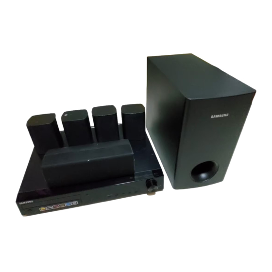
Model Name : HT-Z210
Model Code : HT-Z210T/XAH
Speaker
Front
Center
Rear
Subwoofer
Manual
HT-Z210
PS-FZ210
PS-CZ210
PS-RZ210
PS-WZ210
CONTENTS
1. Precaution
2. Product Specification
3. Disassembly & Reassembly
4. Troubleshooting
5. Exploded View & Part List
6. PCB Diagram
7. Schematic Diagram
Advertisement
Chapters
Table of Contents

Related Manuals for Samsung HT-Z210


Summary of Contents for Samsung HT-Z210
- Page 1 All manuals and user guides at all-guides.com DIGITAL HOME THEATER SYSTEM Model Name : HT-Z210 Model Code : HT-Z210T/XAH Speaker HT-Z210 Front PS-FZ210 Center PS-CZ210 Rear PS-RZ210 Subwoofer PS-WZ210 SERVICE Manual DIGITAL HOME THEATER SYSTEM CONTENTS 1. Precaution 2. Product Specification 3.
- Page 2 Asia asia.samsungportal.com Mideast & Africa mea.samsungportal.com © Samsung Electronics Co.,Ltd. Mar. 2008 This Service Manual is a property of Samsung Electronics Printed in Korea Co.,Ltd. Any unauthorized use of Manual can be punished under applicable International and/or domestic law.
-
Page 3: Table Of Contents
All manuals and user guides at all-guides.com Contents 1. Precaution 1-1 Safety Precautions ................... 1-1 1-2 Servicing Precautions ..................1-3 1-3 Precautions for Electrostatically Sensitive Devices (ESDs) ......1-4 2. Product Specification 2-1 Product Feature ....................2-1 2-2 Specifications ....................2-2 2-3 Specifications Analysis ..................2-4 2-4 Accessories ......................2-6 3. - Page 4 All manuals and user guides at all-guides.com Contents 7. Schematic Diagram 7-1 Overall Block Diagram ..................7-2 7-2 FRONT ......................7-3 7-3 BLUETOOTH ....................7-4 7-4 AMP .........................7-5 7-5 MAIN ........................7-6 7-6 MICOM ......................7-7 7-7 ANALOG ......................7-8 7-8 HDMI ........................7-9 7-9 SMPS .......................7-10...
-
Page 5: Precaution
1 and 5.2 megohms. If there is no return path, the measured resistance should be “infinite.” If the resistance is outside these limits, a shock hazard might exist. See Fig. 1-2 Samsung Electronics... - Page 6 . Use replacement components that have the same ratings, especially for flame resistance and dielectric strength specifications. A replacement part that does not have the same safety characteristics as the original might create shock, fire or other hazards. Samsung Electronics...
-
Page 7: Servicing Precautions
8. Always connect a test instrument’s ground lead to the instrument chassis ground before connecting the positive lead; always remove the instrument’s ground lead last. First read the “Safety Precautions” section of this manual. If some unforeseen circumstance creates a conflict between the servicing and safety precautions, always follow the safety precautions. Samsung Electronics... -
Page 8: Precautions For Electrostatically Sensitive Devices (Esds)
9. Minimize body motions when handing unpackaged replacement ESDs. Motions such as brushing clothes together, or lifting a foot from a carpeted floor can generate enough static electricity to damage an ESD. Samsung Electronics... -
Page 9: Product Specification
- Including HDMI CEC: HDMI Usage Expansion - Applied on Z210 and Z310 series Improved Sound Quality - Power Bass & MXF (Mutual Cross Function) → Enhanced Bass power & Shield Sound - Powered Wireless-ready → World-first 5.8GHZ (Z310) Samsung Electronics... -
Page 10: Specifications
All manuals and user guides at all-guides.com Product Specification 2-2 Specifications Basic Specification Model Name HT-Z210 Power Requirements AC 220V, 50Hz Power Consumption 80 W Weight 3.5 kg General Dimensions 430 (W) x 65 (H) x 352 (D) mm Operating Temperature Range +5°C ~ +35°C... - Page 11 266W 266W Front/Rear: 90 x 118 x 90 mm Dimensions (W x H x D) Center: 250 x 91 x 90 mm Subwoofer: 180 x 320 x 380 mm Front: 0.5 kg Center: 0.6 kg Weights Rear: 0.4 kg Subwoofer : 4.5 kg Samsung Electronics...
-
Page 12: Specifications Analysis
All manuals and user guides at all-guides.com Product Specification 2-3 Specifications Analysis HT-Z210 HT-TX500 Model Name Photo RMS (10% THD), REF: 1CH 800W 1000W Output 133W x 5 167W x 5 Power Output Power (ch) (Active Subwoofer: 133W) (Active Subwoofer: 165W) HDMI CEC Calliope Deck Horizontal Disc tray... - Page 13 All manuals and user guides at all-guides.com Product Specification HT-Z210 HT-TX500 Model Name Photo Component Composite Video Inputs S-Video HDMI In Component Composite Video HDMI Out (1080P) (1080P) Outputs S-Video SCART Out AUX1 AUX1 Line In AUX2 AUX2 Audio in/out Multi ch Out In (Digital In) ...
-
Page 14: Accessories
All manuals and user guides at all-guides.com Product Specification 2-4 Accessories 2-4-1 Supplied Accessories Accessories Item Item code Remark Remote Control AH59-01907B Batteries 4301-000116 HDMI Cable AH39-00721A Video Cable AH39-40001V Samsung Service center FM Antenna AH42-00021A Owner’s Instructions AH68-02055L Cloth Clean AH81-02286C Samsung Electronics... -
Page 15: Disassembly & Reassembly
: TAP TITE SCREW BH 3*10 BLACK <Right-Side> <Left-Side> 2) Unscrew the 3 screws from the Rear. : TAP TITE SCREW BH 3*10 BLACK 3) Lift the Top-Cover to separate it. Be careful not to make any scratches as you remove it. Samsung Electronics... - Page 16 1) Remove the wires between PCBs. In case of pulling up the PCB cable, it is easier to pull up when pressing the grip. 2) Remove the 8 screws on the PCBs. : TAP TITE SCREW BH 3*6 SILVER Samsung Electronics...
- Page 17 All manuals and user guides at all-guides.com Disassembly & Reassembly Part Name Description Description Photo CABINET- 1) Remove the remaining 5 screws in BOTTOM the rear. REAR : TAP TITE SCREW BH 3*10 BLACK 1) Picture of a disassembled product. Samsung Electronics...
- Page 18 All manuals and user guides at all-guides.com MEMO Samsung Electronics...
-
Page 19: Troubleshooting
All manuals and user guides at all-guides.com Troubleshooting 4. Troubleshooting 4-1 Checkpoints by Error Mode ..............4-2 4-2 Measures to be taken when the Protection Circuit operates ...4-25 4-3 Initialization & Upgrade Methods ............4-27 Samsung Electronics... -
Page 20: Checkpoints By Error Mode
22 of UIC1 to pin 22 of MICOM (UIC1). If short (0 ohm), Replace MICOM (UIC1) When POWER ON for Front PCB, Check for Replace the VFD DRIVER IC HIGH voltage (5V) at (ZIC1). UIC2; pin 13, 43 Samsung Electronics... - Page 21 All manuals and user guides at all-guides.com Troubleshooting Check for Circuit at SMPS Check for VFD 1, 2 ~ 61, 62 PCB D1 VFD DC 5V Check for connector from Main PCB to Front PCB; ZCON1 Samsung Electronics...
- Page 22 4, 7, 9 of BPIC1 74LCX157 VD33 is measured at the pin 1, 16 to check IPOD, BT of BPIC1. Refer to wave pattern image of Fig. 4-2. Replace the BPIC1. Check if the pin 10 and 11 of CON3 are 3.3V. Samsung Electronics...
- Page 23 70, 71, 74, 75 of MIC1 PS9829B the pin of 4, 10, 22, 29. of the AMP PCB are measured. Refer to wave pattern image of Fig. 4-4-1 and Fig. 4-4-2. Replace the MIC1. Check if the pin 22 of J7 is 3.3V. Samsung Electronics...
- Page 24 Check if the PVDD of pin 7, 8, Check if the outputs of the 9 of J3 are 34.5V. SPK1 of AMP PCB are measured. Refer to wave pattern image of Fig. 4-5. Replace the SPK1 connectors. Samsung Electronics...
- Page 25 All manuals and user guides at all-guides.com Troubleshooting IC31 ANALOG Page, 7-8 CECJ1 EIC1 AIC1 MCON15 MAIN PCB Top Page, 6-10 <Fig. 4-1> Samsung Electronics...
- Page 26 All manuals and user guides at all-guides.com Troubleshooting MAIN Page, 7-6 BPIC1 RIC4 MAIN PCB Top Page, 6-10 <Fig. 4-2> Samsung Electronics...
- Page 27 All manuals and user guides at all-guides.com Troubleshooting MIC1 IC31 MIC10 MIC3 CN10 MICOM Page, 7-7 CECJ1 BIC6 CEIC1 AIC1 MCON15 MCON12 MAIN PCB Top Page, 6-10 <Fig. 4-3> Samsung Electronics...
- Page 28 All manuals and user guides at all-guides.com Troubleshooting AMP Page, 7-5 <Fig. 4-4-1> 4-10 Samsung Electronics...
- Page 29 All manuals and user guides at all-guides.com Troubleshooting NIC1 SIC1 MIC1 AMP PCB Top Page, 6-6 <Fig. 4-4-2> Samsung Electronics 4-11...
- Page 30 All manuals and user guides at all-guides.com Troubleshooting AMP Page, 7-5 AMP PCB Top Page, 6-6 SIC1 <Fig. 4-5> 4-12 Samsung Electronics...
- Page 31 Check if the pin 3 of CON3 is Check JACK Output. Check if composite video output is measured at the JP6. Refer to wave pattern image of Fig. 4-7. Check the JP6 connectivity and replace it if necessary. Samsung Electronics 4-13...
- Page 32 All manuals and user guides at all-guides.com Troubleshooting MCON8 BPIC1 RIC4 MAIN Page, 7-6 MIC1 MIC5 MIC6 MIC10 MIC3 MAIN PCB Top Page, 6-10 CN10 <Fig. 4-6> CECJ1 4-14 Samsung Electronics...
- Page 33 All manuals and user guides at all-guides.com Troubleshooting ANALOG Page, 7-8 IC31 MAIN PCB Top Page, 6-10 AIC1 <Fig. 4-7> Samsung Electronics 4-15...
- Page 34 Fig. 4-9. Replace the VIC1. Check if the pin 12, 13 of Check JACK Output. MCON2 is 5V. Check if composite video output is measured at the VJ4. Check the VJ4 connectivity and replace it if necessary. 4-16 Samsung Electronics...
- Page 35 All manuals and user guides at all-guides.com Troubleshooting MCON8 BPIC1 RIC4 MAIN Page, 7-6 MIC1 MIC5 MIC6 MIC10 MIC3 MAIN PCB Top Page, 6-10 CN10 <Fig. 4-8> CECJ1 Samsung Electronics 4-17...
- Page 36 All manuals and user guides at all-guides.com Troubleshooting MCON8 ANALOG Page, 7-8 MAIN PCB Top Page, 6-10 IC31 <Fig. 4-9> 4-18 Samsung Electronics...
- Page 37 Fig. 4-11. Replace the IC31 IC. Check the PIC7 output pin 2 for VDD1.8V and CEIC3 output pin 2 for 3.3V Check the JK7 Output. Refer to wave pattern image of Fig. 4-12. Replace the jack. Samsung Electronics 4-19...
- Page 38 All manuals and user guides at all-guides.com Troubleshooting MCON8 BPIC1 RIC4 MAIN Page, 7-6 MIC1 MIC5 MIC6 MIC10 MIC3 MAIN PCB Top Page, 6-10 CN10 <Fig. 4-10> CECJ1 4-20 Samsung Electronics...
- Page 39 All manuals and user guides at all-guides.com Troubleshooting MCON8 IC31 ES7108S HDMI Page, 7-9 IC31 MAIN PCB Top Page, 6-10 <Fig. 4-11> Samsung Electronics 4-21...
- Page 40 All manuals and user guides at all-guides.com Troubleshooting CON8 HDMI Page, 7-9 IC31 MAIN PCB Top Page, 6-10 <Fig. 4-12> 4-22 Samsung Electronics...
- Page 41 Check DVD Signal NO DISC (MIC1 139pin DVD/CD) (MIC1 139pin DVD/CD) DISC ERROR Not Like Not Like Change DECK This This Refer to wave pattern Refer to wave pattern image of Fig. 4-13. image of Fig. 4-13. Samsung Electronics 4-23...
- Page 42 Check CD Signal Check DVD Signal Power On Position Active Check DVD Signal MAIN Page, 7-6 Power On High Position Active MIC1 MIC5 MIC6 MIC10 MIC3 MAIN PCB Top Page, 6-10 CN10 <Fig. 4-13> CECJ1 4-24 Samsung Electronics...
-
Page 43: Measures To Be Taken When The Protection Circuit Operates
+12V (1) <Table 4-1> 4-2-2 Power Protection 1. OTW: Active, IC’s inner temperature exceeds over 150°C. (Under 2.7V, Protection Circuit wills Active) 2. TAS5352 3 PIN: Shout down (Under 2.7V, Protection Circuit wills Active) <Fig. 4-14> Samsung Electronics 4-25... - Page 44 You can check AMP Malfunction before disassembling Main Unit (Do NOT Insert AC-Cord in AC-Socket) Resistance in using Tester F/R CH 10kΩ CENTER 10kΩ SUBWOOFER 10kΩ <Table 4-2> If Measured Resistance is very different from above numbers. There is a Problem. → AMP PCB Problem 5.1CH SPEAKER OUTPUT FRONT R CENTER FRONT L REAR R SUBWOOFER REAR L 4-26 Samsung Electronics...
-
Page 45: Initialization & Upgrade Methods
2. Wire to Update connector-look like an oval hole then update start. Required Equipment: Computer, Rom Writer, Connecting Cable, Update Program. Update is available Only OTP type MICOM. <Fig. 4-16 Connecting Rom writer> <Fig. 4-17 Update Program> Samsung Electronics 4-27... - Page 46 All manuals and user guides at all-guides.com Troubleshooting 4-3-2 DVD flash Initialization & Update Checking out MICOM & MPEG flash Version 1. Open DISC-TRAY, Press "MENU" button on the Remote Control. 2. Press "8", "9", "5" one by one, then press “ENTER”. <Fig. 4-18 Version> 4-28 Samsung Electronics...
- Page 47 Unit ‘NO DISC’ state. 4. Press ‘STOP’ button of Main Unit more than 5 seconds, Display Indicator shows ‘INITIALIZE’ then Power goes out. 5. Initialization complete. <Fig. 4-19 Connecting USB> <Fig. 4-20 TV Display (On Updating)> <Fig. 4-21 Update Start> Samsung Electronics 4-29...
- Page 48 All manuals and user guides at all-guides.com MEMO 4-30 Samsung Electronics...
-
Page 49: Exploded View & Part List
All manuals and user guides at all-guides.com Exploded View & Part List 5. Exploded View & Part List 5-1 Exploded View ..................5-2 5-2 Speaker System..................5-4 5-3 Electrical Part List ................5-5 Samsung Electronics This Document can not be used without Samsung’s authorization. -
Page 50: Exploded View
All manuals and user guides at all-guides.com Exploded View & Part List 5-1 Exploded View AC080 AC025 AC085 AH320 AD506 AA130 AK290 AS260 AK270 AD480 AF020 AD504 AK170 AS086 AD370 AC010 AK420 This Document can not be used without Samsung’s authorization. Samsung Electronics... - Page 51 ASSY DVD DECK-SDM-D1FL;BASIC-TYPE,CMS-S7 PCB-AMP AH92-02860A ASSY PCB-AMP;HT-Z210,AMP. ASIA PCB-FRONT AH92-02792A ASSY PCB-FRONT ASSY;HT-Z210,ASSY PCB-FRO PCB-MAIN AH92-02857A ASSY PCB-MAIN;HT-Z210,MAIN, ASIA PCB-SMPS AH44-00114A SMPS;HT-Q20,-,AC/DC,500W,110-240V,5 6003-000275 SCREW-TAPTITE;BH,+,-,B,M3,L10,ZPC(BLK),S 6003-001561 SCREW-TAPTITE;BH,+,-,B,M3,L6,ZPC(WHT),SW 6003-000280 SCREW-TAPTITE;BH,+,-,B,M3,L25,ZPC(WHT),S 6003-000276 SCREW-TAPTITE;BH,+,-,B,M3,L10,ZPC(WHT),S Samsung Electronics This Document can not be used without Samsung’s authorization.
-
Page 52: Speaker System
Rear Speaker SPEAKER-PART;PS-Z210,REAR-L SPK SYSTEM,-,-,- AH81-03990A ,-,- Rear Speaker SPEAKER-PART;PS-Z210,REAR-R SPK SYSTEM,-,- AH81-03991A ,-,-,- SPEAKER-PART; PS-Z210,SUBWOOFER SPK Subwoofer AH81-03992A SYSTEM,-,-,-,-,- SPEAKER;PS-Q20,SPK CORD,CONNECTOR,FRONT/ Speaker Wire AH81-02177B SUB W/F:4M,CENTER:3M,REAR:10M,TOTAL,35M,6 PCS,OD: 1.8*3.6(11*0.16),EXCEPT KOREA This Document can not be used without Samsung’s authorization. Samsung Electronics... -
Page 53: Electrical Part List
0501-000002 TR-SMALL SIGNAL;KSA812,PNP,150MW,SO FR1 2007-000078 R-CHIP;1Kohm,5%,1/10W,TP,1608 AH81-04001A SPEAKER-PART;PS-Z210,WOODEN CABINET FR15 2007-000075 R-CHIP;220ohm,5%,1/10W,TP,1608 AH81-04002A SPEAKER-PART;PS-Z210,CUSHION-TOP-SU FR16 2007-000309 R-CHIP;10ohm,5%,1/10W,TP,1608 AH81-04003A SPEAKER-PART;PS-Z210,CUSHION-BOTTOM FR17 2007-000090 R-CHIP;10Kohm,5%,1/10W,TP,1608 FR18 2007-000090 R-CHIP;10Kohm,5%,1/10W,TP,1608 AH97-02152U ASSY MACHINERY-POWER CORD;160MM,007 1 FR19 2007-000070 R-CHIP;0ohm,5%,1/10W,TP,1608 3301-000132 CORE-FERRITE;AC,28.8x19.3x7.5mm,140 Samsung Electronics This Document can not be used without Samsung’s authorization. - Page 54 0501-000422 TR-SMALL SIGNAL;KTA1273,PNP,-30V,-3 AH81-02639A DIODE-BRIDGE;GBU605G,600V,6A,GBU,-, 0501-000630 TR-SMALL SIGNAL;KTA1268,PNP,300MW,T AH81-02642A C-FILM MPEF-MYLAR;0.0047uF,100V,5%, AH81-02643A C-FILM MPEF-MYLAR;0.0082uF,100V,5%, 1203-002597 IC-PWM CONTROLLER;KA5Q1265RF-YDTU,T AH81-02647A C-CERAMIC DISK;470pF,400VAC-Y1,20%, 1203-003365 IC-PWM CONTROLLER;FSDM0365RNC,DIP,8 1203-004573 IC-VOL. REFERANCE;FAN431A,TO-92,3P, AH81-02650A C-CERAMIC DISK;2200pF,400VAC-Y1,20% 2001-000003 R-CARBON;330ohm,5%,1/8W,AA,TP,1.8x3 AH81-02651A C-AL;6800uF,6.3V,12.5*25mm,-40 to + 2001-000302 R-CARBON;10OHM,5%,1/8W,AA,TP,1.8X3. AH81-02652A C-AL;330uF,10V,6.3*11mm,-40 to +85C AH81-02654A C-AL;1000uF,10V,10*12.5mm,-40 to +8 This Document can not be used without Samsung’s authorization. Samsung Electronics...
- Page 55 2203-000280 C-CER,CHIP;0.01nF,0.5pF,50V,C0G,160 EBD16 3301-001495 BEAD-SMD;120ohm,2012,2500mA,TP,115o EBD2 3301-001495 BEAD-SMD;120ohm,2012,2500mA,TP,115o CC14 2203-000280 C-CER,CHIP;0.01nF,0.5pF,50V,C0G,160 EBD3 3301-001495 BEAD-SMD;120ohm,2012,2500mA,TP,115o CEC1 2203-005148 C-CER,CHIP;100nF,10%,16V,X7R,TP,160 CEC42 2203-005148 C-CER,CHIP;100nF,10%,16V,X7R,TP,160 EBD4 3301-001495 BEAD-SMD;120ohm,2012,2500mA,TP,115o CEC43 2401-000240 C-AL;100uF,20%,10V,GP,TP,5x11,5 EBD9 3301-001495 BEAD-SMD;120ohm,2012,2500mA,TP,115o Samsung Electronics This Document can not be used without Samsung’s authorization.
- Page 56 HL08 2007-000070 R-CHIP;0ohm,5%,1/10W,TP,1608 HR59 2007-000084 R-CHIP;4.7Kohm,5%,1/10W,TP,1608 HL09 3301-001495 BEAD-SMD;120ohm,2012,2500mA,TP,115o HL10 2901-001302 FILTER-EMI SMD;20V,0.3A,0pF,2.0x1.2 HR60 2007-000084 R-CHIP;4.7Kohm,5%,1/10W,TP,1608 HL11 2901-001302 FILTER-EMI SMD;20V,0.3A,0pF,2.0x1.2 HR61 2007-000074 R-CHIP;100ohm,5%,1/10W,TP,1608 HL12 2901-001302 FILTER-EMI SMD;20V,0.3A,0pF,2.0x1.2 HR62 2007-000074 R-CHIP;100ohm,5%,1/10W,TP,1608 H-SINK AH62-00062G HEAT SINK-TR;HT-DS400,AL EXTR,-,-,- This Document can not be used without Samsung’s authorization. Samsung Electronics...
- Page 57 2203-005148 C-CER,CHIP;100nF,10%,16V,X7R,TP,160 MR113 2007-000309 R-CHIP;10ohm,5%,1/10W,TP,1608 MC39 2203-005148 C-CER,CHIP;100nF,10%,16V,X7R,TP,160 MR114 2007-000309 R-CHIP;10ohm,5%,1/10W,TP,1608 MC40 2203-000646 C-CER,CHIP;0.024NF,5%,50V,C0G,TP,16 MR12 2011-000816 R-NETWORK;100ohm,5%,1/16W,L,CHIP,8P MR120 2007-000081 R-CHIP;2.7Kohm,5%,1/10W,TP,1608 MC41 2203-000681 C-CER,CHIP;0.027nF,5%,50V,C0G,1608 MR121 2007-000074 R-CHIP;100ohm,5%,1/10W,TP,1608 MC42 2203-005148 C-CER,CHIP;100nF,10%,16V,X7R,TP,160 Samsung Electronics This Document can not be used without Samsung’s authorization.
- Page 58 2007-000070 R-CHIP;0ohm,5%,1/10W,TP,1608 RB1A 3301-001495 BEAD-SMD;120ohm,2012,2500mA,TP,115o RC01 2401-001355 C-AL;470uF,20%,10V,GP,TP,8x11.5mm,5 MR86 2007-000070 R-CHIP;0ohm,5%,1/10W,TP,1608 RC02 2203-000257 C-CER,CHIP;10nF,10%,50V,X7R,TP,1608 MR89 2007-000113 R-CHIP;33ohm,5%,1/10W,TP,1608 MR90 2007-000113 R-CHIP;33ohm,5%,1/10W,TP,1608 RC03 2203-000189 C-CER,CHIP;100nF,+80-20%,25V,Y5V,16 MR91 2007-000113 R-CHIP;33ohm,5%,1/10W,TP,1608 RC07 2401-000042 C-AL;100uF,20%,16V,GP,TP,6.3x7,5 5-10 This Document can not be used without Samsung’s authorization. Samsung Electronics...
- Page 59 2007-000113 R-CHIP;33ohm,5%,1/10W,TP,1608 RR93 2007-000097 R-CHIP;47Kohm,5%,1/10W,TP,1608 RR13 2007-000094 R-CHIP;22Kohm,5%,1/10W,TP,1608 RR14 2007-000070 R-CHIP;0ohm,5%,1/10W,TP,1608 RR94 2007-000097 R-CHIP;47Kohm,5%,1/10W,TP,1608 RR15 2007-000087 R-CHIP;6.8Kohm,5%,1/10W,TP,1608 RR95 2007-000097 R-CHIP;47Kohm,5%,1/10W,TP,1608 RR24 2007-000092 R-CHIP;15Kohm,5%,1/10W,TP,1608 RR97 2007-000098 R-CHIP;56Kohm,5%,1/10W,TP,1608 RR98 2007-000130 R-CHIP;39Kohm,5%,1/10W,TP,1608 Samsung Electronics This Document can not be used without Samsung’s authorization. 5-11...
- Page 60 2007-000078 R-CHIP;1Kohm,5%,1/10W,TP,1608 UR80 2007-000074 R-CHIP;100ohm,5%,1/10W,TP,1608 UR20 2007-000074 R-CHIP;100ohm,5%,1/10W,TP,1608 UR81 2007-000074 R-CHIP;100ohm,5%,1/10W,TP,1608 UR20A 2007-000090 R-CHIP;10Kohm,5%,1/10W,TP,1608 UR82 2007-000074 R-CHIP;100ohm,5%,1/10W,TP,1608 UR83 2007-000074 R-CHIP;100ohm,5%,1/10W,TP,1608 UR20C 2007-000090 R-CHIP;10Kohm,5%,1/10W,TP,1608 UR84 2007-000074 R-CHIP;100ohm,5%,1/10W,TP,1608 UR21 2007-000074 R-CHIP;100ohm,5%,1/10W,TP,1608 5-12 This Document can not be used without Samsung’s authorization. Samsung Electronics...
- Page 61 2007-001167 R-CHIP;75ohm,5%,1/10W,TP,1608 ZAR12 2007-000094 R-CHIP;22Kohm,5%,1/10W,TP,1608 ZAR19 2007-000074 R-CHIP;100ohm,5%,1/10W,TP,1608 VR59 2007-000090 R-CHIP;10Kohm,5%,1/10W,TP,1608 ZAR2 2007-000102 R-CHIP;100Kohm,5%,1/10W,TP,1608 VR6 2007-001167 R-CHIP;75ohm,5%,1/10W,TP,1608 VR66 2007-001167 R-CHIP;75ohm,5%,1/10W,TP,1608 ZAR24 2007-000074 R-CHIP;100ohm,5%,1/10W,TP,1608 VR7 2007-001167 R-CHIP;75ohm,5%,1/10W,TP,1608 ZAR25 2007-000074 R-CHIP;100ohm,5%,1/10W,TP,1608 Samsung Electronics This Document can not be used without Samsung’s authorization. 5-13...
- Page 62 2203-005249 C-CER,CHIP;100nF,10%,50V,X7R,1608 C16RL 2203-000257 C-CER,CHIP;10nF,10%,50V,X7R,TP,1608 C42FR 2203-005249 C-CER,CHIP;100nF,10%,50V,X7R,1608 C16SW 2203-000257 C-CER,CHIP;10nF,10%,50V,X7R,TP,1608 C17C 2203-005249 C-CER,CHIP;100nF,10%,50V,X7R,1608 C43FR 2203-005249 C-CER,CHIP;100nF,10%,50V,X7R,1608 C17FL 2203-005249 C-CER,CHIP;100nF,10%,50V,X7R,1608 C44FR 2203-005249 C-CER,CHIP;100nF,10%,50V,X7R,1608 C17FR 2203-005249 C-CER,CHIP;100nF,10%,50V,X7R,1608 C45FR 2203-005249 C-CER,CHIP;100nF,10%,50V,X7R,1608 5-14 This Document can not be used without Samsung’s authorization. Samsung Electronics...
- Page 63 0401-001090 DIODE-SWITCHING;1SS355,80V,100MA,SO FD2 0401-001090 DIODE-SWITCHING;1SS355,80V,100MA,SO MC27 2203-005249 C-CER,CHIP;100nF,10%,50V,X7R,1608 FJ1 3711-000820 HEADER-BOARD TO CABLE;BOX,2P,1R,2.5 MC28 2401-001355 C-AL;470uF,20%,10V,GP,TP,8x11.5mm,5 FQ1 0501-000422 TR-SMALL SIGNAL;KTA1273,PNP,-30V,-3 MC29 2203-005249 C-CER,CHIP;100nF,10%,50V,X7R,1608 MC3 2203-005249 C-CER,CHIP;100nF,10%,50V,X7R,1608 FQ2 0501-000341 TR-SMALL SIGNAL;KSC1623-L,NPN,200mW MC30 2203-005249 C-CER,CHIP;100nF,10%,50V,X7R,1608 Samsung Electronics This Document can not be used without Samsung’s authorization. 5-15...
- Page 64 2007-000052 R-CHIP;10Kohm,1%,1/10W,TP,1608 R24FR 2007-000070 R-CHIP;0ohm,5%,1/10W,TP,1608 MR9 2007-000052 R-CHIP;10Kohm,1%,1/10W,TP,1608 R2C 2007-000312 R-CHIP;10ohm,5%,1/4W,TP,3216 R2FL 2007-000312 R-CHIP;10ohm,5%,1/4W,TP,3216 MX1 2801-004354 CRYSTAL-UNIT;12.288MHZ,30PPM,ATS-49 R2FR 2007-000312 R-CHIP;10ohm,5%,1/4W,TP,3216 NC6 2401-001020 C-AL;3.3UF,20%,50V,GP,TP,4X7,5 NC7 2401-000048 C-AL;47uF,20%,25V,GP,TP,5x11,5 R2RL 2007-000312 R-CHIP;10ohm,5%,1/4W,TP,3216 5-16 This Document can not be used without Samsung’s authorization. Samsung Electronics...
- Page 65 4301-000116 BATTERY-ALKALINE;9V,-,-,17.5x26.5x4 6801-001233 CARD-WARRANTY;COLOMBIA,SAMCOL,SPANI 1 6902-000385 BAG PE;LDPE,T0.03,W250,L350,TRP,8,1 AH39-00721A CBF MODULE CABLE;HT-DS1000,19,3000, AH39-40001V CABLE-AUDIO CABLE;-,-,1P-1P,3000mm, AH42-00021A ANT FM T;T18011F-1,75 ohm,1800mm AH68-02055L MANUAL USERS;HT-Z310,XAP,ES,-,MOJO8 AH68-50254B LABEL-SERIAL;ART PAPER,T0.1,L10,W45 1.05 SNA AH81-02286C A/S-EYEGLASS CLOTH;HT-TXQ120,POLY-B AH59-01907B REMOCON-ASSY;HT-Z210/EXP,SAMSUNG,23 AH69-02160B MASTER CARTON;HT-Z210,PPR-OTH,T7,W5 1.02 SNA AH97-01831A ASSY DVD DECK-SDM-D1FL;BASIC-TYPE,C Samsung Electronics This Document can not be used without Samsung’s authorization. 5-17...
- Page 66 All manuals and user guides at all-guides.com MEMO 5-18 Samsung Electronics...
-
Page 67: Pcb Diagram
6. PCB Diagram 6-1 Wiring Diagram....................6-2 6-2 FRONT PCB Top ....................6-3 6-3 FRONT PCB Bottom ..................6-5 6-4 AMP PCB Top ....................6-6 6-5 AMP PCB Bottom ..................... 6-8 6-6 BLUETOOTH PCB Top ..................6-9 6-7 BLUETOOTH PCB Bottom ................6-9 6-8 MAIN PCB Top ....................6-10 6-9 MAIN PCB Bottom .................... 6-13 6-10 SMPS PCB Top ....................6-14 Samsung Electronics... -
Page 68: Wiring Diagram
OUTSW OUTSW D_5V D_5V CLOSE CLOSE D_5V D_5V OPEN OPEN M8_GND M8_GND M_8V M_8V CN02 MCON2 MCON3 FCON1 ST-BY FRONT ASSY ASSY DGND DGND PLED2 PLED2 PLED1 PLED1 P/SW P/SW LED 5V LED 5V A_SENSE A_SENSE FCW2 FCON2 Samsung Electronics... -
Page 69: Front Pcb Top
All manuals and user guides at all-guides.com PCB Diagram 6-2 FRONT PCB Top FCON1 KIC1 KIC2 FCON2 KCW2 FCW3 Samsung Electronics... - Page 70 Pin No. Signal Pin No. Signal REMOCON DATA- VOLUME UP DATA+ VOLUME DOWN PWR_LED1 AUDIO_R PWR_LED2 +5.6V AUDIO_L DGND +12V AGND SCORE +ADC MIC SENSE MIC MUTE AGND VFD -4.3V VFD +4.3V VFD GND CE(VFD) DO(VFD) CLK(VFD) A_SENSE +12V ASC_SENS Samsung Electronics...
-
Page 71: Front Pcb Bottom
All manuals and user guides at all-guides.com PCB Diagram 6-3 FRONT PCB Bottom FCON1 KIC2 FCON2 KCW2 FCW3 Samsung Electronics... -
Page 72: Amp Pcb Top
All manuals and user guides at all-guides.com PCB Diagram 6-4 AMP PCB Top NIC1 SIC1 MIC1 Samsung Electronics... - Page 73 Signal Pin No. Signal SCART_R +12V SCART_L AGND -12V TI_SD TI_RST 3.3V_GND +3.3V PVDD PWM EXT_MUTE PVDD D_GND PVDD TI_CHECK PWM_DO PWM_CLK PWM_DI PWM_CS PWM_RST TSD2 TSD1 TSD0 TBCK LRCLK D+5V +12V -12V A_GND FAN CHK MIC_IN FAN_POWER FAN_SD Samsung Electronics...
-
Page 74: Amp Pcb Bottom
All manuals and user guides at all-guides.com PCB Diagram 6-5 AMP PCB Bottom Samsung Electronics... -
Page 75: Bluetooth Pcb Top
All manuals and user guides at all-guides.com PCB Diagram 6-6 BLUETOOTH PCB Top 6-7 BLUETOOTH PCB Bottom CON1 Samsung Electronics... -
Page 76: Main Pcb Top
All manuals and user guides at all-guides.com PCB Diagram 6-8 MAIN PCB Top MCON8 BPIC1 RIC4 TP12 TP11 TP10 TP15 TP16 MIC1 TP14 TP13 UIC1 IC31 TP13 MIC5 TP10 MIC6 TP11 TP12 MIC10 MIC3 CN10 CECJ1 BIC6 CEIC1 AIC1 MCON15 MCON2 MCON12 6-10 Samsung Electronics... - Page 77 TSD0 RF GND INSW CE(VFD) TBCK MVREF DO(VFD) LRCLK RF50V OUTSW CLK(VFD) D+5V CLOSE A_SENSE +12V OPEN -12V CDVR A_GND DVDVR 4 CN01 FAN CHK MECHA Control Connector CDLDO MIC_IN Pin No. Signal FAN_POWER RF50V FAN_SD DVDLDO RFGND Samsung Electronics 6-11...
- Page 78 All manuals and user guides at all-guides.com PCB Diagram 6-8-2 Test Point Wave Form TP14 TP15 TP10 TP11 TP16 TP12 TP13 6-12 Samsung Electronics...
-
Page 79: Main Pcb Bottom
All manuals and user guides at all-guides.com PCB Diagram 6-9 MAIN PCB Bottom MCON8 CN10 CECJ1 MCON2 MCON12 Samsung Electronics 6-13... -
Page 80: Smps Pcb Top
All manuals and user guides at all-guides.com PCB Diagram 6-10 SMPS PCB Top 6-14 Samsung Electronics... -
Page 81: Schematic Diagram
7-3 BLUETOOTH ..................... 7-4 7-4 AMP ........................7-5 7-5 MAIN ........................7-6 7-6 MICOM ....................... 7-7 7-7 ANALOG ......................7-8 7-8 HDMI ........................7-9 7-9 SMPS ......................... 7-10 Samsung Electronics This Document can not be used without Samsung’s authorization. -
Page 82: Overall Block Diagram
The Power supplies voltages for each component using the SMPS. The Power can be switched turned on or off through the Micom port. The functions and DPL2 function can be controlled by the front keypad and remote control. DRAM M12L12816B FLASH AT26DF161A 24C08A This Document can not be used without Samsung’s authorization. Samsung Electronics... -
Page 83: Front
All manuals and user guides at all-guides.com Schematic Diagram 7-2 FRONT POWER Samsung Electronics This Document can not be used without Samsung’s authorization. -
Page 84: Bluetooth
All manuals and user guides at all-guides.com Schematic Diagram 7-3 BLUETOOTH POWER This Document can not be used without Samsung’s authorization. Samsung Electronics... -
Page 85: Amp
All manuals and user guides at all-guides.com Schematic Diagram 7-4 AMP Samsung Electronics This Document can not be used without Samsung’s authorization. -
Page 86: Main
All manuals and user guides at all-guides.com Schematic Diagram 7-5 MAIN TP15 POWER AUDIO VIDEO TP16 TP16 TP15 TP12 TP11 TP10 TP13 TP10 TP12 TP11 TP13 This Document can not be used without Samsung’s authorization. Samsung Electronics... -
Page 87: Micom
All manuals and user guides at all-guides.com Schematic Diagram 7-6 MICOM POWER Samsung Electronics This Document can not be used without Samsung’s authorization. -
Page 88: Analog
All manuals and user guides at all-guides.com Schematic Diagram 7-7 ANALOG POWER AUDIO VIDEO TP10 TP12 TP11 TP12 TP10 TP11 This Document can not be used without Samsung’s authorization. Samsung Electronics... -
Page 89: Hdmi
All manuals and user guides at all-guides.com Schematic Diagram 7-8 HDMI POWER AUDIO VIDEO HDMI OUT TP13 IC31 ES7108S TP14 TP13 TP14 Samsung Electronics This Document can not be used without Samsung’s authorization. -
Page 90: Smps
All manuals and user guides at all-guides.com Schematic Diagram 7-9 SMPS 7-10 This Document can not be used without Samsung’s authorization. Samsung Electronics...