Siemens 3RP25 Manual
Monitoring and control devices. time relays
Hide thumbs
Also See for 3RP25:
- Operating instructions manual (6 pages) ,
- Operating instructions manual (6 pages)
Table of Contents
Advertisement
3RP25 Time Relays
Industrial controls
Monitoring and control devices
3RP25 Time Relays
Manual
09/2019
A5E31947765002A/RS-AC/003
Introduction
Safety notes
Description
Mounting
Connection
Single function devices
Multifunction units
Technical data
Dimension drawings
Spare parts/accessories
1
2
3
4
5
6
7
8
9
10
Advertisement
Table of Contents

Related Manuals for Siemens 3RP25


Summary of Contents for Siemens 3RP25
- Page 1 3RP25 Time Relays Introduction Safety notes Industrial controls Description Mounting Monitoring and control devices 3RP25 Time Relays Connection Single function devices Manual Multifunction units Technical data Dimension drawings Spare parts/accessories 09/2019 A5E31947765002A/RS-AC/003...
- Page 2 Note the following: WARNING Siemens products may only be used for the applications described in the catalog and in the relevant technical documentation. If products and components from other manufacturers are used, these must be recommended or approved by Siemens. Proper transport, storage, installation, assembly, commissioning, operation and maintenance are required to ensure that the products operate safely and without any problems.
-
Page 3: Table Of Contents
Device versions ........................15 Special features ........................17 Notes on configuration ......................19 Area of application ........................20 Overview of 3RP25 components and accessories ..............22 Mounting ..............................23 Warning notices ........................23 Terminal coding ........................24 Mounting the devices on a standard mounting rail ..............25 Removing devices from a standard mounting rail .............. - Page 4 Structure ..........................65 Time setting multifunction unit ....................66 Function table multifunction (3RP2505) ................. 69 Technical data ............................83 Technical data in Siemens Industry Online Support .............. 83 Dimension drawings ..........................85 Dimension drawings 3RP25 devices ..................85 Spare parts/accessories .......................... 89 10.1...
-
Page 5: Introduction
Online Support The Online Support in the Service&Support portal is an extensive information system for all questions relating to Siemens products and solutions. This service enables direct and central access to in-depth information concerning the products, systems and applications for industry and to a large number of programming, configuration and application examples. - Page 6 ● Background and system descriptions ● Performance statements ● Demonstration systems/videos Link: Applications & Tools (http://support.automation.siemens.com/WW/view/de/20208582) My Documentation Manager My Documentation Manager enables you to compile your own documentation from our standard documents (manuals), which are located in the Product Support section. Under mySupport, you have the opportunity to create and manage you own compilations in a structure of their own.
-
Page 7: Datamatrix Code
(http://support.automation.siemens.com), such as operating instructions, manuals, data sheets, FAQs, etc. We provide the SIEMENS Industry Support app free for this purpose and it can be used on most commercially available smartphones and tablets. The SIEMENS Industry Support app is available for iOS and Android-based devices and can... -
Page 8: Standards/Regulations/Approvals
● EN 61000-6-2 and EN 61000-6-4 "Electromagnetic compatibility" UL/CSA/Shipbuilding approval (applied for, for the current status see the Product Data Sheet in the Siemens Industry Mall) SIRIUS time relays have UL and CSA approval for use all over the world. They have also been prototype-tested by the GL, LRS, and DNV shipbuilding companies. -
Page 9: Connection
50/60 Hz AC Frequency ☐ range 50/60 Hz AC/DC Example 3 R P 2 5 Multifunction relays with 7 time ranges; screw-type terminals; 1 CO relay contact; 12 ... 240 V AC/DC; 50/60 Hz 3RP25 Time Relays Manual, 09/2019, A5E31947765002A/RS-AC/003... - Page 10 Introduction 1.6 Article No. scheme 3RP25 Time Relays Manual, 09/2019, A5E31947765002A/RS-AC/003...
-
Page 11: Safety Notes
Changes to the system configuration and wiring are only permissible while the supply voltage is switched off. Connection of 3RP25 time relays is only permissible when the power supply is switched off. 3RP25 Time Relays Manual, 09/2019, A5E31947765002A/RS-AC/003... -
Page 12: Intended Use
Intended Use of Hardware Products This equipment is only allowed to be used for the applications described in the catalog and in the technical description, and only in conjunction with non-Siemens equipment and components recommended by Siemens. Correct transport, storage, installation and assembly, as well as careful operation and maintenance, are required to ensure that the product operates safely and without faults. -
Page 13: Description
Description Device overview 3RP25 Time Relays Manual, 09/2019, A5E31947765002A/RS-AC/003... -
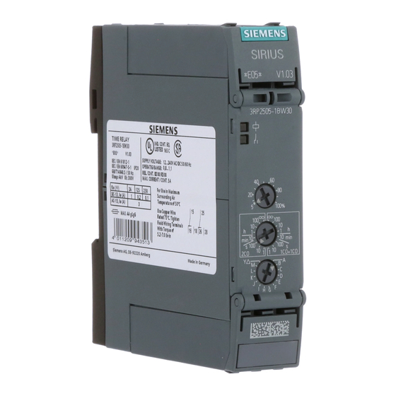
Page 14: Device Description
SIRIUS 3RP timing relays ideal modules for control cabinet, switchgear and control manufacturers in the industry. Thanks to their slim-line, space-saving design from 17.5 mm, 3RP25 timing relays are especially suitable for use in smaller control boxes, such as heating, ventilation and air- conditioning systems, and in compressors. -
Page 15: Device Versions
The overall height of 100 mm has been standardized with the other system components, and the overall depth has been standardized for all widths to 90 mm. Refer to Section "Dimension drawings 3RP25 devices (Page 85)" for the precise dimensions. The timing relays are designed in two widths: ●... - Page 16 M (GND) Retriggerable interval relay with Retriggerable interval relay with activated and instantaneous contact activated control signal (watchdog) control signal (watchdog) Star-delta (wye-delta) function 3RP25 Time Relays Manual, 09/2019, A5E31947765002A/RS-AC/003...
-
Page 17: Special Features
The electrical service life at 230 V AC voltage, utilization category AC-15/3 A is 100 000 operating cycles. Start/control contact With functions requiring a continuously active supply voltage at terminals A1/A2, the timer function is started by a control signal at terminal B1. 3RP25 Time Relays Manual, 09/2019, A5E31947765002A/RS-AC/003... - Page 18 ● With the "OFF-delay without control signal" function, timing is started when the time relay is disconnected from the supply voltage. ● On the 3RP25 time relay with 7 switchable time ranges, there is a switch position ∞. This means "continuous (unlimited) time". If this setting is selected with the "ON-delay"...
-
Page 19: Notes On Configuration
Never apply both control voltages simultaneously. Parallel load at the start contact A circuit with parallel load is permissible with AC and DC on the 3RP25 timing relays. Positively-driven contacts When using positively driven contacts with 3RP2502-xRW30, the same power supply / voltage must be used for both changeover contacts. -
Page 20: Area Of Application
● Time relay with which the timing period starts when the supply voltage and the control signal are applied, and the output briefly switches to the working position after expiry of the set time delay 3RP25 Time Relays Manual, 09/2019, A5E31947765002A/RS-AC/003... - Page 21 ● Closed-loop control (pre-travel and overtravel) of heating or cooling systems Passing make contact ● Forced ventilation of rooms ● Stairwell lighting and elevator lighting Passing break contact ● Emptying a conveyor belt / chip conveyor at end of process 3RP25 Time Relays Manual, 09/2019, A5E31947765002A/RS-AC/003...
-
Page 22: Overview Of 3Rp25 Components And Accessories
Description 3.7 Overview of 3RP25 components and accessories Overview of 3RP25 components and accessories ① Basic unit ② Top cover flap ③ Bottom cover flap ④ Spring-loaded terminals (push-in) 2-pole 1 x 2.5 mm² ⑤ Screw-type terminals 2-pole 1 x 2.5 mm²... -
Page 23: Mounting
Causes electric shock and burns when touched. Turn off and lock out all power supplying this device before working on this device. Note Following figures similar! The figures shown below (size, accessories, add-ons, etc.) are similar. 3RP25 Time Relays Manual, 09/2019, A5E31947765002A/RS-AC/003... -
Page 24: Terminal Coding
Mounting 4.2 Terminal coding Terminal coding You can provide the terminals with coding pins (3ZY1440-1AA00). This helps you to avoid errors when replacing the terminals. 3RP25 Time Relays Manual, 09/2019, A5E31947765002A/RS-AC/003... -
Page 25: Mounting The Devices On A Standard Mounting Rail
The figures show 22.5 mm devices. The 17.5 mm devices are mounted correspondingly. Step Instructions Figure Hang the back of the device onto the upper edge of the standard mounting rail Press the lower half of the device against the rail until the device engages 3RP25 Time Relays Manual, 09/2019, A5E31947765002A/RS-AC/003... -
Page 26: Removing Devices From A Standard Mounting Rail
● The terminals have been removed or disconnected. Procedure Step Instructions Figure Press the device downwards. Pull the lower half of the device away from the standard mounting rail. Lift the device from the upper edge of the standard mounting rail. 3RP25 Time Relays Manual, 09/2019, A5E31947765002A/RS-AC/003... -
Page 27: Mounting The Devices On A Level Surface
● Two properly executed drill holes with thread or plug on the level surface. For details of the distances between the drilled holes, please refer to the relevant dimension drawings in the chapter "Dimension drawings 3RP25 devices (Page 85)". ● Two screws to fit the M4 x 12 holes in accordance with DIN 784. -
Page 28: Disassembling The Devices From A Level Surface
● The terminals have been removed or disconnected. Procedure Step Instructions Figure Hold the device firmly. Unscrew the cap screws. Lift the device from the level surface. Remove the securing brackets from the device. 3RP25 Time Relays Manual, 09/2019, A5E31947765002A/RS-AC/003... -
Page 29: Mounting The Sealable Cover
Instructions Figure Attach the hooks on the cover to the openings on the device and fold the cover up Seal the cover to secure it against unauthorized removal. Sealing wire diameter, max.: 2 mm 3RP25 Time Relays Manual, 09/2019, A5E31947765002A/RS-AC/003... -
Page 30: Attaching Set Of Labels (Multifunction)
Take the corresponding sticker for labeling the function from the set of stickers, and stick it directly above the function selector switch (A-M). Function, see Function table multifunction (3RP2505) (Page 69) 3RP25 Time Relays Manual, 09/2019, A5E31947765002A/RS-AC/003... -
Page 31: Connection
The position of the label corresponds to the position of the respective terminal. NOTICE Risk of property damage When using the terminal blocks, you must observe the correct position of the blocks (see inside of cover). Figure 5-1 Upper terminal cover 3RP25 Time Relays Manual, 09/2019, A5E31947765002A/RS-AC/003... - Page 32 Connection 5.1 Terminal assignment Figure 5-2 Lower terminal cover 3RP25 Time Relays Manual, 09/2019, A5E31947765002A/RS-AC/003...
- Page 33 Connection 5.1 Terminal assignment Terminal cover Depending on the version of the 3RP25 time relay, the device will have the following connections: Time relay version Inscription of the terminal cover Control circuit/control circuit supply (at the top of the device) Single function •...
- Page 34 Connection 5.1 Terminal assignment Time relay version Inscription of the terminal cover Output contacts/output relays (at the bottom of the device) Single and multifunction 3RP25 Time Relays Manual, 09/2019, A5E31947765002A/RS-AC/003...
-
Page 35: Position Of The Connecting Terminals
① ② ③ ④ ⑤ 3RP2505 - .AB30 3RP2535 - .AW30 3RP2511 - .AW30 3RP2527 - .EW30 3RP2560 - .SW30 3RP2505 - .AW30 3RP2512 - .AW30 3RP2513 - .AW30 3RP2525 - .AW30 3RP25 Time Relays Manual, 09/2019, A5E31947765002A/RS-AC/003... - Page 36 ⑦ ⑧ ⑨ ⑩ 3RP2574 - .NW30 3RP2540 - .AB30 3RP2540 - .BB30 3RP2505 - .BB30 3RP2525 - .BB30 3RP2576 - .NW30 3RP2540 - .AW30 3RP2540 - .BW30 3RP2505 - .BW30 3RP2525 - .BW30 3RP25 Time Relays Manual, 09/2019, A5E31947765002A/RS-AC/003...
- Page 37 Connection 5.2 Position of the connecting terminals ⑪ ⑫ ⑬ ⑭ ⑮ 3RP2574 - .NM20 3RP2555 - .AW30 3RP2505 - .CW30 3RP2505 - .BT20 3RP2505-.RW30 3RP2576 - .NM20 3RP25 Time Relays Manual, 09/2019, A5E31947765002A/RS-AC/003...
-
Page 38: Connection Data For Terminals
2 x 20 ... 14 When 2 x 1.0 mm² end sleeves with a plastic sleeve are used, space problems may arise with the sleeves; as an alternative, you are advised to use end sleeves without plastic sleeves 3RP25 Time Relays Manual, 09/2019, A5E31947765002A/RS-AC/003... -
Page 39: Connecting The Screw-Type Terminals
Insert the relevant cable into square on the screw-type terminal until it engages. Hold the cable in the screw-type terminal. Tighten the screw with a torque of 0.8 to 1.2 N. Pull on the cable to ensure it is screwed tight. 3RP25 Time Relays Manual, 09/2019, A5E31947765002A/RS-AC/003... -
Page 40: Disconnecting The Screw-Type Terminals
Before starting work, therefore, disconnect the system and devices from the power supply. Requirements ● Cross-tip screwdriver size PZ 1 x 80 Procedure Step Instructions Figure Unscrew the screw of the screw-type terminal. Remove the cable from the unscrewed screw-type terminal. 3RP25 Time Relays Manual, 09/2019, A5E31947765002A/RS-AC/003... -
Page 41: Wiring Rules For Spring-Loaded Terminals (With Push-In Technology)
When use is made of a cable that utilizes the full overall height, the terminal's spring is deflected to the maximum. Therefore, removal of this cable may become a problem because it requires further deflection of the spring. 3RP25 Time Relays Manual, 09/2019, A5E31947765002A/RS-AC/003... -
Page 42: Connect The Spring-Loaded Terminal (Push-In)
Table 5- 1 Rigid conductors or conductors equipped with end sleeves Step Instructions Figure Insert the cable into the oval opening as far as it will go. Pull on the cable to ensure it is tight. 3RP25 Time Relays Manual, 09/2019, A5E31947765002A/RS-AC/003... - Page 43 Insert the screwdriver in the rectangular opening to open the terminal (oval opening). Insert the cable as far as it will go into the oval opening and remove the screwdriver. Pull on the cable to ensure it is tight. 3RP25 Time Relays Manual, 09/2019, A5E31947765002A/RS-AC/003...
-
Page 44: Disconnect The Spring-Loaded Terminal (Push-In)
● Screwdriver DIN 5264 of the size 0.5 x 3 mm Procedure Step Instructions Figure Insert the screwdriver into the rectangular opening of the spring-loaded terminal until it engages. Remove the cable from the oval opening. Remove the screwdriver. 3RP25 Time Relays Manual, 09/2019, A5E31947765002A/RS-AC/003... -
Page 45: Attaching The Terminals
You must have removed the terminals, for the purpose of replacing a device, for example. Procedure when plugging in the terminals Step Instructions Figure Insert the detachable terminals into the guide rail of the device. Slide the detachable terminals back until they audibly engage. 3RP25 Time Relays Manual, 09/2019, A5E31947765002A/RS-AC/003... -
Page 46: Removing The Terminals
Before starting work, therefore, disconnect the system and devices from the power supply. Removing terminals from the device Step Instructions Figure Press the clip of the terminals upwards. Pull the terminals out to the front. Lift the terminals out of the guide rail of the device. 3RP25 Time Relays Manual, 09/2019, A5E31947765002A/RS-AC/003... - Page 47 Insert the screwdriver into the rectangular opening of the push-in terminal until it engages. Please observe a 10° horizontal angular deviation of the screwdriver to the oval opening. Remove the cable from the oval opening. Remove the screwdriver. 3RP25 Time Relays Manual, 09/2019, A5E31947765002A/RS-AC/003...
- Page 48 Connection 5.10 Removing the terminals 3RP25 Time Relays Manual, 09/2019, A5E31947765002A/RS-AC/003...
-
Page 49: Single Function Devices
Terminal cover top, inscription on inside ⑩ Control supply voltage specification ⑪ Terminal labeling of the control supply voltage ⑫ Terminal cover top, inscription on inside ⑬ Terminal labeling of the output contacts ⑭ Time relay article number (MLFB) 3RP25 Time Relays Manual, 09/2019, A5E31947765002A/RS-AC/003... -
Page 50: Time Setting Single Function Unit
Turn the operating time adjustment switch for fine adjustment to 50 %. This means 50 % of the maximum value (50 % of 100 seconds = 50 seconds) is set. Operating time adjustment switch 3RP25 Time Relays Manual, 09/2019, A5E31947765002A/RS-AC/003... -
Page 51: On-Delay
● 0.5 s - 10 s (3RP2511) ● 1.5 s - 30 s (3RP2512) ● 5 s - 100 s (3RP2513) Function table Function Function chart Circuit diagram Time relay 1 CO contact ON-delay 3RP2511-.AW30 3RP2512-.AW30 3RP2513-.AW30 3RP25 Time Relays Manual, 09/2019, A5E31947765002A/RS-AC/003... - Page 52 Changes to the time range (time range and operating time) only take effect if made in the deenergized state. Function table Function Function chart Circuit diagram Time relay 1 CO contact ON-delay 3RP2525-1AW30 3RP2525-2AW30 2 CO contacts ON-delay 3RP2525-1BB30 3RP2525-1BW30 3RP2525-2BB30 3RP2525-2BW30 3RP25 Time Relays Manual, 09/2019, A5E31947765002A/RS-AC/003...
- Page 53 You can find the values in the technical specifications (Page 83). Function table Function Function chart Circuit diagram Time relay 1 NO semiconductor contact (two-wire time relay) ON-delay 3RP2527-1EW30 3RP2527-2EW30 3RP25 Time Relays Manual, 09/2019, A5E31947765002A/RS-AC/003...
-
Page 54: Off-Delay
● 5 h - 100 h Note The desired operating time is set precisely with the operating time adjustment switch. Function table Function Function chart Circuit diagram Time relay 1 CO contact OFF-delay with control signal 3RP2535-1AW30 3RP2535-2AW30 3RP25 Time Relays Manual, 09/2019, A5E31947765002A/RS-AC/003... - Page 55 Note The desired operating time is set precisely with the operating time adjustment switch. Note Changes to the time range (time range and operating time) only take effect if made in the deenergized state. 3RP25 Time Relays Manual, 09/2019, A5E31947765002A/RS-AC/003...
- Page 56 (function N) = OFF-delay without control signal right (function O) = positive passing make contact without control signal ② Turn the operating time adjustment switch for fine adjustment to the required value. 3RP25 Time Relays Manual, 09/2019, A5E31947765002A/RS-AC/003...
- Page 57 - Function O 2 CO contacts OFF-delay without control signal 3RP2540-1BB30 - Function N 3RP2540-2BB30 3RP2540-1BW30 3RP2540-2BW30 positive passing make contact without control signal - Function O 3RP25 Time Relays Manual, 09/2019, A5E31947765002A/RS-AC/003...
-
Page 58: Flasher Relay Asymmetrical (Clock Generator)
Changes to the time range (time range and operating time) only take effect if made in the deenergized state. Function table Function Function chart Circuit diagram Time relay 1 CO contact Flasher relay asymmetrical, starting 3RP2555-1AW30 with interval (interval, pulse time, and 3RP2555-2AW30 time ranges each separately adjustable) 3RP25 Time Relays Manual, 09/2019, A5E31947765002A/RS-AC/003... -
Page 59: Star-Delta (Wye-Delta) Function
Changes to the time range (time range and operating time) only take effect if made in the deenergized state. Function table Function Function chart Circuit diagram Time relay 2 NO contacts Star-delta (wye-delta) function 3RP2574-.NW30 3RP2576-.NW30 3RP2574-.NM20 3RP2576-.NM20 3RP25 Time Relays Manual, 09/2019, A5E31947765002A/RS-AC/003... -
Page 60: Star-Delta (Wye-Delta) Function With Coasting Time (Idling)
Function table Function Function chart Circuit diagram Time relay 3 NO contacts Star-delta (wye-delta) function with 3RP2560-1SW30 overtravel function (idling) 3RP2560-2SW30 Function charts for the different operation options of the 3RP2560 - .SW30 3RP25 Time Relays Manual, 09/2019, A5E31947765002A/RS-AC/003... - Page 61 If the control signal is already present at B1 when the supply voltage is applied to A1, no timing takes place. The timing is only started when the control signal at B1 is switched off. 3RP25 Time Relays Manual, 09/2019, A5E31947765002A/RS-AC/003...
- Page 62 If the control signal on B1 is applied again during delta time and switched off again although the idling time has not yet elapsed, the idling time (coasting time) is reset to zero. If the control signal is reapplied to B1, the idling time is restarted. 3RP25 Time Relays Manual, 09/2019, A5E31947765002A/RS-AC/003...
- Page 63 30 ... 600 s. The compressor is then switched off. The compressor is only restarted if the pressure switch responds again (low pressure). Note The following applies to all operations: The pressure switch controls the timing via B1. 3RP25 Time Relays Manual, 09/2019, A5E31947765002A/RS-AC/003...
- Page 64 Single function devices 6.7 Star-delta (wye-delta) function with coasting time (idling) 3RP25 Time Relays Manual, 09/2019, A5E31947765002A/RS-AC/003...
-
Page 65: Multifunction Units
Control supply voltage specification ⑫ Terminal labeling of the control supply voltage ⑬ Terminal labeling control signal ⑭ Terminal cover top, inscription on inside ⑮ Terminal labeling of the output contacts ⑯ Time relay article number (MLFB) 3RP25 Time Relays Manual, 09/2019, A5E31947765002A/RS-AC/003... -
Page 66: Time Setting Multifunction Unit
You can find these stickers for labeling the set function in Section "Attaching set of labels (multifunction) (Page 30)". Note Changes to the time range (time range and operating time) only take effect if made in the deenergized state. 3RP25 Time Relays Manual, 09/2019, A5E31947765002A/RS-AC/003... - Page 67 A set of stickers with the function diagrams for all functions that can be set for the time relay is included in the scope of supply. 3RP25 Time Relays Manual, 09/2019, A5E31947765002A/RS-AC/003...
- Page 68 Selection of the respective function is described in the following Section (see Section "Function table multifunction (3RP2505) (Page 69)"). Note Unless otherwise specified, the ON duration is always at least 35 ms for all subsequently described functions with control signal. 3RP25 Time Relays Manual, 09/2019, A5E31947765002A/RS-AC/003...
-
Page 69: Function Table Multifunction (3Rp2505)
1 relay, 2 CO 3RP2505 - 1RW30 contacts, 3RP2505 - 2RW30 positively driven 2 CO contacts 3RP2505 - 1B..0 (2CO) 3RP2505 - 2B..0 ON-delay and 2 CO contacts 3RP2505 - 1B..0 instantaneous 3RP2505 - 2B..0 (1CO+1CO) contact 3RP25 Time Relays Manual, 09/2019, A5E31947765002A/RS-AC/003... - Page 70 3RP2505 - 1RW30 contacts, 3RP2505 - 2RW30 positively driven 2 CO contacts 3RP2505 - 1B..0 (2CO) 3RP2505 - 2B..0 OFF-delay 2 CO contacts 3RP2505 - 1B..0 with control (1CO+1CO) 3RP2505 - 2B..0 signal and instantaneous contact 3RP25 Time Relays Manual, 09/2019, A5E31947765002A/RS-AC/003...
- Page 71 2 CO contacts 3RP2505 - 1B..0 (2CO) 3RP2505 - 2B..0 ON-delay and 2 CO contacts 3RP2505 - 1B..0 OFF-delay (1CO+1CO) 3RP2505 - 2B..0 with control signal and instantaneous contact (t = t 3RP25 Time Relays Manual, 09/2019, A5E31947765002A/RS-AC/003...
- Page 72 3RP2505 - 2RW30 positively driven 2 CO contacts 3RP2505 - 1B..0 (2CO) 3RP2505 - 2B..0 Flasher relay, 2 CO contacts 3RP2505 - 1B..0 symmetrical, (1CO+1CO) 3RP2505 - 2B..0 starting with interval and instantaneous contact (pulse/interval 1:1) 3RP25 Time Relays Manual, 09/2019, A5E31947765002A/RS-AC/003...
- Page 73 3RP2505 - 1RW30 contacts, 3RP2505 - 2RW30 positively driven 2 CO contacts 3RP2505 - 1B..0 (2CO) 3RP2505 - 2B..0 Passing make 2 CO contacts 3RP2505 - 1B..0 contact, (1CO+1CO) 3RP2505 - 2B..0 interval relay instantaneous contact 3RP25 Time Relays Manual, 09/2019, A5E31947765002A/RS-AC/003...
- Page 74 On function with start contact: A new control signal at terminal B, after the operating time has started, restarts the operating time. The time is then extended correspondingly (retriggerable). 3RP25 Time Relays Manual, 09/2019, A5E31947765002A/RS-AC/003...
- Page 75 2 CO contacts 3RP2505 - 1B..0 (2CO) 3RP2505 - 2B..0 Passing make 2 CO contacts 3RP2505 - 1B..0 contact with (1CO+1CO) 3RP2505 - 2B..0 control signal, retriggerable, (pulse- forming with control signal) instantaneous contact 3RP25 Time Relays Manual, 09/2019, A5E31947765002A/RS-AC/003...
- Page 76 3RP2505 - 2RW30 positively driven 2 CO contacts 3RP2505 - 1B..0 (2CO) 3RP2505 - 2B..0 Additive 2 CO contacts 3RP2505 - 1B..0 ON-delay, not (1CO+1CO) 3RP2505 - 2B..0 retriggerable, instantaneous OFF with control signal instantaneous contact 3RP25 Time Relays Manual, 09/2019, A5E31947765002A/RS-AC/003...
- Page 77 3RP2505 - 2RW30 positively driven 2 CO contacts 3RP2505 - 1B..0 (2CO) 3RP2505 - 2B..0 Additive 2 CO contacts 3RP2505 - 1B..0 ON-delay, not (1CO+1CO) 3RP2505 - 2B..0 retriggerable, with control signal and instantaneous contact 3RP25 Time Relays Manual, 09/2019, A5E31947765002A/RS-AC/003...
- Page 78 3RP2505 - 2RW30 positively driven 2 CO contacts 3RP2505 - 1B..0 (2CO) 3RP2505 - 2B..0 Flasher relay, 2 CO contacts 3RP2505 - 1B..0 symmetrical, (1CO+1CO) 3RP2505 - 2B..0 starting with pulse and instantaneous contact 3RP25 Time Relays Manual, 09/2019, A5E31947765002A/RS-AC/003...
- Page 79 2 CO contacts 3RP2505 - 1B..0 (2CO) 3RP2505 - 2B..0 Pulse-delay 2 CO contacts 3RP2505 - 1B..0 relay, fixed (1CO+1CO) 3RP2505 - 2B..0 pulse (1 s) and settable pulse delay, instantaneous contact 3RP25 Time Relays Manual, 09/2019, A5E31947765002A/RS-AC/003...
- Page 80 2 CO contacts 3RP2505 - 1B..0 (2CO) 3RP2505 - 2B..0 Pulse-delay 2 CO contacts 3RP2505 - 1B..0 relay with (1CO+1CO) 3RP2505 - 2B..0 control signal (fixed pulse and settable pulse delay) instantaneous contact 3RP25 Time Relays Manual, 09/2019, A5E31947765002A/RS-AC/003...
- Page 81 Retriggerable 2 CO contacts 3RP2505 - 1B..0 interval relay (1CO+1CO) 3RP2505 - 2B..0 with activated control signal instantaneous contact (watchdog) Star-delta 2 CO contacts 3RP2505 - 1B..0 YΔ (YΔ) function (2CO) 3RP2505 - 2B..0 3RP25 Time Relays Manual, 09/2019, A5E31947765002A/RS-AC/003...
- Page 82 Multifunction units 7.3 Function table multifunction (3RP2505) 3RP25 Time Relays Manual, 09/2019, A5E31947765002A/RS-AC/003...
-
Page 83: Technical Data
Technical data in Siemens Industry Online Support Technical data sheet You can also find the technical data of the product at Siemens Industry Online Support (https://support.industry.siemens.com/cs/ww/en/ps/). 1. Enter the full article number of the desired device in the "Product" field, and confirm with the Enter key. - Page 84 Technical data 8.1 Technical data in Siemens Industry Online Support 3RP25 Time Relays Manual, 09/2019, A5E31947765002A/RS-AC/003...
-
Page 85: Dimension Drawings
Dimension drawings Dimension drawings 3RP25 devices Enclosure 17.5 mm for timing relay: ● 3RP2505 - .A.30 ● 3RP2505 - .CW30 ● 3RP251. - .AW30 ● 3RP252. - ..W30 ● 3RP253. - .AW30 ● 3RP255. - .AW30 3RP25 Time Relays Manual, 09/2019, A5E31947765002A/RS-AC/003... - Page 86 Dimension drawings 9.1 Dimension drawings 3RP25 devices Drilling diagram, enclosure 17.5 mm 3RP25 Time Relays Manual, 09/2019, A5E31947765002A/RS-AC/003...
- Page 87 Dimension drawings 9.1 Dimension drawings 3RP25 devices Enclosure 22.5 mm (short) for timing relay: ● 3RP2505 - .B.30 ● 3RP2505 - .RW30 ● 3RP2505 - .BT20 ● 3RP2525 - .B.30 ● 3RP2540 - .A .30 ● 3RP2540 - .B.30 ● 3RP2560 - .SW30 ●...
- Page 88 Dimension drawings 9.1 Dimension drawings 3RP25 devices Drilling diagram, enclosure 22.5 mm 3RP25 Time Relays Manual, 09/2019, A5E31947765002A/RS-AC/003...
-
Page 89: Spare Parts/Accessories
Spare parts/accessories 10.1 Accessories for 3RP25 The following accessories are available for the 3RP25 time relay. Designation Graphic Article number SIRIUS terminal, 2-pole, screw-type, 1 x 2.5 mm² 3ZY1122-1BA00 SIRIUS terminal, 2-pole, push-in, 1 x 2.5 mm² 3ZY1122-2BA00 SIRIUS push-in lugs for wall mounting... - Page 90 Spare parts/accessories 10.1 Accessories for 3RP25 Designation Graphic Article number SIRIUS sealable cover, 17.5 mm 3ZY1321-1AA00 SIRIUS sealable cover, 22.5 mm 3ZY1321-2AA00 Coding pins for SIRIUS terminals 3ZY1440-1AA00 Hinged cover 3ZY1450-1AA00 Width 17.5 mm • - titanium gray for SC17.5 3ZY1450-1AB00 Width 22.5 mm...