Table of Contents
Advertisement
Advertisement
Table of Contents

Related Manuals for JUKI Union Special 36200 CLASS Series


Summary of Contents for JUKI Union Special 36200 CLASS Series
- Page 1 ADJUSTING INSTRUCTIONS / ILLUSTRATED PARTS LIST Oil - Less 36200 CLASS MANUAL NO. PT0405-GR FOR STYLES 36200L100-52 36200L100-60 36200L200-52 36200L200-60 36200L202-52 36200L201-60 36200L210-52 36200L202-60 36200T300-52 36200L210-60 36200U300-52 36200T300-60 36200U300-60 02/08/08...
-
Page 2: Preface
Manual No. PT0405-GR llustrated Parts List for 36200 Series Machines First Edition Copyright 2006 Union Special Corporation Rights Reserved In All Countries Printed in U.S.A. August 2006 PREFACE This parts manual has been prepared to assist you in locating individual parts or assemblies on 36200 Series machines. It is the desire of Union Special that each machine run at its optimum performance. -
Page 3: Table Of Contents
CONTENTS PREFACE ..........................................2 IDENTIFICATION OF MACHINES ..................................2 DESCRIPTION OF MACHINES ..................................... 4 REPLACEMENT PARTS ......................................6 SAFETY RULES: ........................................7 ILLUSTRATIONS ........................................8 IDENTIFYING PARTS ......................................8 NEEDLES ..........................................8 APPLICATION ........................................8 TORQUE REQUIREMENTS ....................................8 INSTALLATION ........................................9 OILING .......................................... -
Page 4: Description Of Machines
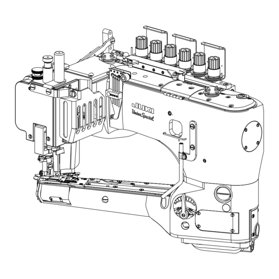
DESCRIPTION OF MACHINES Universal style, Feed-off-the-arm, high speed, medium throw, five or six thread machine. There are four needles and one retainer abreast, one looper and a manually adjusted differential feed control. There is an enclosed automatic lubricating system, filter type oil return pump, visual sight oil action and supply gauges. -
Page 5: L100
LAPSEAMING 36200L100–52/60 4 Needle One Side Trim Lapseamer Fitted with one side fabric trimming lapseam presser foot, edge guide and spreader. Standard: Trimming right side of fabric edge, left side fabric edge trimming can also be done by moving edge guide. For closing the crotch of briefs and panties, sleeves of T-shirts and polo shirts, etc. -
Page 6: Replacement Parts
REPLACEMENT PARTS... -
Page 7: Safety Rules
SAFETY RULES: 1. Before putting the machines described in this manual into service, carefully read the instructions. The starting of each machine is only permitted after taking notice of the instructions and by qualified operators. IMPORTANT! Before putting the machine into service, also read the safety rules and instructions from the motor supplier. -
Page 8: Illustrations
ILLUSTRATIONS This manual has been arranged to simplify ordering repair parts. Exploded views of various sections of the mechanism are shown so that the parts may be seen in their actual position in the machine. On the page opposite the illustration will be found a listing of the parts with their part numbers, description and the number of pieces required in the particular view being shown. -
Page 9: Installation
INSTALLATION Make sure that the Machine is LEVEL when attaching to the installation (table or pedestal), or if machine is moved to a new location. OILING Referring to Fig. 1, fill the machine at (A) and (B). Oil capacity of class 36200 is 2.5 ounces in the bottom reservoir and 2.5 ounces in the top reservoir. -
Page 10: Threading
THREADING FIG. 1... -
Page 11: Adjusting Instructions
ADJUSTING INSTRUCTIONS Instructions stating direction or location, such as right, left, front or rear of the machine are given relative to the operator's position at the machine unless otherwise noted. The handwheel rotates clockwise in operating direction. SETTING THE NEEDLE BAR HEIGHT & ALIGNMENT Insert the first (left) and fourth needles into the needle head. -
Page 12: Setting The Needle Bar Height & Alignment (Cont)
SETTING THE NEEDLE BAR HEIGHT & ALIGNMENT (CONT) Correct spacing of the needles in the throat plate stitch tongue is imperative to proper sewing conditions. Improper relationship of the needles to the stitch tongue often results in malformed stitches. When replacing the stitch tongue make sure needles are aligned properly (see Fig. -
Page 13: Instructions For Using Synchronizing Gauge 21227Cg
SETTING THE LOOPER TRAVEL To adjust the looper travel remove the top front cover and the end cover. Loosen left-handed locknut (A, Fig. 7) and turn screw (B) clockwise to decrease the looper travel or counterclockwise to increase the looper travel. Tighten locknut (A) and recheck setting. NOTE: After setting the looper travel the machine must be checked for synchronization. -
Page 14: Timing The Needles To The Looper (Cont.)
TIMING THE NEEDLES TO THE LOOPER (CONT.) Attach the looper clamp and height gauge (A, Fig. 9) to the heal of the looper by tightening screw (B). Turn the handwheel slowly in a clockwise direction until needle bar (C) touches stop screw (D). Loosen screw (E) and set synchronizing gauge rod (F) so the flat end is on one of the lines in the center of the block (G). -
Page 15: Looper Adjustments
LOOPER ADJUSTMENTS Looper Avoid The looper avoid is set at .094" (2.4mm). Using gauge no. 21227BV (A, Fig. 11), position looper shaft (B) fully to the rear (away from operator) and insert the gauge through the looper shaft hole in the end of the cylinder until the plunger is fully extended from the gauge. -
Page 16: Looper Adjustments (Cont.)
LOOPER ADJUSTMENTS (CONT.) Looper Gauge Turn the handwheel in operating direction until the looper has trav- eled fully to the left. Loosen screw (A, Fig. 15) and move the looper holder to the right or left until the distance from the point of the looper to the center of the first (left) needle is 5/32"... -
Page 17: Setting The Rear Needle Guard
SETTING THE REAR NEEDLE GUARD Set rear needle guard (A, Fig. 18) so it touches the first (left) needle (B) but does not deflect. Check the guard position to the other needles to avoid pinching. Loosen screw (C) and reposition guard (A) as necessary. Tighten screw (C). SETTING THE STITCH LENGTH This machine is designed to sew 10 to 16 stitches per inch. -
Page 18: Setting The Presser Foot (Cont.)
SETTING THE PRESSER FOOT (CONT.) Turn the handwheel in operating direction until link (A, Fig. 20) has traveled fully to the front. There must be a 1/64" (0.4mm) clearance between link (A) and the back of needle bar (B) when link (A) starts to jackknife. -
Page 19: Setting The Presser Foot (Cont.)
SETTING THE PRESSER FOOT (CONT.) The presser foot lifter stop plunger must be set so the cover thread hook will not hit the bottom of the needle head as the presser foot is being lifted. Position the needle bar to its lowest point of travel. -
Page 20: Setting The Knife Drive Lever (Cont.)
SETTING THE KNIFE DRIVE LEVER (CONT.) At this time the knife drive lever should be in the 6 o'clock position. If adjustment is necessary, loosen screws (A, Fig. 28) in the needle lever and reposition knife drive lever (B) to the 6 o'clock position. -
Page 21: Setting The Trimming Knives (All Styles) (Cont.)
SETTING THE TRIMMING KNIVES (ALL STYLES) (CONT.) If necessary loosen screw (A, Fig. 30) and move knife (B) to the right or left as required. Tighten screw (A). If the shear angle between the knives has to be changed, raise or lower screw (C, Fig. 30) in knife holder shank (D). -
Page 22: Looper Thread Adjustment
LOOPER THREAD ADJUSTMENT Loosen screws (A, Fig. 34) and position looper thread cast-off (B) flush with the right end of cast-off support plate (C). Tighten screws (A). Loosen screws (D, Fig. 34 inset) and time take-up (E) so the thread will cast-off when the needle bar has descended 7/64" (2.8mm) from its highest position. -
Page 23: Hung Foot Adjustment
HUNG FOOT ADJUSTMENT When sewing on extremely lightweight material and/or feed cutting is a problem, the presser foot may be "hung" by raising stud (B) until guide (A) rests on the shoulder of stud (B). This adjustment will raise the presser foot slightly, so only the pressure of the presser foot shoes contact the material. -
Page 24: Replacing Presser Foot Shoes
REPLACING PRESSER FOOT SHOES FIG. 39 REMOVING 1. Remove screws (A, Fig. 39). 2. Remove the presser foot shoes (B, Fig. 39) from the presser foot. 3. Remove each shoe (B, Fig. 39) from the shoe holder (C, Fig. 39). RESETTING 1. - Page 25 EXPLODED VIEWS...
-
Page 27: Oil Sight Gauges, Top Covers & Miscellaneous Takeup & Eyelet Parts
OIL SIGHT GAUGES, TOP COVERS & MISCELLANEOUS TAKEUP & EYELET PARTS Amt. Ref. Description Req. Part No. Screw, for crank chamber cover ..............35888N Crank Chamber Cover ................... 22924708 Oil Sight Gauge ..................660-212 "O"Ring ..................... 22516A Screw ......................Screw, for middle top cover ................Screw, for spring ..................... -
Page 29: Main Frame, Bushings & Miscellaneous Eyelet & Cover Parts
MAIN FRAME, BUSHINGS & MISCELLANEOUS EYELET & COVER PARTS Amt. Ref. Description Req. Part No. 36284S Gasket, end cover ..................35887Z End Cover ....................... 22564B Screw, end cover ................... 36290B Main Shaft Bushing, front ................. 92201 Screw, for looper drive lever shaft ..............22829 Screw, looper thread shield ................ -
Page 31: Main Shaft & Miscellaneous Oiling
MAIN SHAFT & MISCELLANEOUS OILING Amt. Ref. Part No. Description Req. 660-207 Oil Seal Ring ....................36294G Oil Reservoir, back ..................36293T Oil Tube Extension ................... 35897BW Gasket ......................29472AG Pump Assembly ....................22585A Screw, for housing cover ................21756G Vent Screw .................... -
Page 33: Crankshaft & Needle Lever Parts
CRANKSHAFT & NEEDLE LEVER PARTS Amt. Ref. Part No. Description Req. 36221N Pulley Assembly ....................22574 Screw ......................61321L Clamp Plate ....................61321J Handwheel ....................36221P Pulley ......................22894E Screw, for pulley ................. 50311C Ball Bearing ....................36293Q Bushing Pump ....................SQ1110401MZ Barb Fitting .................... -
Page 35: Tension Parts
TENSION PARTS Amt. Ref. Part No. Description Req. 36233 Lift Lever Link Connection ................22894J Screw ....................... 36280V Lifter Lever Link Assembly ................22585A Screw ....................... 53678N Washer ..................... 36280U Lifter Lever Link ..................Screw ......................36280A Presser Foot Lifter Stop Plunger ................ 36280C Stop Plunger Segment .................. -
Page 37: Detachable Head, Head Covers, Needle Bar & Needle Bar Head
DETACHABLE HEAD, HEAD COVERS, NEEDLE BAR & NEEDLE BAR HEAD Amt. Ref. Part No. Description Req. 36289B Baffle Plate ...................... 36280J Presser Bar Lifter Lever ..................36294F Oil Deflector Wire .................... 8372A Washer ......................22513 Screw ......................36289H Gasket, for front head cover ................36289 Head Cover, front ................... -
Page 39: Detachable Head, Head Covers, Needle Bar & Needle Bar Head
DETACHABLE HEAD, HEAD COVERS, NEEDLE BAR & NEEDLE BAR HEAD Amt. Ref. Part No. Description Req. 1. thru 33. See Preceding page 36278L Presser Foot Guide, left ................... 36278R Presser Foot Guide, left, for styles 36200L202-50, L202-60 ....... 22653B-8 Screw, for left presser foot guide ..............8372A Washer ........................ -
Page 41: Differential & Main Feed Bars, Feed Dogs & Feed Lift Eccentric Assembly
DIFFERENTIAL & MAIN FEED BARS, FEED DOGS & FEED LIFT ECCENTRIC ASSEMBLY Amt. Ref. Description Req. Part No. 22845M Screw, for differential feed bar driving link ............36236F Differential Feed Bar Driving Link ..............36234N Feed Bar Eccentric Stud .................. 660-220 "O"Ring ..................... -
Page 43: Feed Drive Assembly, Feed Rocker & Looper Avoid Parts
FEED DRIVE ASSEMBLY, FEED ROCKER & LOOPER AVOID PARTS Amt. Ref. Part No. Description Req. 660-207 Oil Seal Ring ....................36236A Feed Rocker Shaft ................... 36237 Differential Feed Adjusting Lever ..............36237A Differential Feed Adjusting Link ............... 22504C Screw ......................36236J Differential Driving Link Stud ................ -
Page 45: Knife Driving Parts
KNIFE DRIVING PARTS Amt. Ref. Part No. Description Req. 36251B Cover Thread Carrier and Hook Driving Sleeve ........12934A Nut ......................51235G Washer ....................36245K Screw ..................... 36245H Rod End Bearing ..................36245D Nut, right thread ..................36251AE Cover Thread Carrier and Hook Driving Connection Rod Ball Joint ..36275A Washer .................... -
Page 47: Looper Rocker Shaft & Looper Rocker Drive Parts
LOOPER ROCKER SHAFT & LOOPER ROCKER DRIVE PARTS Amt. Ref. Description Req. Part No. 36210 Looper Mounted Needle Guard, marked “FZ” ..........Screw, for needle guard ................. 36208A Looper ......................22585A Screw ......................36248 Looper Holder ....................1096B Looper Adjusting Screw ................22564D Screw ....................... -
Page 49: Lap Former, Miscellaneous Cylinder Covers, Throat Plate, & Chain Cutting Knife
LAP FORMER, MISCELLANEOUS CYLINDER COVERS, THROAT PLATE, & CHAIN CUTTING KNIFE Amt. Ref. Description Req. Part No. 36224H Throat Plate, for Style 36200L210-52 ..............36224K Throat Plate, for Style 36200L210-60 ..............36240 Stitch Tongue, marked “D”, for Throat Plates 36224H ........ 36240J Stitch Tongue, marked “AC”, for Throat Plates 36224K ...... -
Page 51: Cylinder Bushings, Differential Feed Control Assembly & Miscellaneous Cylinder Covers
CYLINDER BUSHINGS, DIFFERENTIAL FEED CONTROL ASSEMBLY & MISCELLANEOUS CYLINDER COVERS Amt. Ref. Part No. Description Req. 36284R Gasket, for front cylinder cover and oil gauge ..........36284C Cylinder Cover and Oil Gauge, front .............. J87J Screw, for front cylinder cover and oil gauge ..........36249A Bushing, for looper shaft, front ................ -
Page 53: Presser Foot For Styles 36200L200-52, L200-60, L201-60, L210-52, L210-60, U300-52, U300-60
PRESSER FOOT FOR STYLES 36200L200-52, L200-60, L201-60, L210-52, L210-60, U300-52, U300-60 Amt. Ref. Part No. Description Req. 36220E Presser Foot, complete, for Style 36200L200-52, U300-52 ........ 36220H Presser Foot, complete, for Style 36200L210-52 ..........36220M Presser Foot, complete, for Style 36200L210-60 ..........36220V Presser Foot, complete, for Style 36200L201-60 .......... -
Page 55: Presser Foot For Styles 36200L100-52, L100-60, T300-52, T300-60, U300-52, U300-60
PRESSER FOOT FOR STYLES 36200L100-52, L100-60, T300-52, T300-60, U300-52, U300-60 Amt. Ref. Part No. Description Req. 36220A Presser Foot, complete, for Styles 36200L100-52, U300-52 ......36220K Presser Foot, complete, for Styles 36200L100-60, U300-60 ......22731 Screw, for chip guard ................36279D Spring, for chip guard ................ -
Page 57: Presser Foot For Styles 36200L202-52, L202-60
PRESSER FOOT FOR STYLES 36200L202-52, L202-60 Amt. Ref. Part No. Description Req. 36220AE Presser Foot, complete, for Style 36200L202-52 ..........36220AF Presser Foot, complete, for Style 36200L202-60 ..........22-331 Pin ......................36251K Link Pin, for 5, 6 and 8 ................. 22738P Screw ...................... -
Page 58: Presser Foot Shoe Chart
PRESSER FOOT SHOE CHART 1) THICKNESS OF SHOES— THICK: approximately .020" (0.5mm) thick, for medium to heavy weight materials that require heavy presser foot pressure. THIN: approximately .014" (0.35mm) thick, for light to medium weight materials, that require light presser foot pressure and when marking of the material by the shoes and/or feed dogs is a problem. -
Page 59: Presser Foot Shoe Chart
PRESSER FOOT SHOE CHART 0 . 5 0 . 5 MM MM Thickness Thickness 0 . 35 35 MM MM Thickness Thickness One-sideTrim 4 MM 2 . 4 2 . 4 MM 4 . 8 4 . 8 MM 4 . 8 4 . -
Page 61: Thread Stand
THREAD STAND Amt. Ref. Part No. Description Req. 21101W6 Thread Stand, complete ................. 21233KS Bracket Connection, marked “KS” ..............22651CD-5 Screw, for bracket connection ..............28604R Oil ........................* These parts used with pedestal. -
Page 63: Miscellaneous Gauges & Tape Reel Parts
MISCELLANEOUS GAUGES & TAPE REEL PARTS Amt. Ref. Part No. Description Req. 21227CN Looper Travel Gauge, complete ..............21227CM Looper Travel Gauge Pointer ..............21227CS Looper Travel Gauge Plate ............... 21388AZ Wrench, for driving link stud ................21227BU Needle Height Gauge, for all Styles except 36200L100-60, L202-60, L210-60 21227DS Needle Height Gauge, for Styles 36200L100-60, L202-60, L210-60 .... -
Page 65: Thread Lubricator
THREAD LUBRICATOR Amt. Ref. Part No. Description Req. 29480AZY Needle Thread Lubricator Complete .............. 35893J Reservoir Cover ..................666-339 Reservoir Wick ..................22585C Screw ....................... 660-219AX Pin ......................50358M Eyelet ....................... 22894BL Shoulder Screw ..................35893K Reservoir ....................28604W Bottle of Silicone (not shown) .............. -
Page 66: Numerical Index Of Parts
NUMERICAL INDEX OF PARTS Part No. Page No. Part No. Page No. Part No. Page No. Part No. Page No. Part No. Page No. 35846 ....43 36223 ....31 109 ....35 22849 ..49, 51 22571A .....49 35846B .....43 36223A .....31 1096 ..31, 53 22881A .....37 22571B .....31 35850F .....51... -
Page 67: Numerical Index Of Parts
NUMERICAL INDEX OF PARTS Part No. Page No. Part No. Page No. Part No. Page No. Part No. Page No. Part No. Page No. 36280T .....35 36297J .....31 36237L .....51 36260C .....29 6 6 0 - 9 3 5 ... 2 7 36280U .....35 36297N .....31 36237M .....39...