Table of Contents
Advertisement
INSTALLATION MANUAL
• Please read this installation manual completely before installing the product.
• Installation work must be performed in accordance with the national wiring
standards and local code by authorized personnel only.
• Please retain this installation manual for future reference after reading it
thoroughly.
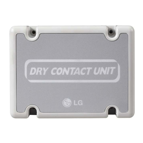
TYPE : Dry contact Module for thermostat
MODELS
PQDSBNGCM1
P/NO : MFL42540217
www.lg.com
Advertisement
Table of Contents

Summary of Contents for LG V-Net PQDSBNGCM1
- Page 1 • Installation work must be performed in accordance with the national wiring standards and local code by authorized personnel only. • Please retain this installation manual for future reference after reading it thoroughly. TYPE : Dry contact Module for thermostat MODELS PQDSBNGCM1 www.lg.com P/NO : MFL42540217...
-
Page 2: Table Of Contents
Dry contact Module for thermostat Ownerʼs &installation manual TABLE OF CONTENTS Safety Precautions ............. 3~4 Name of each part ..............5 Installation Method ............. 6~7 Installation inside of the indoor unit............6 Installation outside of the indoor unit ............7 Setting and using method ..........8~14 1. -
Page 3: Safety Precautions
Safety Precautions Safety Precautions To prevent injury to the user or other people and property damage, the following instructions must be followed. Incorrect operation due to ignoring instruction will cause harm or damage. The seriousness is WARNING This symbol indicates the possibility of death or serious injury. CAUTION This symbol indicates the possibility of injury or damage. - Page 4 Safety Precautions WARNING During use Do not modify or extend the Do not use any heating power cord. devices near the product. devices near the power cord. • It can cause electric shock, • • It can cause electric shock, It can cause electric shock, explosion, injury and problems explosion, injury and problems...
-
Page 5: Name Of Each Part
Name of each part Name of each part (Rear case) (Front case) (Top) (Internal PCB board) (Side) (Side) DRY CONTACT FOR COMMUNICATION ( DRY_CONTACT FOR THERMOSTAT) 1. CN_INDOOR : Connector for indoor unit 2. CHANGE_OVER_SW : Switch to select External Voltage or Non Voltage for input contact signal 3. -
Page 6: Installation Method
Installation Method Installation Method Installation inside of the indoor unit ① Loosen 4 screws anchoring PCB and then separate PCB from the rear case ② Connect the connection wires according to the instructions. (Please refer to Setting and Using Method beginning on page 8) ③... -
Page 7: Installation Outside Of The Indoor Unit
Installation Method Installation outside of the indoor unit ① Screw the rear case on the installation surface using screws. ② Please cut the tab which is located in side of the front case properly. ③ Connect connection wires according to the instructions. -
Page 8: Setting And Using Method
Setting and using method Setting and using method After change any Dry contact setting, then you must press RESET switch to reflect the setting. 1. Power supply and indoor unit connection n When using the Dry contact for communication independently CN_Ther/Oper CN_Mode CN_WIND... -
Page 9: Setting Of Contact Signal Input
Setting and using method 2. Setting of Contact Signal Input For no power contact point signal input Thermostat LG does not supply this section (Field supply) CHANGE OVER_SW CN_Ther/Oper CN_Mode CN_WIND CHANGEOVERSW RESET_SW STEETING_SW WARNING DISPLAY_LED Notes TEMP_SW Do not input the voltage signal in CN_OUT "NON VOLT"... -
Page 10: Setting Of ʻSetting_Swʼ
Setting and using method 3. Setting of ʻSETTING_SWʼ n Using ʻSETTING_SWʼ , select the Option of control Function as described below CN_Ther/Oper CN_Mode CN_WIND CHANGEOVERSW RESET_SW STEETING_SW DISPLAY_LED TEMP_SW STEETING_SW CN_OUT <SETTING_SW Function> WIND Signal Thermal Oper Mode Dry Contact Control en/disable en/disable en/disable... - Page 11 Setting and using method Flow Chart for SETTING_SW -. When not using WIND signal Use WIND Signal? Set the switch ‘0 ~ 7’ Use Thermal function? Set the switch ‘0 ~ 3’ Set the switch ‘4 ~ 7’ Use Operation mode? Use Operation mode? Set the switch ‘0 ~ 1’...
- Page 12 Setting and using method n Function table for the selection of ʻSETTING_SWʼ and the input signal CN_Ther/Oper CN_Mode CN_WIND CHANGEOVERSW SETTING_SW RESET_SW CN_MODE input SETTING Function HEAT COOL COOL HEAT 2,3,6,7,A,B,E,F Others CN_WIND input Function SETTING Middle High High Middle 8,9,A,B,C,D,E,F Others CN_Ther/Oper input...
-
Page 13: Setting Of ʻTemp_Swʼ
Setting and using method 4. Setting of ʻTEMP_SWʼ ■ When setting the desired temperature of the Dry contact Module : When operating the indoor unit using Dry contact moduleʼs desired temperature, set the desired temperature according to the ʻTEMP_SWʼ setting. If Thermostat priority control mode is disabled , the desired temperature can be reset by other controller - Use the ʻTEMP_SWʼ... -
Page 14: Indoor Unit Monitoring
Setting and using method 5. Indoor unit monitoring n Monitoring whether the indoor unit is operating: Refer to below and connect to the control device that you want to control. CN_Ther/Oper CN_Mode CN_WIND CHANGEOVERSW RESET_SW STEETING_SW DISPLAY_LED TEMP_SW CN_OUT Field Supply Power Operation Display AC or DC...


