
Related Manuals for RocketFish RF-HTLF23


Summary of Contents for RocketFish RF-HTLF23
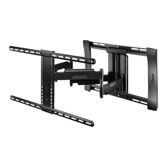
- Page 1 40" to 75" TV WALL MOUNT - FULL MOTION RF-HTLF23 ASSEMBLY GUIDE Before using your new product, please read these instructions to prevent any damage.
-
Page 2: Table Of Contents
LIFETIME LIMITED WARRANTY ..........26 Introduction Congratulations on your purchase of a high-quality Rocketfish product. Your RF-HTLF23 represents the state of the art in TV wall-mount design and is designed for reliable and trouble-free performance. IMPORTANT SAFETY INSTRUCTIONS SAVE THESE INSTRUCTIONS •... -
Page 3: Specifications
RF-HTLF23 Specifications • Maximum TV weight: 100 lbs. (45.3 kg) • Screen size: From 40 in. to 75 in. (101.6 cm to 190.5 cm) diagonal • Overall dimensions (H × W): 17.7 × 25.1 in. (45 cm × 63.9 cm) •... -
Page 4: Tools Needed
Tools needed You need the following tools to assemble your new TV wall mount: Level Measuring tape Pencil Drill Phillips screwdriver Socket wrench with 1/2" (13 mm) socket or adjustable wrench Tape Wood Stud Wall Concrete or Concrete Block Wall Hammer 3/8"... -
Page 5: Package Contents
RF-HTLF23 Package contents Make sure that you have all the hardware necessary to assemble your new TV wall mount: 04 Horizontal bracket (2) 07 Template (1) 05 Vertical bracket (1) 08 Wall plate (1) 11 Arm assembly (1) Need help? Call 1-800-620-2790 (U.S. and Canada) -
Page 6: Tv Hardware
TV Hardware Lbl. Hardware Lbl. Hardware M6 × 12 mm screw Spacer (2.5 mm) M6 × 35 mm screw Spacer (22 mm) M5 × 10 mm TV M8 × 16 mm interface screw screw M8 × 25 mm Lag screw 5/16 × 2 3/4 in. screw Washer 5/16 in. -
Page 7: Installation Instructions
RF-HTLF23 Concrete Installation Kit CMK1 (not included) Contact customer service at 1-800-359-5520 to have these additional parts shipped directly to you. Lbl. Hardware Lag screw 5/16 × 2 3/4 in. Washer 5/16 in. Concrete anchors (Fischer UX10 x 60R) Installation instructions... - Page 8 • Obstructed back: The brackets block any of the jacks on the back of your TV. You need 2.5 mm or 22 mm spacers ( 3) when assembling the wall mount. • Irregularly-shaped back: There is a gap between the brackets and some part of the back of your TV.
- Page 9 RF-HTLF23 STEP 2 - Select screws, washers, and spacers Select the hardware for your TV (screws, washers, and spacers). A limited number of TVs come with mounting hardware included. (If screws came with your TV, they are almost always in the holes on the back of your TV.) If you don't know the correct length of the mounting screws your TV requires, test various sizes by hand threading the screws.
- Page 10 STEP 3 - Option 1: Attaching the horizontal brackets to a TV with a flat back CAUTION: To avoid personal injury or property damage, do not use power tools. Align the holes you noted on the horizontal brackets (04) with the screw holes on the back of your TV.
- Page 11 RF-HTLF23 STEP 3 - Option 2: Attaching the horizontal brackets to a TV with irregular or obstructed back CAUTION: To avoid personal injury or property damage, do not use power tools. Place the spacers you selected in STEP 2 ( ) over the screw holes on the back of your TV.
- Page 12 STEP 4 - Attaching the vertical bracket CAUTION: To avoid personal injury or property damage, do not use power tools. Lay the vertical bracket ( ) on top of the horizontal brackets (04). Make sure that the bracket is centered. Secure the vertical bracket to the horizontal brackets with the TV interface screws ( ).
- Page 13 RF-HTLF23 STEP 5 - Determine wall-mount location Note: Your TV should be high enough so your eyes are level with the middle of the screen from a seated position (normally, 40 to 60 inches from the ground). For more detailed information on determining where to drill your holes, visit our online height-finder at: http://mf1.bestbuy.selectionassistant.com/index.php/heightfinder...
- Page 14 STEP 6 - Option 1: Installing on a wood stud wall Note: Drywall covering the wall must not exceed 5/8" (16 mm). Locate the stud, then verify the center of the stud with an edge-to-edge stud finder. Make sure that the distance between the studs is 16 in. (40.6 cm). Note: Drywall covering the wall must 16"...
- Page 15 RF-HTLF23 Align the center of the wall plate template (07) at the height you determined in the previous step and make sure that it is level. Tape the template to the wall. 2 3/4 in (69 mm) 7/32 in (5.5 mm) Drill four pilot holes through the template to a depth of 2 3/4 in.
- Page 16 Align the wall plate ( ) with the pilot holes, insert the lag screws ( ) through washers ( ) and into the holes in the wall plate, then tighten the lag screws only until they are firm against the wall plate assembly. CAUTION: Avoid potential injuries or property damage! DO NOT over-tighten the lag screws (09).
- Page 17 RF-HTLF23 STEP 6 - Option 2: Installing on a solid concrete or concrete block wall CAUTION: To prevent property damage or personal injury, never drill into the mortar between the blocks. Mount the wall plate directly onto the concrete surface.
- Page 18 Drill pilot holes to a depth of 3 in. (7.6 cm) using a 3/8 in. (10 mm) diameter masonry drill bit, then remove the template. 3 in. (76 mm) Insert the concrete wall anchors ( ) (see Concrete Installation Kit CMK1 (not included) on page 7) into the pilot holes and use a hammer to make sure that the anchors are flush with the concrete surface.
- Page 19 RF-HTLF23 Align the wall plate ( ) with the anchors, insert the lag screws ( ) through the washers ( ) and into the holes in the wall plate assembly, then tighten the lag screws only until they are firm against the wall plate.
- Page 20 STEP 7 - Attach the arm assembly to the wall plate Hang the arm ( ) onto the wall plate ( ) by first hooking the top of the arm assembly into the wall plate channel, then lowering the bottom of the assembly into place.
- Page 21 RF-HTLF23 Use the hex key ( ) to secure the arm assembly to the wall plate ( ) with the wall plate screws ( CAUTION: These wall plate screws must be installed to secure your TV onto the wall plate assembly.
- Page 22 STEP 8 - Attach your TV to the arm assembly Hang your TV onto the arm assembly ( ) by first hooking the top support of the vertical bracket ( ) onto the assembly, then resting your TV into place. You hear an audible click when your TV is in place.
- Page 23 RF-HTLF23 Use the hex key ( ) to lock your TV to the arm assembly with the locking screw ( IMPORTANT: The locking screw must be installed to secure your TV onto the arm assembly. HEAVY! You may need assistance with this step.
- Page 24 STEP 9 - Managing cables • Fully extend the arm assembly ( ) to provide enough slack, then routing cables along the arms and inserting them into the channels on the arms to provide a clean look to your installation. STEP 10 - Adjust tilt Note: After your TV is in place, tighten the tilt tension knob to prevent unwanted movement.
- Page 25 RF-HTLF23 STEP 10 - Adjust the level Loosen the locking screw ( Turn the leveling screw ( ) with a Phillips screwdriver to level your TV. Retighten the screw ( Removing your TV from the wall mount Disconnect all cables, then pull down the release cord located below the vertical bracket to unlock your TV from the vertical bracket.
-
Page 26: Lifetime Limited Warranty
Products and parts replaced under this warranty become the property of Rocketfish and are not returned to you. If service of Products or parts are required after the Warranty Period expires, you must pay all labor and parts charges. This warranty lasts as long as you own your Rocketfish Product during the Warranty Period. - Page 27 FOR THE BREACH OF ANY EXPRESS OR IMPLIED WARRANTY ON THIS PRODUCT, INCLUDING, BUT NOT LIMITED TO, LOST DATA, LOSS OF USE OF YOUR PRODUCT, LOST BUSINESS OR LOST PROFITS. ROCKETFISH PRODUCTS MAKES NO OTHER EXPRESS WARRANTIES WITH RESPECT TO THE PRODUCT, ALL EXPRESS AND...
- Page 28 Part # 6907-302025 www.rocketfishproducts.com 1-800-620-2790 (U.S. and Canada) ROCKETFISH is a trademark of Best Buy and its affiliated companies. Registered in some countries. Distributed by Best Buy Purchasing, LLC 7601 Penn Ave South, Richfield, MN 55423 U.S.A. ©2019 Best Buy. All rights reserved.