Siemens NK8000 Series Installation, Configuration & Operation
Hide thumbs
Also See for NK8000 Series:
- Installation, function & configuration (70 pages) ,
- Application & planning (96 pages)

Related Manuals for Siemens NK8000 Series


Summary of Contents for Siemens NK8000 Series
- Page 1 NK8000 MP4.81-02 NK8222, NK8223, NK8225 NK8231, NK8232, NK8235 Installation Configuration Commissioning Building Technologies A6V10062437_a_en 30.01.2019 CPS Fire Safety...
-
Page 3: Table Of Contents
Table of contents About this document ......................5 Security disclaimer ......................8 Safety regulations ......................9 Country-specific standards ....................9 Assembly and installation ....................9 Commissioning and testing....................9 Disposal and recycling ....................... 10 Modifications to the system design and the products ............10 Data privacy and protection .................... - Page 4 5.1.1 NE8001 hardware requirements ............33 5.1.2 NE8001 hardware installation ............. 34 NK822x hardware installation ................36 NK823x hardware installation ................42 Software installation ..................48 Installation checklist .................... 48 Composer tool ....................48 Launching Composer ..................49 NW8202 IP configuration download tool ............50 6.4.1 NW8202 hardware requirements ............
-
Page 5: About This Document
Training program information including the Siemens intranet link ⚫ A complete list of all available DMS8000 documents ⚫ Instructions for how to obtain a document via the Siemens intranet using the ⚫ Siemens Asset Portal A map of relevant documents for each target audience group ⚫... - Page 6 4. In the list, select one or more documents and click the Download Assets icon. 5. After the download preparation completes (Background Process …), click Download and follow the instructions of your browser. For more information such as Siemens news and announcements, visit the STEP Web portal at: https://workspace.sbt.siemens.com/content/00001123/default.aspx Note: Before beginning work on the system you must have read and understood the Safety Regulations [➙...
- Page 7 For more information on creating flowcharts, printed material are indicated with an arrow see Flowcharts [→92]. and the page number, enclosed in brackets: [→92] Modification index Note: For versions more than four years old, please visit the Siemens Asset Portal. Version Date Notes A6V10062437_a_en 01.2019 NK8000 MP4.81-02 service release.
-
Page 8: Security Disclaimer
Security disclaimer Security disclaimer Products, solutions and services from Siemens include security functions to ensure the secure operation of building automation and control, fire safety, security management, and physical security systems. The security functions on these products, solutions and services are important components of a comprehensive security concept. -
Page 9: Safety Regulations
Country-specific standards Siemens Building Technologies products are developed and produced in compliance with the relevant international and European safety standards. This document provides warnings and recommendations specific to NK8000 products. -
Page 10: Disposal And Recycling
Modifications to the system design and the products Note: Modifications to a system or to individual products may cause faults or malfunctioning. Please request written approval from Siemens Building Technologies and from any relevant authorities concerning intended system modifications and system extensions. Data privacy and protection Make sure that the configuration of the system complies with local data privacy and protection regulations. -
Page 11: Introduction
Introduction Interactions 1 Introduction The NK8000 family provides LAN/WAN adapter products for a safety and security network: NK822x series (no longer available, end of service: 31 December 2015) ⚫ NK823x Ethernet Ports series (NK8231, NK8232, NK8235) ⚫ NK8237 Modbus Gateway ⚫... -
Page 12: Interactions
Introduction Interactions Interactions The unit can be programmed to support interactions between the connected subsystems: when a specified message is received from a source subsystem, one or more commands are generated for a destination subsystem according to the programmed interaction logic. local network-wide Interactions can be... -
Page 13: What's New
Introduction What's new What's new Here is the list of modifications for new functions and software improvements. NK8000 MP4.81-02 Service Release Section Modifications 6.4 NK823x Web Server Removed support of NK823x Web Server 7.2 Configuring IP settings via the NK823x Web Removed support of NK823x Web Server Server 9.4 NK823x Web Server... -
Page 14: System Limits
System limits NS8210 driver system limits 2 System limits The following describes the system limits for the NK82xx units and the corresponding NS82xx drivers for DMS8000 (MM8000 and MK8000) systems. For NK8000 detailed information about supported subsystem software versions see the Release Notes (document n.A6V10062453.) NS8210 driver system limits... -
Page 15: Nk822X System Limits
System limits NK822x system limits NK822x system limits Network capabilities (upstream towards management system host) Ethernet IEEE 802.3, 10Base-T, half-duplex, no auto-sensing or auto- ⚫ negotiation Single host transport protocols: ⚫ – CEI 79-5 type A and B (optional FEAL 64-bit encryption) –... -
Page 16: Nk823X System Limits
System limits NK823x system limits NK823x system limits Network capabilities (upstream towards management system host) 2 Ethernet interfaces IEEE 802.3, 10/100 Base-T with auto-negotiation, ⚫ half/full-duplex with auto-sensing, auto-crossover (thus eliminating the need for crossover cables) Single host transport protocols: ⚫... - Page 17 System limits NK823x system limits control actions). Interactions are only possible between locally connected subsystems. For supported subsystems see Interactions [➙ 12] ⚫ Logical combinations: AND, OR, XOR, NOT ⚫ Delay of effects (wait): configurable 0…6500 sec ⚫ Max # of typical interactions (1-6 triggers, 1-4 effects): 500 ⚫...
-
Page 18: Structure And Functions
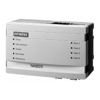
Structure and functions NK822x hardware 3 Structure and functions NK822x hardware The NK822x is composed of an electronic board (with optional plug-ins) installed in a compact and robust plastic box. NK822x Ethernet port (NK8223 in this example) 3.1.1 Front panel The front panel houses 9 LED’s. -
Page 19: Internal Dip Switches
Structure and functions NK822x hardware Blinking (4 flashes) : trouble with the serial/network interface. ⚫ Blinking (5 flashes) : trouble with DLL or RCLOCK file(s). ⚫ : critical/hardware fault. ⚫ Right Side LEDs The four LEDs on the right side are from top to bottom: Name Function Com1... -
Page 20: Serial Interfaces
Structure and functions NK822x hardware NK822x internal DIP switch and jumpers Item Description DIP-Switches Reset button JP6: enable LON resistor. Tamper switch JP3: disable tamper or connect to external tamper. 3.1.4 Serial interfaces NK8223 / NK8225: although the maximum number of serial lines is 4, they are not always used. -
Page 21: Lon Interface
Structure and functions NK822x hardware 3.1.5 LON interface 3.1.5.1 PC/104 LON adapter The NK822x processor board is equipped with a standard PC/104 interface for system expansion. This is used for the LON add-on board. Note: There are two revisions of LON interface boards, which have different LED indications and different rotary switch settings. -
Page 22: Ethernet Interface
Structure and functions NK822x hardware Subnet Node CD00251 Rev.A boards CD00251 Rev.B boards Default LON address settings for communications with Guarto MP3 on NK22xx rotary switches LON address assignment for CS6 Guarto MP3 The LON communication between NK822x and CS6 Guarto is based on logical BACnet addresses for both devices. -
Page 23: I2C Interface: I/O And Power Supervision
Structure and functions NK822x hardware 3.1.7 I2C interface: I/O and power supervision This interface allows for a direct support of: Direct digital input/output: ⚫ – One or two DF8040 (CF9040) input modules – One DF8020 (CF9020) output module Power supply supervision: ⚫... -
Page 24: Nk823X Hardware
Structure and functions NK823x hardware For more information about the DF8000 Input/Output modules, including DF8000 Datasheet (document installation details, see documents no.A6V10081184) DF8000 ICC (document no.A6V10081388) NK823x hardware The NK823x is composed of an electronic board (with optional plug-ins) installed in a compact and robust plastic box. -
Page 25: Internal Dip Switches
Structure and functions NK823x hardware : critical/hardware fault. ⚫ Diagnostics (yellow LED) Internal interface diagnostics: : status OK. ⚫ Blinking (fast) : booting operating system after restart. ⚫ Blinking (1 flash) : missing or insufficient license. ⚫ Blinking (2 flashes) : trouble with the I C bus to I/O modules. -
Page 26: Internal Jumpers
Structure and functions NK823x hardware 3.2.3 Internal jumpers X101 X102 X103 X104 X105 X111 Internal DIP switch and jumpers (NKM8001-A1 mainboard) Item Name Description S101 DIP-Switches Reset button Tamper switch X115 When closed, it disables the box tamper alarm. Building Technologies A6V10062437_a_en CPS Fire Safety 30.01.2019... -
Page 27: Serial Interfaces
Structure and functions NK823x hardware X101 X102 X103 X104 X105 X111 Internal DIP switch and jumpers (NKM8001-A2 mainboard) Item Name Description S101 DIP-Switches Reset button Tamper switch X115 When closed, it disables the box tamper alarm. 3.2.4 Serial interfaces NK8231.2 NK8232.2 NK8235.2 : these models are equipped with two serial... -
Page 28: Onboard I/O
Structure and functions NK823x hardware 3.2.6 Onboard I/O The NK823x main board is equipped with three digital inputs (X102) and one relay output (X101). The input signals can be used individually or combined together for power supply supervision application. X102 onboard inputs. Signal Circuit 1 Circuit 2... - Page 29 Structure and functions NK823x hardware DF8046 DF8046 is a module providing 4 supervised inputs (normally-open balanced inputs) designed for migration of CS100/DMS7000 Multiplexer systems with B1G030 line supervision boards. See NK823x hardware installation [➙ 42] for more information on the connection of I/O modules to the NK823x.
-
Page 30: Ethernet Interfaces
Structure and functions NK823x hardware 3.2.8 Ethernet interfaces The NK823x main board is equipped with two Ethernet interfaces. The two RJ-45 connectors also include 2 LEDs (yellow and green) reporting the LAN status as follows: Yellow LED: if on, a 100 Mbps link is active. ⚫... -
Page 31: Sd Card
Structure and functions NK823x hardware 3.2.10 SD card The NK823x mainboard is equipped with a 16 GB SD card. The SD card slot is located below the CPU module and can be accessed only by removing the plastic housing. The SD card can be used to log data about network communications (see Network Connectivity Guide , document no.A6V10359485). -
Page 32: Nk8000 Security
NK8000 Security 4 NK8000 Security To ensure the system security and prevent physical damages and attacks that may compromise the system integrity and confidentiality, make sure to install NK823x units according to the following criteria: NK823x units must be updated to latest Kernel and firmware versions. ⚫... -
Page 33: Hardware Installation
Hardware installation NE8001 housing solution for NK823x 5 Hardware installation There are various possible installation scenarios. Namely: Installation of NK82xx in existing cabinets. ⚫ a. DIN-rail mounting (typical) in plastic housing. b. Mounting of the NK823x board in the control unit housing using card holders and the NE8001 mounting kit. -
Page 34: Ne8001 Hardware Installation
Hardware installation NE8001 housing solution for NK823x 5.1.2 NE8001 hardware installation The cabinet is typically wall-mounted. A proper support must be provided for the maximum weight (see Technical data on the NK8000 datasheet). Four supporting screws or hooks (min. 10 mm) are required. WARNING Supporting wall must not be composed of inflammable material. - Page 35 Hardware installation NE8001 housing solution for NK823x arrow ) where they should be anchored securely before being connected to the screw terminators. 20 mm hole cut-outs Top view of NE8001 cabinet WARNING When entering the metallic frame of the cabinet, wires should be protected by a self-extinguishing plastic cord guard (UL94-V2 flammability rating).
-
Page 36: Nk822X Hardware Installation
Hardware installation NK822x hardware installation Wiring (2) – Entrance hole indicated by arrow 5.1.2.1 NK8021 modem mounting in an NE8000 cabinet 1. Screw in the modem holder brackets using the holes provided in the back of the cabinet. 2. Slide the modem plate into the brackets. 3. - Page 37 Hardware installation NK822x hardware installation 3. If used, set appropriate I2C addresses for I/O modules: – Input modules (DF8040) have addresses 1 or 2 – Output module (DF8020) has address 1 – Power supply supervision module (DF8090), factory set to address 8. 4.
- Page 38 Hardware installation NK822x hardware installation Bottom view Serial RS232 interfaces Item Name Description COM 3 — COM 4 — COM 1 In place of CN4 COM 2 — Note: NK8222 and some NK8223/NK8225 configurations do not include COM3/COM4. Building Technologies A6V10062437_a_en CPS Fire Safety 30.01.2019...
- Page 39 Hardware installation NK822x hardware installation Power connections Power supply RS485-1 POWER SUPPLY DF8090 BATTERY 27Ah 12V Batt Vin = Voltage In Vout Vout = Voltage Out Batt = Battery NK822x power connections CN1: Ethernet connector A standard RJ45 connector connects Ethernet. Category 5 or 6 UTP cabling is best suited.
- Page 40 Hardware installation NK822x hardware installation CN3: Power supply Power connections. Assignment + PWR Earth – PWR — — CN4 (NK822x) / X104 and X105 (NK823x): RS485 connectors RS485 connectors. Assignment + RS485 – RS485 COM 1 ... COM 4: RS232 connectors RS232 lines are connected to 9pin D-Sub connectors, female type.
- Page 41 The I/O modules are mounted the same way. Note: Before removing the box, carefully disconnect the flat cable (bus) of the I module, as well as the power supply cables. C interface SIEMENS Power Com 1 Vital functions Com 2...
-
Page 42: Nk823X Hardware Installation
Hardware installation NK823x hardware installation Installation in subsystem housing without DIN-rail NK822x can be installed without the plastic box using the specific mounting kit for CS11/CS440. NK822x mounting option for CS11 AlgoRex CS11 EP7F Planning Note: For more details, see document no. 008725 ( NK823x hardware installation Installation 1. - Page 43 Hardware installation NK823x hardware installation Top view 321 654321 87654321 21 21 NK823x electrical interfaces (top view) Item Name Description Ethernet 2 Ethernet 1 X101 1 output X102 3 inputs X103 Power supply X104 RS485 (in place of COM1) X105 RS485 (in place of COM2) Bottom view Serial RS232 interfaces (bottom view)
- Page 44 Hardware installation NK823x hardware installation Note: COM 3 / COM 4 is only available on NK8235.4. Power connections Note the dual power supply input for redundant solutions. X103 X104 X105 Power supply RS485-1 RS485-2 POWER SUPPLY DF8090 BATTERY 27Ah 12V Batt Vin = Voltage In Vout...
- Page 45 Hardware installation NK823x hardware installation Earth – Not used Not used Secondary (optional) Earth – X2/X3: Ethernet Connector A standard RJ45 connector connects Ethernet. Category 5 or 6 UTP cabling is best suited. Ethernet connections. Assignment TX– n.c. n.c. RX– n.c.
- Page 46 The I/O modules are mounted the same way. Note: Before removing the box, carefully disconnect the flat cable (bus) of the I module, as well as the power supply cables. C interface SIEMENS Power Com 1 Vital functions Com 2...
- Page 47 Hardware installation NK823x hardware installation NKA8011-A1 mounting plate Building Technologies A6V10062437_a_en CPS Fire Safety 30.01.2019...
-
Page 48: Software Installation
Software installation Installation checklist 6 Software installation The software installation includes the following: Composer and basic tools for system configuration. ⚫ Additional tools: NW8202 (for IP configuration download), NW8204 (for ⚫ maintenance and diagnostic). Installation checklist Items needed for the installation The DMS8000 DVD ⚫... -
Page 49: Launching Composer
Software installation Launching Composer Launching Composer Do one of the following: ⚫ – Launch Composer through the Start menu: Start > Programs > DMS8000 > Composer. – Launch Composer by selecting the shortcut icon on your desktop, if available. When you start Composer for the first time, the following window displays: Composer server selection Note: To see this window every time you start Composer, deselect the Hide this dialog check box. -
Page 50: Nw8202 Ip Configuration Download Tool
Software installation NW8202 IP configuration download tool After you make your server selection, and for all subsequent times when you start Composer, the Projects Management window displays: Projects Management window The Project Market Package version is indicated in parentheses. Note 1: To access the Projects Management window from an open project, select Tools >... -
Page 51: Nw8202 Installation
Software installation NW8204 diagnostic tool 6.4.3 NW8202 installation You can install the NW8202 tool when you install the DMS8000 system. You can also install it separately on a different PC (such as a service PC) at a later time. On a DMS8000 system, you launch NW8202 by selecting the NW8202.exe file from the following directory: <InstallationDir>... - Page 52 Software installation NW8204 diagnostic tool On a DMS8000 system, you launch NW8204 by selecting the NW8204.exe file from the following directory: <InstallationDir>\Communication Layer\NK8210WebServer\NW8204 The default installation folder is: C:\Program files\DMS8000 (assuming an English version of Windows). To install the NW8204 tool on a service PC, do the following: 1.
-
Page 53: Secure Communication For Web Services
Internet websites. Several certificate authorities can provide an SSL certificate for a moderate annual charge (in case of issues, contact your local IT manager or the Siemens customer support center). Configure the browser of your client systems to trust the self-signed certificate. -
Page 54: Configuration
Configuration Configuration checklist 7 Configuration After you have installed the DMS8000 and Composer software, you must configure Installation Function & the DMS8000 system (follow the product-specific Configuration Commissioning Guide Once that is done, you perform the configuration procedures to get the NK8000 units communicating with the DMS8000 system. -
Page 55: Configuring Ip Settings Via Nw8202
Configuration Configuring IP settings via NW8202 Configuring IP settings via NW8202 This configuration must be performed before the NK8000 can be configured at the client’s site. This procedure details how to send the IP configuration information; that is, the IP address, Subnet mask, and Default address to the NK8000 via the NW8202 Tool. - Page 56 Configuration Configuring IP settings via NW8202 7. Click Download. The Download Procedure window is displayed. 8. Follow the instructions displayed. Note: On the NK823x unit, connect the network cable on Ethernet port 1. Note: Note the different DIP switch depending on the NK82xx model: set DIP switch n.2 for NK822x and DIP switch n.1 for NK823x.
-
Page 57: Configuring The Relay Output
Configuration Configuring the relay output While the download is being performed, the FTP Diagnostic window is displayed with the current status of the download. Once the operation has been performed, a final status notification and instruction window will be displayed. NW8202 download status window (FTP status OK) NW8202 final instruction window 9. - Page 58 Configuration Configuring the relay output 5. Select the Relay Output node. 6. In the Supervision section of the Node tab, select the Enable supervision check box. Configuring the relay output for diagnostic purpose Building Technologies A6V10062437_a_en CPS Fire Safety 30.01.2019...
-
Page 59: Testing The Configuration
Testing the configuration Checking NK82xx connection(s) 8 Testing the configuration We recommend that you test the connections during the configuration process so you can more easily narrow down the cause of any problems. This is because you may have problems in runtime where no error message is generated. Checking NK82xx connection(s) Verify that the NK82xx(s) communicate with the DMS8000 system This needs to be done from the host station. -
Page 60: Maintenance And Diagnostics
Maintenance and diagnostics Kernel update 9 Maintenance and diagnostics Kernel update The NK823x Kernel is the main component of the operating system, which acts as a bridge between the application and the hardware level. In certain conditions, it may be necessary to update the Kernel, following specific instructions of the technical support. -
Page 61: The Nk8000 Maintenance And Diagnostic Tools
Maintenance and diagnostics The NK8000 maintenance and diagnostic tools The Kernel update may take several minutes. Make sure not to power off the NK823x unit or the Windows computer during the update procedure. Note that two Kernel versions are presented that are automatically selected for the NKM8001-A1 or the NKM8001-A2 mainboard, respectively. -
Page 62: The Nw8204 Diagnostic Tool
Maintenance and diagnostics The NW8204 diagnostic tool NW8204.exe Web browser NW8204 tool Server NS8210 NS8210 Web server TCP/IP NK8000 diagnostic tools The following sections detail how to access and use these specialized tools to maintain and troubleshoot an NK8000 network and its components. Both tools have the same NW8204 functionalities. -
Page 63: Launching Nw8204 From Dms Host
Maintenance and diagnostics The NW8204 diagnostic tool 9.3.1 Launching NW8204 from DMS host To access the NW8204 tool, do the following: You need to install the NW8204 maintenance tool (via the DMS8000 DVD) on the host DMS before proceeding, if it is not already installed. For NW8204 installation instructions, see NW8204 diagnostic tool [➙... - Page 64 Maintenance and diagnostics The NW8204 diagnostic tool If you receive this message, click OK and enter again the IP Address. If you want to enter the NK8000 default IP address 192.168.9.41, you can use the menu Set Default IP Address instead of manually enter it. 3.
-
Page 65: File Commands
Maintenance and diagnostics The NW8204 diagnostic tool Local File Browse for a local copy of DIAGNO.LOG or EEPROM.LOG to analyse/troubleshoot a remote NK82xx (admin user only). Set Default IP Address See step 2. Send Default (Deprecated. Do not use.) Configuration File History log frame —... -
Page 66: Diagnostic Functions
Maintenance and diagnostics The NW8204 diagnostic tool 9.3.3 Diagnostic functions Reset NK Reset an NK8000 from a remote location. Note: This function is only available when logged in as user “admin”. Save EEProm on file Store the content of the EEPROM in the EEProm.LOG file on the NK8000 flash disk. - Page 67 Maintenance and diagnostics The NW8204 diagnostic tool Read all subsystems configured. Displays a dialog box with a list of configured subsystems organized by name, number, and creation date. Read Kernel Version Read the version of the Linux kernel installed on NK823x . Read NK Version Reads the version of the installed NK82xx firmware (NK82xx.EXE).
-
Page 68: Uploading Diagnostic Files
Maintenance and diagnostics The NW8204 diagnostic tool Read the NK823x hardware version (NKM8001-A1, NKM8001-A2, …). Note: NK823x MP4.40 or later firmware is required. Read PIC24FW Ver Read the PIC24 microcontroller firmware version. Note: NK823x MP4.40 or later firmware is required. Read WDT Status Read the NK823x watchdog status (enabled or disabled). - Page 69 Maintenance and diagnostics The NW8204 diagnostic tool The information in this file is not meant to be used by field engineers on site. In case of technical problems, the DIAGNO.LOG file can be sent to technical support for further analysis. EEProm.LOG You create this file by clicking the Save EEProm on File button.
- Page 70 Maintenance and diagnostics The NW8204 diagnostic tool EV_EEPROM_PIC24_FLASH_FAILUR PIC24 microcontroller init failed to write the microcontroller flash memory PIC24 microcontroller init wrote a new firmware EV_EEPROM_PIC24_PROGRAMMED into the microcontroller flash memory EV_EEPROM_PIC24_WRONG_HEX PIC24 microcontroller init detected a wrong firmware into the microcontroller Unable to retrieve information from the EEPROM EV_EEPROM_HW_FAILURE or from the PIC24 microcontroller...
-
Page 71: Using Log Files
Maintenance and diagnostics The NW8204 diagnostic tool 9.3.5 Using log files NK823x units can be configured by Composer to log data about network communications on a mass storage device (SD card or USB mass storage device; Network Connectivity Guide , document no.A6V10359485). If this is the case, NW8204 allows uploading the log data and configuring on the fly the logging function. - Page 72 Maintenance and diagnostics The NW8204 diagnostic tool Configuring the log upload Uploading log data Note: If the data upload procedure takes too long to be accomplished, click the Abort Log Upload button to abort the procedure. Note: The log file can be imported as CSV file to a spreadsheet application in order to be analyzed by expert users (Technical Support).
- Page 73 Maintenance and diagnostics The NW8204 diagnostic tool WARNING Removing the USB key while the logging is enabled (without using the Safely Remove command) may cause the unit to restart or block (a manual restart is then needed). Always use the Safely Remove command before removing the USB memory device! Note: If you use the SD card as default log storage, removing a USB mass storage device temporarily set as the active log storage does not automatically...
-
Page 74: The Nk8000 Web Server Tool
Maintenance and diagnostics The NK8000 Web Server tool Configuring logging function on the fly Note: Resetting the unit restores the original logging configuration saved in Composer. The NK8000 Web Server tool In addition to the NW8204 tool, the NK8000 Web Server tool provides the NS8210 diagnostic utility with NK82xx branch status information, and also a context command menu for each NK82xx branch upon selection. - Page 75 Maintenance and diagnostics The NK8000 Web Server tool Internet Information Services (IIS) is not pre-installed by default on certain Windows versions. To install IIS, do the following: Note: You may need a Windows CD to complete the installation. 1. Select Start > Control Panel > Programs and Features > Turn Windows features on or off.
- Page 76 Maintenance and diagnostics The NK8000 Web Server tool e. Click Advanced Settings in the right-hand menu of DefaultAppPool. f. In the (General) setting group, set Enable 32-Bit Applications to True. NOTICE! If you install IIS after installing MM8000 / MK8000, you must perform the following steps to reset the registry keys: 1.
- Page 77 Maintenance and diagnostics The NK8000 Web Server tool 3. Click Enter. You are logged in as ‘guest’ (default user type) when the NS8210 window appears. NOTE: To stop the browser's security warning, see Secure communication for web services [➙ 53]. Note: To change user type (for example, from ‘guest’...
- Page 78 Maintenance and diagnostics The NK8000 Web Server tool Pop-up command menu for a single NK82xx branch Send commands to a specific NK82xx by clicking the Commands icon and then ⚫ selecting the command in the pop-up menu. The command list includes: –...
- Page 79 Maintenance and diagnostics The NK8000 Web Server tool Filtering and searching the NK82xx list The upper frame presents two selection fields to filter and select branches respectively. Filter the NK82xx list by selecting one of the options in the Filter by list and ⚫...
-
Page 80: Correcting Communication Failures
Maintenance and diagnostics Correcting communication failures Searching and marking NK82xx branches by name Correcting communication failures 9.5.1 NK82xx generated a fault If an NK82xx generates a fault, there may be one or more causes. The problem may be in the NK82xx unit, or in the NK82xx connection to the DMS8000 system. Check the NK82xx Check power, vital function, and diagnostic state on the respective LED, which is located on the front panel of NK82xx. -
Page 81: Control Unit Generated A Fault
Maintenance and diagnostics Correcting communication failures 9.5.2 Control unit generated a fault If a control unit generated a fault, the problem may be in the connectivity between one of the control units (or subsystems) and the NK8000. Check network connections CerCom/LON (CS6 Guarto only) ⚫... -
Page 82: No Fault Generated By Network Failure - Mp3.15 And Higher
Maintenance and diagnostics Correcting communication failures Note: If these settings are incorrect, you will have no communication in runtime, though no error message will be generated. 9.5.5 No fault generated by network failure - MP3.15 and higher If you do not receive a fault from an NK8000 when a network failure has occurred, or if there is a long delay before you receive the fault, decrease the Timer for Micro Interruptions Threshold communication parameter. -
Page 83: Secure Operation Requirements
Compliance with local regulations must be addressed. This can concern paper listings as well as tapes and memory support. For further information on general security issues regarding Siemens products, please refer to the internal documentation and procedures on this subject. - Page 84 Issued by © Siemens Switzerland Ltd, 2019 Siemens Switzerland Ltd Technical specifications and availability subject to change without notice. Building Technologies Division International Headquarters Theilerstrasse 1a CH-6300 Zug Tel. +41 58 724 2424 www.siemens.com/buildingtechnologies Document ID A6V10062437_a_en DMS8000 Technical Material Edition 30.01.2019...