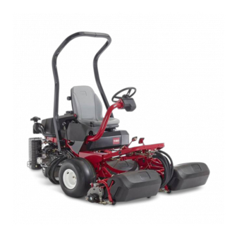
Toro Greensmaster 3250-D Operator's Manual
2-wheel drive traction unit
Hide thumbs
Also See for Greensmaster 3250-D:
- Operator's manual (44 pages) ,
- Service manual (260 pages) ,
- Quick start manual (2 pages)

Related Manuals for Toro Greensmaster 3250-D


Summary of Contents for Toro Greensmaster 3250-D
- Page 1 Form No. 3422-517 Rev A Greensmaster ® 3250-D 2-Wheel Drive Traction Unit Model No. 04384—Serial No. 401380001 and Up *3422-517* A Register at www.Toro.com. Original Instructions (EN)
- Page 2 Section 4442, maintained in register your product. effective working order or the engine is constructed, Whenever you need service, genuine Toro parts, or equipped, and maintained for the prevention of fire. additional information, contact an authorized Toro...
-
Page 3: Table Of Contents
This manual uses 2 words to highlight information. Servicing the Air Cleaner ........34 Important calls attention to special mechanical Servicing the Engine Oil........34 information and Note emphasizes general information Fuel System Maintenance ........36 worthy of special attention. Draining Water from the Fuel Filter.... -
Page 4: Safety
Safety • Do not put your hands or feet near moving components of the machine. • Do not operate the machine without all guards This machine has been designed in accordance with and other safety protective devices in place and EN ISO 5395:2013 and ANSI B71.4-2017 when 18 kg working on the machine. - Page 5 decal93-8068 decal93-6681 93–8068 93-6681 1. Read the Operator's Manual for instructions on locking and 1. Cutting/dismemberment—hazard, fan-stay away from unlocking the steering arm. moving parts. decal93-6689 93-6689 decal93-6686 93-6686 1. Warning—do not carry passengers. 1. Hydraulic fluid 2. Read the Operator's Manual. decal127-6114 127-6114 1.
- Page 6 decal104-7729 104–7729 1. Warning—read the 2. Cutting/dismemberment instructions before hazard; hand or foot—shut servicing or performing off the engine and wait for maintenance. moving parts to stop. decal93-8062 93-8062 1. To lock the parking brake, 3. Parking-brake lock press the brake pedal and the parking-brake lock.
- Page 7 decalbatterysymbols Battery Symbols Some or all of these symbols are on your battery. 1. Explosion hazard 6. Keep bystanders a safe distance away from the battery. 2. No fire, open flame, or 7. Wear eye protection; smoking explosive gasses can cause blindness and other injuries.
- Page 8 decal115-8156 115-8156 1. Reel height 3. 8–Blade cutting unit 5. 14–Blade cutting unit 7. Fast 2. 5–Blade cutting unit 4. 11–Blade cutting unit 6. Reel speed 8. Slow...
-
Page 9: Setup
Setup Loose Parts Use the chart below to verify that all parts have been shipped. Procedure Description Qty. Seat Mount the seat to the base. Nut (5/16 inch) – No parts required Activate and charge the battery. Roll bar Bolt (5/8 x 4-1/2 inch) Install the roll bar. -
Page 10: Mounting The Seat
Media and Additional Parts Description Qty. Operator's Manual Review it before operating the machine. Engine owner's manual Use it to reference engine information. Declaration of Conformity For CE compliance Noise rating certificate Ignition keys Start the engine. Note: Mounting fasteners for the Greensmaster 3250-D cutting units are included with the cutting units. -
Page 11: Activating And Charging The Battery
Activating and Charging the Battery No Parts Required Procedure g001197 Use only electrolyte (1.265 specific gravity) to fill the Figure 5 battery initially. 1. Electrolyte WARNING Allow approximately 20 to 30 minutes for the Battery terminals or metal tools could short electrolyte to soak into the plates. -
Page 12: Installing The Roll Bar
to the negative (–) terminal of the battery and secure them with the bolts and nuts (Figure Slide the rubber boot over the positive terminal to prevent a possible short from occurring. WARNING Incorrect battery cable routing could damage the tractor and cables, causing sparks. Sparks can cause the battery gasses to explode, resulting in personal injury. -
Page 13: Mounting The Front Carrier Frames
Mounting the Front Carrier Adjusting the Carrier Frame Frames Rollers Parts needed for this procedure: No Parts Required Carrier frame Procedure Spacer Position the machine on a level surface and Bolt (1/2 inch x 3-1/4 inches) lower the cutting unit carrier frames to the floor. Locknut (1/2 inch) Verify that there is 13 mm (1/2 inch) clearance between the carrier frame rollers and the floor. -
Page 14: Installing The Oil Cooler
Slide the sleeve back on each ball joint receiver and hook the receiver onto the cutting unit ball stud (Figure 10). Installing the Oil Cooler Optional No Parts Required Procedure If you are operating the machine in an area where ambient temperatures range from 20 to 49°C (70 to 120°F), or if you use the machine for heavy-duty use (mowing other areas than greens, such as fairways or... -
Page 15: Marking The Outer Grass Baskets
g008420 Figure 11 1. Mounting bolts 2. Drive motor g005115 Figure 12 Coat the motor spline shaft with clean grease 1. Alignment strip 3. Cut grass on right and install the motor by rotating the motor 2. Approximately 12.7 cm (5 4. - Page 16 g008423 g008422 Figure 13 Figure 15 1. Transport plate 4. Offset lift hook 1. Transport plate 4. Link hook 2. Adjusting screw 5. 25 mm (1 inch) 2. Adjusting screw 5. 22 mm (7/8 inch) 3. Transport-plate mounting 3. Transport —late mounting screw screw On cutting units equipped with a chain link or...
-
Page 17: Adding Rear Ballast
Adding Rear Ballast Installing the CE Decals Parts needed for this procedure: Parts needed for this procedure: Rear Weight Kit (Part No. 100-6442 or Part No. Warning decal (Part No. 136-8505) 99-1645; purchase separately) CE mark decal 18 kg Calcium chloride (purchase separately) (40 lb) Procedure Procedure... -
Page 18: Burnishing The Brakes
Product Overview Controls Traction Pedal The traction pedal (Figure 18) has 3 functions: to make the machine move forward, to move it backward, and to stop the machine. Press the top of the pedal to move forward and the bottom of the pedal to move backward or to assist in stopping when moving forward. - Page 19 Parking-Brake Tab • position—neutral position; use when backlapping the reels To set the parking brake, press the brake pedal, then • position—use when cutting grass IDDLE press the parking-brake tab (Figure 18) to engage the brakes. Disengage the tab by pressing the brake •...
- Page 20 Raise/Lower Mow Control Seat-Adjustment Lever Moving the control (Figure 20) forward during cutting The seat-adjustment lever on the left side of the seat operation lowers the cutting units and starts the reels. (Figure 22) allows an 18 cm (7 inch) foreward and Pull back on the control to stop the reels and raise rearward adjustment of the seat.
-
Page 21: Specifications
Do not operate the machine unless they your Authorized Service Dealer or authorized Toro are functioning properly. distributor or go to www.Toro.com for a list of all approved attachments and accessories. • Before mowing, always inspect the machine to... -
Page 22: Filling The Fuel Tank
Ethanol: Gasoline with up to 10% ethanol (gasohol) ◊ Painted surfaces may be damaged by or 15% MTBE (methyl tertiary butyl ether) by volume biodiesel blends. is acceptable. Ethanol and MTBE are not the same. ◊ Use B5 (biodiesel content of 5%) or lesser Gasoline with 15% ethanol (E15) by volume is not blends in cold weather. -
Page 23: During Operation
Do not operate the machine while ill, tired, or under the influence of alcohol or drugs. • Use accessories, attachments, and replacement parts approved by The Toro® Company only. • Never carry passengers on the machine and keep bystanders and pets away from the machine during operation. -
Page 24: Breaking In The Machine
• speed or direction. Make turns slowly and Initial start up of a new engine. gradually. • The engine has ceased running due to lack of fuel. – Do not operate a machine under any conditions • Maintenance has been performed upon fuel where traction, steering, or stability is in system components. -
Page 25: Shutting Off The Engine
Checking the Traction Pedal Note: If fluid leaks continue to appear, contact your authorized Toro distributor for assistance Perform the following system checks daily to ensure and, if necessary, replacement parts. that the interlock system is operating correctly:... -
Page 26: Driving The Machine Without Mowing
Checking the Operator’s Presence Mowing the Green Switch Important: If the leak detector alarm (if equipped on your model) sounds or you notice an oil leak Sit on the seat, move the traction pedal to the while cutting on a green, immediately raise the position, move the functional control EUTRAL cutting units, drive directly off the green, and... - Page 27 the sight line; i.e., keep the steering wheel edge aligned with a point that is always kept the same distance away from the front of the machine. As the front edges of the baskets cross the edge of the green, pull back the raise/lower mow lever rearward and hold it until all the cutting units have risen.
-
Page 28: After Operation
Inspecting and Cleaning Empty the grass baskets of all clippings before you transport the machine to the next green. after Mowing Note: Heavy wet clippings place an undue strain on the baskets and add unnecessary After mowing, thoroughly wash the machine with a weight to the machine, which increases the load garden hose without a nozzle so that excessive water on the machine systems (e.g., engine, hydraulic... -
Page 29: Towing The Machine
Towing the Machine In case of an emergency, you can tow the machine for up to 0.4 km (1/4 mile). Important: Do not tow the machine faster than 3 to 5 km/h (2 to 3 mph) to avoid damaging the drive system. -
Page 30: Maintenance
Determine the left and right sides of the machine from the normal operating position. Note: Download a free copy of the electrical or hydraulic schematic by visiting www.Toro.com and searching for your machine from the Manuals link on the home page. -
Page 31: Recommended Maintenance Schedule(S)
Recommended Maintenance Schedule(s) Maintenance Service Maintenance Procedure Interval • Torque the wheel nuts. After the first hour • Check the tension on the alternator belt. After the first 8 hours • Torque the wheel nuts. After the first 10 hours •... -
Page 32: Daily Maintenance Checklist
Daily Maintenance Checklist Duplicate this page for routine use. Maintenance Check Item For the week of: Mon. Tues. Wed. Thurs. Fri. Sat. Sun. Check the safety-interlock operation. Check the instrument operation Check the brake operation. Check the fuel filter/water separator. Check the fuel level. -
Page 33: Lubrication
Lubrication • Traction pedal pivot (1) (Figure Greasing the Machine Service Interval: Every 50 hours (Also, apply grease after every washing.) The machine has grease fittings that must be lubricated regularly with No. 2 general-purpose, lithium-base grease. If the machine is operated under normal conditions, lubricate all bearings and bushings after every 50 hours of operation. -
Page 34: Engine Maintenance
2. Dust cap 4. Outlet valve • Alternate oil: SAE 15W–40 Toro Premium Engine oil is available from your Remove the cover from the air-cleaner body. distributor in the 10W–30 viscosity. See the parts Before removing the filter, use low pressure air catalog for part numbers. - Page 35 on the dipstick, add oil to bring the oil level to the F mark. Do not overfill. Important: Keep the engine oil level between the upper and lower limits on the oil gauge; the engine may fail if you run it with too much or too little oil. Park the machine on a level surface, shut off the engine and remove the key.
-
Page 36: Fuel System Maintenance
Fuel System Maintenance Draining Water from the Fuel Filter Service Interval: Before each use or daily Position the machine on a level surface and shut off the engine. Place a drain pan under the fuel filter. Open the drain plug on the fuel filter approximately one turn and drain any accumulated water (Figure... -
Page 37: Replacing The Fuel Filter
Replacing the Fuel Filter Dispose of the fuel and filter according to local regulations. Service Interval: Every 800 hours Close the fuel shutoff valve (Figure 37) below Inspecting the Fuel Lines the fuel tank. and Connections Service Interval: Every 2 years Inspect the fuel lines for deterioration, damage, or loose connections. -
Page 38: Electrical System Maintenance
Electrical System WARNING Incorrect battery cable routing could damage Maintenance the tractor and cables, causing sparks. Sparks can cause the battery gasses to Electrical System Safety explode, resulting in personal injury. • Always disconnect the negative (black) • Disconnect the battery before repairing the battery cable before disconnecting the machine. -
Page 39: Drive System Maintenance
Drive System Loosen both jam nuts securing the traction-control cable to the bulkhead on the Maintenance hydrostat (Figure 40). Ensure that the jam nuts are loosened equally and sufficiently to allow adjustment. Checking the Tire Pressure Service Interval: Before each use or daily Vary the tire pressure for the front wheels, depending upon your turf conditions, from a minimum of 55 kPa (8 psi) to a maximum of 83 kPa (2 psi). -
Page 40: Adjusting The Transport Speed
Adjusting the Transport Adjusting the Mowing Speed Speed The machine is adjusted at the factory, but speed may Obtaining the Maximum Transport be varied if desired. Speed Loosen the jam nut on the trunnion bolt (Figure 42). The traction pedal comes adjusted for Loosen the nut securing the lock and mow maximum-transport speed, but you may need brackets on the pedal pivot. -
Page 41: Cooling System Maintenance
Cooling System Clean the screen and install it. Maintenance Checking the Engine-Coolant Level Cooling System Safety The capacity of the cooling system is approximately • Swallowing engine coolant can cause 3.2 L (3.3 US qt). poisoning; keep out of reach from children and pets. -
Page 42: Brake Maintenance
Brake Maintenance Adjusting the Brakes A brake adjustment rod is located on each side of the machine so that you can adjust the brakes equally. Burnishing the Brakes While moving forward in transport speed, press Firmly apply the brakes and drive the machine at the brake pedal;... -
Page 43: Belt Maintenance
Belt Maintenance Controls System Maintenance Adjusting the Alternator Belt Adjusting the Cutting Unit Lift/Drop Service Interval: After the first 8 hours Ensure that the belt is properly tensioned to ensure The cutting unit lift/drop circuit comes with a proper operation of the machine and prevent flow-control valve (Figure 47). -
Page 44: Hydraulic System Maintenance
Toro. This fluid is compatible with the elastomers used Servicing the Hydraulic in Toro hydraulic systems and is suitable for a wide-range of temperature conditions. This fluid is Fluid compatible with conventional mineral oils, but for... -
Page 45: Checking The Hydraulic Lines And Hoses
Service Interval: After the first 50 hours Every 800 hours Hydraulic Fluid Capacity: 25.7 L (6.8 US gallons) If the fluid becomes contaminated, have your authorized Toro distributor flush the system. Contaminated fluid looks milky or black when compared to clean fluid. -
Page 46: Cutting Unit Maintenance
Cutting Unit Maintenance Blade Safety Refer to and complete the procedure in Maintenance Safety (page 30). A worn or damaged blade or bedknife can break, and a piece could be thrown toward you or bystanders, resulting in serious personal injury or death. •... -
Page 47: Backlapping The Reels
Backlapping the Reels WARNING Contact with the reels or other moving parts can result in personal injury. • Keep your hands and clothing away from the reels or other moving parts. • Never attempt to turn the reels by hand or foot while the engine is running. - Page 48 When finished, return the backlap lever to the F position, move the reel speed knob to the desired reel-speed setting, lower the seat, and wash all lapping compound off of the cutting units. Adjust cutting unit reel to bedknife as needed.
-
Page 49: Storage
Storage If you wish to store the machine for a long period of time, perform the following steps prior to storage: Remove accumulations of dirt and old grass clippings. Sharpen the reels and bedknives, if necessary; refer to the cutting unit Operator's Manual. - Page 50 The Way Toro Uses Information Toro may use your personal information to process warranty claims, to contact you in the event of a product recall and for any other purpose which we tell you about. Toro may share your information with Toro's affiliates, dealers or other business partners in connection with any of these activities. We will not sell your personal information to any other company.
- Page 51 While the exposure from Toro products may be negligible or well within the “no significant risk” range, out of an abundance of caution, Toro has elected to provide the Prop 65 warnings. Moreover, if Toro does not provide these warnings, it could be sued by the State of California or by private parties seeking to enforce Prop 65 and subject to substantial penalties.
- Page 52 Countries Other than the United States or Canada Customers who have purchased Toro products exported from the United States or Canada should contact their Toro Distributor (Dealer) to obtain guarantee policies for your country, province, or state. If for any reason you are dissatisfied with your Distributor's service or have difficulty obtaining guarantee information, contact the Toro importer.