
Related Manuals for Sony HVO-3300MT


Summary of Contents for Sony HVO-3300MT
- Page 1 4-596-607-13 (1) 2018-08 3D HD Video Recorder Instructions for Use Before operating the unit, please read this manual thoroughly and retain it for future reference. HVO-3300MT © 2016 Sony Corporation...
- Page 2 Indications for Use/Intended Use Symbols on the product Sony Medical Recorders are intended to record video and Consult the instructions for use still images from ultrasound, digital X-ray, endoscopic, Follow the directions in the instructions for laparoscopic and other compatible diagnostic imaging use for parts of the unit on which this symbol systems and surgical imaging systems.
- Page 3 All interface cables used to connect peripherals must be different branch circuits. shielded in order to comply with the limits for a digital For more information, consult qualified Sony service device pursuant to Subpart B of part 15 of FCC Rules. personnel.
- Page 4 • Portable RF communications equipment should be used no closer than 30 cm (12 inches) to any part of the HVO-3300MT. Otherwise, degradation of the performance of this equipment could result. • If the HVO-3300MT will be used adjacent to or stacked with other equipment, normal operation of the HVO-3300MT under such configurations should be verified via observation.
- Page 5 Guidance and manufacturer’s declaration – electromagnetic immunity The HVO-3300MT is intended for use in the electromagnetic environment specified below. The customer or the user of the HVO-3300MT should assure that it is used in such an environment. IEC 60601 Immunity test Compliance level Electromagnetic environment –...
- Page 6 Guidance and manufacturer’s declaration – electromagnetic immunity The HVO-3300MT is intended for use in the electromagnetic environment specified below. The customer or the user of the HVO-3300MT should assure that it is used in such an environment. IEC 60601 Immunity test Compliance level Electromagnetic environment –...
- Page 7 To assess the electromagnetic environment due to fixed RF transmitters, an electromagnetic site survey should be considered. If the measured field strength in the location in which the HVO-3300MT is used exceeds the applicable RF compliance level above, the HVO-3300MT should be observed to verify normal operation. If abnormal performance is observed, additional measures may be necessary, such as reorienting or relocating the HVO-3300MT.
- Page 8 Guidance and manufacturer’s declaration – electromagnetic immunity The HVO-3300MT is intended for use in an electromagnetic environment in which radiated RF disturbances are controlled. Portable RF communications equipment should be used no closer than 30 cm (12 inches) to any part of the HVO-3300MT.
- Page 9 2. Use the Power Cord (3-core mains lead) / Appliance This model (HVO-3300MT) is classified as a CLASS 1 Connector / Plug conforming to the proper ratings LASER PRODUCT. (IEC 60825-1: 2007 and IEC 60825- (Voltage, Ampere).
- Page 10 For the customers in Canada SONY LIMITED WARRANTY - Please visit http://www.sonybiz.ca/pro/lang/en/ca/article/resources- warranty for important information and complete terms and conditions of Sony’s limited warranty applicable to this product. For the customers in Europe Sony Professional Solutions Europe - Standard Warranty and Exceptions on Standard Warranty.
-
Page 11: Table Of Contents
Factory Assigned Functions......40 Table of Contents Other Assignable Functions ......41 Please Read First ........14 Usage Notes..........16 Chapter 3 Basic Recorder Operations Chapter 1 Overview Operation Flow........42 Step 1: Record......... 42 Features ...........17 Step 2: Capture Still Images ....43 System Configuration Example .....19 Step 3: Quick Playback ...... - Page 12 Playback...........54 [IP Address] Tab ......... 77 Playing Back the Most Recent Data [DNS Server] Tab ........78 (Quick Playback) ......... 54 [File Server] Tab ......... 78 Image Search ...........54 [Shared] Tab..........78 Specifying Search Conditions ..... 54 [NTP] Tab ........... 78 Viewing Thumbnails of Recorded Data ..
- Page 13 • Sony assumes no responsibility for damages, loss of income, or any claims from a third party arising out of use of the recorder or supplied software.
-
Page 14: Please Read First
If video or audio. To protect copyright, observe the you have any questions in this regard, contact your Sony following points carefully when using this unit. dealer. - Page 15 LCD panel • When placing the unit on a floor or other surface, make sure that the unit is equipped with the specified rubber The LCD panel fitted to this unit is manufactured with feet, and put the unit down carefully. If there are no feet, high precision technology, giving a functioning pixel mount the rubber feet first.
-
Page 16: Usage Notes
Use isopropyl alcohol with a concentration of 50% to 70% (v/v) or ethanol with a concentration of 76.9% to 81.4% (v/v) to clean the surface of the unit. In the event of operating problems If you should experience problems with the unit, contact your Sony dealer. -
Page 17: Chapter 1 Overview
Support for a variety of external storage media Record simultaneously to USB-compatible external hard The Sony HVO-3300MT has video input and output drives and USB memory devices via simple controls, or terminals, built–in HDD. It is possible to record input copy the data at a later time. - Page 18 If use of such a device is unavoidable, isolate its power supply by connecting an isolation transformer, or by connecting an isolator between the connecting cables. After implementing these measures, confirm that the reduced risk now conforms to IEC 60601-1 standards.
-
Page 19: System Configuration Example
(Streaming) CMDS-MS10MD / CMDS-MS20MD Endoscopic Content Management System device Master server HVO-3300MT Viewing terminal iPad application Card reader/ barcode reader Record data to up to two external storage media simultaneously. -
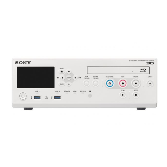
Page 20: Names And Functions Of Parts
Names and Functions of Parts Front Note Do not touch the laser pickup inside the BD drive V button The discharge of static electricity that may result from Use this to move the cursor up or select an item that touching the pickup may cause the drive to hang up, is above the current item. - Page 21 When recording or playback is not in progress, recorded data selected in the [Recording List] or pressing and holding this button for 5 seconds [Image List] screen. switches the Ch1 input signal with each long press. • Press this button while playback is paused to resume playback.
- Page 22 Note Never remove USB media when these indicators are blinking green. Supported USB devices • Use Sony USB media. • The connectors do not support all USB devices. • USB hubs and devices with built-in hubs are not supported. Warning Using this unit for medical purposes The connectors on this unit are not isolated.
-
Page 23: Rear
Rear AC IN connector Connect a power cord (not supplied) here. c ? (on) / a (off) switch (main power switch) Warning Set this to the ? (on) position to turn on the power. To Using this unit for medical purposes turn off the power, set the switch to the a (off) The connectors on this unit are not isolated. - Page 24 Ch2. DVI-D output connector (single link) Outputs DVI signals. Supported USB devices • Use Sony USB media. SDI input connectors 1 and 2 (BNC type) • The connectors do not support all USB devices. Input SD-SDI, HD-SDI, or 3G-SDI signals.
-
Page 25: Infrared Remote Control Unit (Rm-M010)
RGB input connector (15-pin mini D-sub) You can also use this button to pause playback. Inputs RGB signals. To resume playback, press this button again or press the B PLAY button. S VIDEO output connector (4-pin mini DIN) “PAUSE” appears on the front panel display during Outputs analog S-Video signals. -
Page 26: Status Displays
[General 1] tab. For details on this setting, see “[General To replace the lithium battery 1] Tab” (page 69). Use a Sony CR2025 lithium battery. Do not use any other type of battery with the remote control unit. Rec status display / idle status display... - Page 27 Idle status displays Orange: The maximum number of recorded data entries has been exceeded or the internal HDD is full. Gray: Status other than the above. h [External Storage 1] media status Displays the status of the external media for [External Storage 1] and its remaining capacity time.
-
Page 28: External Device Status Displays
Playback status displays If either of the two streams for 2-stream 3D images is not being input, a “No signal” determination is made, and the signal name will blink. b External storage media status (1 and 2) Displays the statuses of external storage media 1 and 2 and their remaining capacity times. -
Page 29: Using The On-Screen Keyboard (Text Entry)
b Setting item Using the On-Screen Use the V , v , B , and b buttons to select an item, and press the ENTER button to display the setting screen Keyboard (Text Entry) for that item. You can select or enter setting values in the screens that appear. -
Page 30: Handling Discs
Select this and press the ENTER button to cancel text entry and close the on-screen keyboard. h [OK] Use Sony discs. When you select this and press the ENTER button, the text that appears in the entry box is applied and input in the settings screen. -
Page 31: Inserting And Removing Discs
Cleaning • Clean the disc with a soft cloth, wiping it from the center out. If the dust is heavy, wipe it with a soft cloth Press the center of the disc until it clicks into place to moistened with water, then wipe off the water with a ensure that it is placed securely. -
Page 32: Chapter 2 Preparation
Chapter 2: Preparation Turning the Unit On and Connections To turn on the unit Set the ? (on) / a (off) switch on the rear panel to the Connect a power cord (not supplied) to the AC IN ? (on) position. connector on the rear of the unit. -
Page 33: Configuring System Settings
Configuring System To completely shut off the power supply, set the ? (on) / Settings a (off) switch to the a (off) position, and then disconnect the power cord. Be sure to configure the system settings before you begin operating the unit. The system settings should be configured by the system administrator. -
Page 34: Configuring Recording Settings (User Settings)
displayed as options for selection. However, if [HD/ Configuring Recording SD Rec Mode] is set to [SD Record] in the [System Admin Settings] screen – [Function Settings] screen Settings (User Settings) – [Recording] tab, 3D input signals will not be displayed. -
Page 35: Configuring Image Quality Settings
To configure the output mode The setting specified here will become the default Select [Advanced], and press the ENTER button. setting for [Video Quality] in the [Recording The [Advanced] settings screen for the output mode Preparation] screen. appears. Configure still image settings in the [Still] area. Select the output mode. -
Page 36: Configuring Save Settings
[Advanced] appears when [Use] is selected. For Select the Ch2 recording method, select [Apply], and details on this setting, see “To configure Ch2 then press the ENTER button. recording settings” (page 36). You can select from [Do Not Link to Ch1], [Link to For details on Ch1/Ch2 simultaneous recording, see Ch1], and [Create 2D from Ch1]. - Page 37 screen – [Function Settings] screen – [General 1] Invalid symbols and character strings for the tab, the setting will return to the default setting. folder name ¥ / : ? * " < > | . \ These will be replaced with underscores (_).
-
Page 38: Configuring Print Settings
entire text cannot be displayed, “...” will be Configuring Print Settings displayed. Configure print settings for still images. Display the [Metadata] tab, and configure metadata output settings. [Metadata Output] You can select the printer for use from the [System Select the check boxes of the metadata items you Admin Settings] screen –... -
Page 39: Configuring Other Settings
[Caption] (video printers only) To configure settings for the PinP function, proceed Select whether to print a caption. to “Configuring PinP Settings” (page 39). The default setting is [Not Used]. If you are finished configuring settings, select [Caption Content] (video printers only) [Apply] and press the ENTER button. -
Page 40: Function Keys
Function Keys When using the unit, you can assign certain functions (recording, playback, etc.) to the function keys (F1 to F12) at the top of a USB keyboard and perform these functions with a single keystroke. We recommend assigning frequently used functions The [Edit] screen appears. -
Page 41: Other Assignable Functions
• [Recording]: Record video and audio. Tips • [Set Chapter]: Insert a chapter separator without saving a still image of the recording. • Switching the Ch1 input signal via the functions does • [Close Folder]: End the recording session. not change the [User Settings]. •... -
Page 42: Chapter 3 Basic Recorder Operations
Chapter 3: Basic Recorder Step 1: Record Operations Press the z REC button. z REC button Operation Flow This chapter describes how to record and play back videos and capture still images while viewing the display on the front panel of the unit and using only the buttons on the front panel. -
Page 43: Step 2: Capture Still Images
If the surgical procedure or examination is finished Step 2: Capture Still and you want to end the recording session, proceed to “Step 4: End Recording” (page 44) and perform the Images recording end procedure. Capture still images from live image transmissions. If you press the z REC button again, recording will start Up to 500 still images can be captured for a single again as a new recorded data entry. -
Page 44: Step 3: Quick Playback
Step 3: Quick Playback Step 4: End Recording Play back data recorded in Step 1. End the recording session to stop recording to the internal HDD and stop transfer to external media. This operation Press the B PLAY button. is referred to as “closing a folder.” Press the x STOP button to stop recording. -
Page 45: Chapter 4 Recording And Playback
Enter patient information. Chapter 4: Recording and Patient information entry can be skipped. Playback [Patient ID] Enter an identification number for the patient. Recording Preparation Certain symbols (¥ / : ? * " < > | . \) cannot be used for the patient ID. -
Page 46: Using A Usb Keyboard For Patient Information And Data Storage Settings
• When a storage destination other than a server is Tips configured and [Prohibit USB/BD/DVD] is set to [Use] in the [System Admin Settings] screen – • When [CMS Mode] is set to [Use] in the [System [Function Settings] screen – [General 1] tab, the Admin Settings] screen –... -
Page 47: Registering Multiple Patients In Advance
Select [Execute], and press the ENTER button. Registering Multiple Patients in The [Recording Preparation] screen appears again, Advance and the patient information will be applied in the [Recording Preparation] screen. You can register information for multiple patients of procedures and examinations in advance. By doing so, you can simply select the patient from the registered To edit registered patient settings patient list on the day of the procedure or examination and... -
Page 48: Registering Patients From Mwl
To search for patients Registering Patients from MWL Patient information can be obtained from MWL and entered in the [Recording Preparation] screen. Modalities are always used in searches. When search conditions are specified, the search will be performed Tips using the specified conditions and modalities. •... -
Page 49: Recording
“Recording Preparation” (page 45). For details on how to record via contact switch, contact your local Sony representative. Note on the auto delete function for recorded data Whenever the remaining capacity on the unit’s internal... -
Page 50: Capture Still Images
After For details on contact switch controls, contact your local 24 hours, recording will stop automatically, and the Sony representative. “close folder” is performed. Recorded data directory Manual Still Image Capture Video data is stored in one of the following directories, depending on the system administrator settings. -
Page 51: Using The Ch1/Ch2 Simultaneous
• <uppermost folder of the external media>/<patient Using the Ch1/Ch2 name>/<recording start date (year, month, day, hour, minute, second)>/STILL/ Simultaneous Recording • <uppermost folder of the external media>/<patient ID_patient name>/STILL/ Function • <uppermost folder of the external media>/<patient name_recording start date (year, month, day, hour, minute, second)>/STILL/ This function allows automatic Ch2 recording during Ch1 recording. -
Page 52: Streaming Transmissions Of Surgical/Examination Images
Streaming Streaming Start and stop controls for streaming can be performed by Transmissions of assigning the following functions to the function keys on Surgical/Examination a USB keyboard. • [Streaming On]: Start streaming. Images • [Streaming Off]: Stop streaming. For details on function key settings, see “Using Function Keys”... -
Page 53: Superimposing Vitals Data Images (Pinp)
left, and right of the image, but the output will be Superimposing Vitals cropped. Data Images (PinP) Configuring Settings for Using the PinP Function By using the PinP function, you can superimpose the vitals data from the RGB input connector on recording Configure the following settings in the [User Settings] endoscopic images, for example, and record them. -
Page 54: Playback
Playback Image Search You can play back the most recent recorded data stored on You can search for recorded data stored on the unit’s the unit’s internal hard disk via simple controls. internal hard disk. Use the on-screen keyboard to enter text. You can also play back recorded data from search results. -
Page 55: Viewing Thumbnails Of Recorded Data
[2D/3D] To change the type of images for which to display Select whether the recorded data is 2D data or 3D thumbnails, select the [Display] box and press the data. ENTER button. The [Display] screen appears. Select [Video], [Still], or [All], and press the ENTER Select [Clear] and press the ENTER button to clear all button. -
Page 56: Sorting The Recorded Data List
Select [Execute], and press the ENTER button. Tips The recorded data is sorted according to the specified • Only the highlighted recorded data is played back. order. If Ch1 video does not exist, Ch2 video is played back. • In CMS mode, original recorded data for Ch1 is played back. -
Page 57: Processing Recorded Data
Select the [Operation] box, and press the ENTER Processing Recorded button. The [Operation] screen appears. Data Select [Print], and press the ENTER button. You can process recorded data stored on the unit’s The [Image List] screen appears again. internal hard disk in the following ways. •... - Page 58 Invalid symbols and character strings for the You can select from [BD/DVD], [USB 1], [USB 2], folder name and [SERVER]. ¥ / : ? * " < > | . \ These will be replaced with [File Server] underscores (_). If [SERVER] is selected as the external storage AUX, CON, NUL, These will result in errors during...
-
Page 59: Editing Patient Information
If you are copying to a BD/DVD disc or USB Select [Image List] for the operation box in the memory device, insert the media into the unit. [Recording List] screen. Select [Image List] for the operation box in the Select the recorded data in the [Recording List] [Recording List] screen. -
Page 60: Protecting Recorded Data
Select the check box of the recorded data for which Select [Execute], and press the ENTER button. you want to edit patient information. The recorded data is protected, and the icon appears. You can only edit patient information for one recorded data entry at a time. -
Page 61: Viewing Information On Recorded Data
Select [Execute], and press the ENTER button. Select [OK] when the confirmation message appears, and press the ENTER button. When deletion of the recorded data is complete, a notification message will appear. To return to the [Recording List] screen, press the ENTER button. -
Page 62: Playback Resolutions
Playback Resolutions For videos If the images were recorded in [Ch1 rec] mode or [Ch1/Ch2 Simul Rec] mode, the images will be played back in the resolution of the input connector at the time of recording, regardless of the recording resolution. Example: When S VIDEO image inputs are recorded as SD Input image Recorded... - Page 63 For still images Example: When DVI-D image inputs are played back Images are recorded using the same resolution as the input, and played back in 1920 × 1080 60i resolution. However, images are played back in 1920 × 1080 60p resolution during 3D line-by-line output. Playback image HD-SDI (1920 ×...
-
Page 64: Chapter 5 System Administrator Settings
Chapter 5: System Administrator Settings If password protection is enabled, a password entry screen will appear. Press the ENTER button when the system administrator settings notification screen appears. Displaying the [System The [System Admin Settings] screen appears Admin Settings] Screen Select the settings you want to configure, and press the ENTER button. -
Page 65: Language And Time Settings
List of time zones Language and Time Settings Time zone UTC-12:00 International Date Line West UTC-11:00 Coordinated Universal Time-11 Configure the display language and the display format for UTC-10:00 Hawaii the current date and time. UTC-09:00 Alaska Select [Language & Time Settings] in the [System UTC-08:00 Baja California Admin Settings] screen, and press the ENTER... - Page 66 Time zone Time zone UTC+01:00 Belgrade, Bratislava, Budapest, UTC+08:00 Taipei Ljubljana, Prague UTC+08:00 Beijing, Chongqing, Hong Kong SAR, UTC+01:00 West Central Africa Urumqi UTC+02:00 Athens, Bucharest UTC+09:00 Seoul UTC+02:00 Amman UTC+09:00 Yakutsk (RTZ 8) UTC+02:00 Istanbul UTC+09:00 Osaka, Sapporo, Tokyo UTC+02:00 Jerusalem UTC+09:30 Adelaide UTC+02:00 Cairo...
-
Page 67: Function Settings
The default setting is [1]. Function Settings [Change Patient Info.] Select whether to allow changes to patient information at any time. Configure initial settings for patient information, input The default setting is [Not Used]. signals, and other functions. Select [Function Settings] in the [System Admin [Input Signal 1] Tab Settings] screen, and press the ENTER button. -
Page 68: [Recording] Tab
You can select from the following input signals. The relationship between input resolutions and recording • [SDI ] (2D) modes is as follows. • [SDI ] (3D 2-stream) Input [HD Record] [HD/SD [SD Record] • [SDI ] (3D side-by-side) resolution Record] •... -
Page 69: [Auto Live] Tab
[Position] [Auto Live] Tab Select from [Top], [Bottom], [Left], and [Right] for the position in which captured still images are Configure initial settings for the auto live function. displayed while using the multi auto live function. The default setting is [Left]. [Auto Live] The four most recent still images are displayed when Select whether to use the auto live function. -
Page 70: [General 2] Tab
[Prohibit Remote Control] [Automatic Pause] Select whether to prohibit control of the unit via the Select whether to automatically pause recording when remote control buttons. there is no input signal. The default setting is [Not Used]. The default setting is [Not Used]. If you select [Use], recording will pause if there is no [Prohibit USB/BD/DVD] input signal for 10 minutes. -
Page 71: [Cms] Tab
[Not Used] in the [User Settings] screen – [Rec/ Streaming] tab, and [Streaming] is set to [Not Used], the setting will be fixed at the current selection. • For details on the content management system, contact your local Sony representative. -
Page 72: Device Settings
The correction value range will vary depending on your printer. Tips • The unit can recognize the Sony UP-DR80MD printer automatically. To have the unit recognize The [Gamma Curve] setting is only available for UP-DR80MD printers automatically, set the USB port Sony UP-D25MD printers. - Page 73 Display the [Other] tab, and perform logo file import Color: and other operations. Background: RGB (255, 255, 255) (white) Watermark: RGB (0, 0, 0) (black) The setting items will vary depending on your printer. • For letter size paper [High Speed Print] (UP-D25MD only) File format: 24-bit bitmap Select whether to enable high-speed printing.
-
Page 74: [Device 2] Tab
RS-232C connector. Select the printer to be used. In addition, configure the compatibility mode to be used with the Sony HVO-1000MD and HVO-3000MT. [Keyboard Mode] Select whether to use the soft keyboard (i.e., on-screen Select [Advanced] for [USB 7] or [RS-232C], and keyboard) or a USB keyboard in the [Recording press the ENTER button. -
Page 75: [Contact Switch] Tab
[Apply], and then press the ENTER button. The default setting is [PORT B]. You can select from [HVO-1000MD], [Recorder IN Signal] [HVO-3000MT], and [HVO-3300MT]. Select the signal that will be input to the monitor The default setting is [HVO-1000MD]. when outputting images from the unit. -
Page 76: Password Settings
[Set Index] Password Settings Add an index without saving a still image of the recording. To configure contact switch settings Configure password settings to prevent unauthorized changes to the [System Admin Settings]. When password protection is enabled, a password entry Select [Advanced] for the contact switch that will screen appears when [System Admin Settings] is selected perform the control, and press the ENTER button. -
Page 77: Network Settings
[Check New Password] Network Settings Reenter the new password. The new password is saved. Configure initial settings for the network and server. Select [Network Settings] in the [System Admin Settings] screen, and press the ENTER button. The [Network Settings] screen appears. Select a tab, and press the ENTER button. -
Page 78: [Dns Server] Tab
[IP Address] [Shared] Tab Enter the IP address. Configure the necessary settings for using a server as the [Subnet Mask] storage destination. Enter the subnet mask. [User Name] [Default Gateway] Enter a user name. Enter the IP address for the default gateway. If you are only using a local network and not connecting [Password] to other networks, do not configure this setting. - Page 79 To configure the image size and quality Recording resolutions and streaming image sizes and qualities Configure the image size and quality to be used during streaming. Recording Quality setting Streaming image size resolution and quality 1920 × 1080p Best (24 Mbps) The selected setting is obeyed.
-
Page 80: Doctor List Registration
[External Media] Doctor List Registration Select the external storage media that will be used during simultaneous recording. Select [External Media 1] or [External Media 2] in the external storage settings screen, and select the external Register doctor names and initial settings for each doctor. media in the screen that appears. -
Page 81: [External Media] Tab
[Layout] Editing the Doctor List Select the number of still images to print on each sheet. The layouts that appear and the default setting will vary depending on your printer. To use the system settings, select [User Settings]. Select [Edit Doctor List] in the [System Admin Settings] screen, and press the ENTER button. -
Page 82: Deleting Doctors
Note Editing Cases If you change the doctor name, you will not be able to use the previous doctor name to search for recorded data attributed to that name. Edit cases and categories for surgical procedures and examinations, and create the list of cases that will be used in the various screens. -
Page 83: Sorting The Case List
Select [OK] when the confirmation message appears, To delete a category and press the ENTER button. Select the category you want to delete in the [Edit Category List] screen, select [Delete], and then press Sorting the Case List the ENTER button. Select [OK] when the confirmation message appears, Select the case you want to reposition in the [Edit and press the ENTER button. -
Page 84: Editing Category Names
Editing Category Names Auto Delete Settings Select the category you want to rename in the [Edit Category List] screen, select [Edit], and then press the Select whether to use the auto delete function, and ENTER button. configure the threshold value that will be used for the function. -
Page 85: Dicom Settings
[AE Title] DICOM Settings Enter the AE title. This item is available when [MWM] is set to [Use]. Up to 16 characters can be entered. Configure settings that are necessary for DICOM [Retry] transmissions of still images. Select whether to retry operations, such as accessing or searching MWL and confirming communication with the Select [DICOM Settings] in the [System Admin MWM server. -
Page 86: [Mwm Server 2] Tab
Communication confirmation starts. An indicator [MWM Server 2] Tab appears during confirmation. The results of confirmation appear when the process Configure MWM server settings. is complete. [Patient Name Component] Select [OK], and press the ENTER button. Select the patient name component to be obtained. The default setting is [1st Component]. -
Page 87: Chapter 6 Touch Panel And Mouse
– After applying the setting, the V , v , B , b , ENTER, and MENU buttons on the front panel of the unit and on the infrared remote control unit are disabled. • For details on supported touch panel monitors, contact your local Sony representative. -
Page 88: Screen Displays In Touch Panel / Mouse Mode
Screen Displays in Touch Panel / Mouse Mode The screens that appear in touch panel / mouse mode differ slightly from those that appear in standard mode. This section describes the main differences in the screens and buttons that appear. [MENU] Screen a [Patient Info.] Displays the patient ID, patient name, gender, and... - Page 89 [Ch2 Ext Storage] – When the recording method for Ch2 is set to The external storage destination for Ch2 recorded [Create 2D from Ch1] in the [Advanced] settings data is identical to that of Ch1. for [Ch2 Rec] in the [User Settings] screen – [Rec/Streaming] tab Ch2 image display and playback/recording/ –...
- Page 90 j HDD capacity / error indicator e [Change Settings] tab Allows you to configure image quality and still image Displays the internal HDD’s remaining capacity format settings. under normal conditions. If an error occurs, the error that appears on the front [Quality] panel display also appears here.
-
Page 91: [Status] Screen
The input signal for the “1” connector of each Still Image Playback Screen connector type will be recorded for Ch1. This screen appears during still image playback. [Ch1 Ext Storage] You can play back the still images in sequence using the Configures the external storage destination for Ch1 buttons at the bottom. -
Page 92: Chapter 7 Miscellaneous
Chapter 7: Miscellaneous Error Messages When contacting your local Sony representative, please indicate the error message and error ID. Front panel display Description Solution Error message Error ID SYSTEM ERR. 0100 to Motherboard error Restart the unit. (The unit will restart automatically for 0199 error ID 0600 to 0699 capture board errors.) If the error... - Page 93 Internal HDD warning or error An internal HDD error has occurred. Contact your local Sony representative. ERR.BATTERY – Battery dead The battery is dead. Contact your local Sony representative. WARN.HDD.2 – Corrupted files warning Corrupted files exist on the internal HDD. Perform recovery on the internal HDD.
-
Page 94: Troubleshooting
Be sure to check the following if a problem occurs. If the recovery, the database cannot be recovered. Contact your local Sony representative. problem persists, contact your local Sony representative. • Menu displays are cut off and not fully • The unit does not turn on when the 1 (on/ displayed. -
Page 95: Licenses
1280 × 1024 software source code. Recording Resolution For details on the source code, contact your local Sony 720 × 480i representative. However, be aware that Sony will not 720 × 576i answer questions concerning the data in the source code. - Page 96 Connectors Mass Input Connectors Approx. 6.5 kg (Approx. 14 lb. 5.3 oz.) SDI (BNC type) (2) Dimensions DVI-D (Single link) (2) 305.0 × 329.0 × 115.5 mm (12 × 13 × 4 in.) S VIDEO (Mini DIN 4-pin type) (1) (W ×...
- Page 97 DURING THE WARRANTY PERIOD OR AFTER EXPIRATION OF THE WARRANTY, OR FOR ANY OTHER REASON WHATSOEVER. • SONY WILL NOT BE LIABLE FOR CLAIMS OF ANY KIND MADE BY USERS OF THIS UNIT OR MADE BY THIRD PARTIES. • SONY WILL NOT BE LIABLE FOR THE LOSS,...
-
Page 98: Index
PinP settings 39 Index Playback 54 [General] tab 80 [Print] tab 80 [General 1] tab 69 [Print 1] tab 38 [General 2] tab 70 [Print 2] tab 39 Print settings 38 Auto delete function 49, 84 Printer settings 72 [Auto Live] tab 69 Printing 57 HDD indicator 21 Auto live 69...