Table of Contents
Advertisement
Quick Links
Advertisement
Table of Contents

Related Manuals for Star Micronics DP8340


Summary of Contents for Star Micronics DP8340
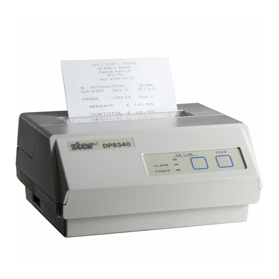
- Page 1 DOT MATRIX PRINTER DP8340 SERIES [PARALLEL INTERFACE] USERS MANUAL...
-
Page 2: Trademark Acknowledgments
STAR would greatly appreciate being informed of them. • The above notwithstanding, STAR can assume no responsibility for any errors in this manual. Federal Communications Commission Radio Frequency Interference Statement Statement of Radio Interference Regulations © Copyright 1986, 1999 Star Micronics Co., Ltd. -
Page 3: Table Of Contents
TABLE OF CONTENTS 1. OUTLINE ... 1 2. UNPACKING AND INSTALLATION ... 2 2-1. Unpacking ... 2 2-2. Installation of Paper Holders and Re-Roll Prevention Guard (Only Model DP-8340FC) ... 3 2-3. Handling Notes... 4 3. PART IDENTIFICATION AND NOMENCLATURE ... 5 3-1. -
Page 5: Outline
The DP8340 series of serial dot matrix printers is for use in ECR, POS, electronic instruments, banking machines and computer peripheral equipment. The DP8340 series include the following features; 2 color printing (Red and Black) High-speed bidirectional printing (2 line/sec, 40 columns per line) -
Page 6: Unpacking And Installation
2. UNPACKING AND INSTALLATION 2-1. Unpacking After opening the box, check if all necessary accessories are included. (A) Printer 1 Printer 2 User’s Manual 3 Paper Holders (B) Power Supply Unit 1 Power Supply Unit 2 User’s Manual 4 Re-Roll Prevention Guard 5 Ink Ribbon 6 DIP Switch Cover Figure 2-1. -
Page 7: Installation Of Paper Holders And Re-Roll Prevention Guard (Only Model Dp8340Fc)
2-2. Installation of Paper Holders and Re-Roll Prevention Guard (Only Model DP8340FC) Install the Paper Holders in the outermost holes in the rear of the printer. Figure 2-2. Installation of Paper Holders – 3 –... -
Page 8: Handling Notes
Install the Re-Roll Prevention Wire in the holes of the printer cover. Twisting the Wire as shown in the figure below, will make the installation easier. Figure 2-3. Installation of Re-Roll Prevention 2-3. Handling Notes (1) Install the printer near an easily accessible socket-outlet. (2) Place the unit on a flat and stable surface for operation. -
Page 9: Part Identification And Nomenclature
3. PART IDENTIFICATION AND NOMENCLATURE 3-1. Power Supply Unit DC Power Connector (Output) Shape of AC Power plug will vary according to destinations. Figure 3-1. Power Supply Unit – 5 –... -
Page 10: Printer
3-2. Printer Figure 3-2. Printer: Front View Figure 3-3. Printer: Rear View – 6 –... -
Page 11: Part Functional Description
3-3. Part Functional Description (1) AC Power Plug (2) DC Power Outlet (3) Printer Cover (4) POWER Lamp (5) ON LINE Lamp (6) ALARM Lamp (7) ON LINE Button (8) FEED Button (9) Interface Connector Connects the printer to host computers. Check that (10) DIP Switches (11) Peripheral Drive Output... -
Page 12: Installation Of Ink Ribbon And Paper
4. INSTALLATION OF INK RIBBON AND PAPER 4-1. Installation of Ink Ribbon (1) Turn power off, lift the Printer Cover up and remove it. Note: Be careful not to touch the print head immediately after printing, because it can get very hot. Figure 4-1. -
Page 13: Removal Of Ink Ribbon
Ribbon Life Figure 4-2. Installation of Ink Ribbon 4-2. Removal of Ink Ribbon Hold the spool and lift gently, rotating it until the ribbon sags. Push the ribbon detecting lever out, lift the spool until it comes off the shaft. Remove the second spool in a similar manner. -
Page 14: Paper Insertion
4-3. Paper Insertion 4-3-1. Model DP8340FC (1) Cut the Roll Paper end straight and square. Hold the roll so that the paper comes from the bottom. (2) Attach the Roll Paper to the Holders Paper by slipping one side of the roll onto the Hub and pulling the other Hub out to allow the roll to slip in place. -
Page 15: Model Dp8340Sc
4-3-2. Model DP8340SC Make a straight cut along the top of the paper, about 1/4 inch away from the sprocket holes, (as shown in the figure). If there is perforation, cut the paper on the perforation. Insert the paper squarely into the paper insertion slot until the ALARM lamp goes out. -
Page 16: Paper Removal
4-4. Paper Removal Cut the paper close to the slot and use the feed button until paper has passed completely through the printer. Note: Do not try to remove the paper by hand as it could become crooked and get jammed inside the printer. –... -
Page 17: Control Codes
CODE (0A) Print and line feed instruction FUNCTION The LF code causes the data in the line buffer to be printed, OUTLINE followed by a single line feed. When the line buffer is empty, only the feed takes place. CODE (0D) Print and line feed instruction FUNCTION... - Page 18 CODE (0F) FUNCTION Inverted print instruction This function causes the printing to be inverted. This code OUTLINE must be received at the beginning of a line. If this code is received anywhere other than at the beginning of a line, it is disregarded.
- Page 19 ESC R n CODE (1B) Select an international character. FUNCTION This command selects one of the international character sets OUTLINE in accordance with the value of “n” as shown below. n = 0 : U.S.A. International character set can be specified using the DIP Switches.
- Page 20 Relation Between Character Pattern Data and the Print Head ESC % 1 CODE (1B) Select download character FUNCTION This code specifies the download mode. Download char- OUTLINE acters defined by the previously explained <ESC>&0 code cannot be printed unless this code is first sent to the printer. ESC % 0 CODE (1B)
- Page 21 If the position into which the download character is written (the character code) is defined as (21) we have n character pattern data and the print head assigns the 9 pin as unused. Therefore, m If data m follows. Data Binary Hex.
- Page 22 ESC N n CODE (1B) Sets bottom margin in lines FUNCTION Upon receiving this code, the bottom margin is set to n lines. OUTLINE ESC O CODE (1B) Cancels bottom margin. FUNCTION Upon input of this code, bottom margin setting is cleared. OUTLINE CODE (0C)
- Page 23 Executed by BEL code and FS code after printing. CODE (07) FUNCTION Trigger peripheral unit drive (Deferred) Causes a peripheral drive pulse to be generated. This code is OUTLINE normally stored in the buffer and is performed as it is received from the data queue.
- Page 24 Character 1 LF (0A)H 2 CR (0D)H 3 SO (0E)H 4 DC4 (14)H 5 ESC-1 (1B)H (2D)H(01)H (1B)H (2D)H (31)H 6 ESC-0 (1B)H (2D)H(00)H (1B)H (2D)H (30)H 7 SI (0F)H 8 DC2 (12)H 9 ESC E (1B)H (45)H 10 ESC F (1B)H (46)H 11 ESC 4 (1B)H (34)H...
- Page 25 Character 23 ESC BEL (1B)H (07)H 24 BEL (07)H 25 FS (1C)H 26 SUB (1A)H 27 CAN (18)H Code Set peripheral unit drive pulse duration (default n Trigger peripheral unit drive 1 (Deferred) Trigger peripheral unit drive (Immediate) Trigger peripheral unit drive 2 (immediate) Clears print buffer –...
-
Page 26: General Specifications
6. GENERAL SPECIFICATIONS Printing method Number of print columns 40 columns, 12 CPI Print speed Print direction Line spacing Paper feed method Paper feed speed Character set Font configuration * Graphic Feed Not Available Character size Dot spacing Print area Print Buffer Interface Peripheral drive... - Page 27 Paper specification Paper type Size Paper width Roll diameter Thickness (single) (2 copy) Paper end Ink ribbon specification Color Ribbon material Ribbon size Spool Recommended ribbon Operating conditions Storage conditions Head life Printer reliability Ordinary and carbonless copy paper 114.3 mm (4.5 inches) 80 mm outer diameter (Max) 0.07 mm (52.3 g/m ) to 0.09 mm (64g/m...
- Page 28 Figure 6-1. Roll Paper and Print Area [Model DP8340FC] Figure 6-2. Sprocket-feed Paper and Print Area [Model DP8340SC] – 24 –...
- Page 29 Figure 6-3. External Dimensions (Printer) 36mm 120mm 2.0m Shape of AC Power plug will vary according to destinations. Figure 6-4. External Dimensions (Power Supply Unit) – 25 –...
-
Page 30: Interface
7-1. Interface Specifications This printer has a parallel interface to communicate with the computer. The operating specifications of the parallel interface are as follows. (1) Data transfer rate (2) Synchronization (3) Handshaking (4) Logic level 7-2. Interface Timing Figure 7-1. Interface Timing Diagram Signal Name DATA1-DATA8 (To Printer) -
Page 31: Connectors And Signals
7-3. Connectors and Signals Pin No.Signal Name IN/OUT STROBE DATA1-8 BUSY PAPER SELECTED 14-15 SIGNAL CHASSIS 19-30 RESET ERROR EXT GND 34-36 Figure 7-3. Parallel Interface Connector (Printer side) Signals when data is ready to be read.Signal gose from HIGH to LOW (for at least 0.5 microsec.) when data is available. -
Page 32: Setting Of The Dip Switches
7-4. Setting of the DIP Switches Switch Character Table (See below) Control cord CR 4 (*1) Printing Direction (Red printing) 5 (*2) Ink Ribbon International Character Set (See below) (*1) DIP Swich 4 should be set to OFF when you use 2-part sprocket paper having the seam on the right since the ribbon snags at the seam if shifted. -
Page 33: Peripheral Unit Drive Circuit
7-5. Peripheral Unit Drive Circuit The Control Board of this printer is equipped with a circuit for driving peripheral units (Paper Cutter, Take-Up Device, Cash Drawer, etc.) The 6P Modular Jack is used as the Drive Circuit. When using this circuit, connect the peripheral unit cable to the 6P Modular Jack (cable is not included). -
Page 34: Character Code List
8. CHARACTER CODE LIST 1) U.S.A. & Europe (DIP SW1: ON, SW2:ON) – 30 –... - Page 35 – 31 –...
- Page 36 2) IBM Character Set #1 (DIP SW1: OFF, SW2: ON) – 32 –...
- Page 37 – 33 –...
- Page 38 3) IBM Character Set #2 (DIP SW1: ON, SW2: OFF) – 34 –...
- Page 39 – 35 –...
- Page 40 4) JAPAN (DIP SW1: OFF, SW2: OFF) – 36 –...
- Page 41 – 37 –...
- Page 42 International Character Sets – 38 –...
-
Page 43: Font List
9. FONT LIST 1) U.S.A. & Europe (DIP SW1: ON, SW2:ON) – 39 –... - Page 44 – 40 –...
- Page 45 – 41 –...
- Page 46 2) IBM Character Set #1 (DIP SW1: OFF, SW2: ON) – 42 –...
- Page 47 – 43 –...
- Page 48 – 44 –...
- Page 49 3) IBM Character Set #2 (DIP SW1: ON, SW2: OFF) – 45 –...
- Page 50 – 46 –...
- Page 51 – 47 –...
- Page 52 4) JAPAN (DIP SW1: OFF, SW2: OFF) – 48 –...
- Page 53 – 49 –...
- Page 54 – 50 –...
- Page 55 International Character Sets – 51 –...
-
Page 56: When Power Is Supplied By The User
10. WHEN POWER IS SUPPLIED BY THE USER When printer power is supplied by the user rather than through the accessory power source unit, please be careful of the following points. Note 1: The power supply must be +12V pacitor (C = 4700µF/25V to 6800µF/25V) must be connected across the output of the power supply. - Page 57 +10% –5% 2 ~ 3A 6800µF/25V Other parameters may be determined by user. Figure 10-1. Power Supply Reference Circuit 100 ~ 200µF/25V VZD = 14V (1W) 4700 ~ 6800µF/25V 2SD633 (TOSHIBA) – 53 –...
- Page 58 - MEMO -...
- Page 59 ELECTRONIC PRODUCTS DIVISION STAR MICRONICS CO., LTD. 536 Nanatsushinnya, Shimizu, Shizuoka 424-0066 Japan Tel: 0543-47-0112, Fax: 0543-48-5271 Please access the following URL http://www.star-micronics.co.jp/service/sp_sup_e.htm for the lastest revision of the manual. OVERSEAS SUBSIDIARY COMPANIES STAR MICRONICS AMERICA, INC. 70-D Ethel Road West, Piscataway, NJ 08854 U.S.A Tel: 732-572-9512, Fax: 732-572-5095 STAR MICRONICS U.K.