Table of Contents
Advertisement
2018 Lennox Industries Inc.
©
Dallas, Texas, USA
General ...........................................................................1
Use of MiniSplit System During Construction................1
Included Parts.................................................................2
Model Number Identification ...........................................3
Typical System Components ..........................................4
System Dimensions ........................................................4
Outdoor Units ..............................................................4
Indoor Units .................................................................5
Indoor Unit Wall Mounts ..............................................5
System Clearances ........................................................5
Outdoor Unit ................................................................5
Multiple Outdoor Units .................................................6
Indoor Unit ...................................................................6
Torque Requirements for Caps and Fasteners...............7
Indoor Unit Installation ....................................................7
Unit Placement Considerations ...................................7
Determining Wall Mounting Plate Location ..................7
Installation of Wall Mounting Plate...............................7
Installation of Wall Sleeve............................................8
Indoor Unit Condensate Piping Connections ...............8
Outdoor Unit Installation .................................................9
Placement Considerations ...........................................9
Direct Sunlight and Rain Protection .............................9
Buried Refrigerant Pipe Protection ............................10
Securing the Outdoor Unit .........................................10
Refrigerant Piping Connections ....................................10
Adding Refrigerant for Longer Line Set ........................12
Leak Test and Evacuation ............................................12
Leak Test ...................................................................12
Triple Evacuation Procedure......................................13
Wiring Connections ......................................................13
Outdoor Unit .............................................................13
Indoor Unit .................................................................13
Wiring Diagrams (Outdoor Units) ..............................15
Wiring Diagrams (Indoor Units) .................................16
Unit StartUp .................................................................18
Troubleshooting ............................................................18
Test Run .......................................................................18
Pre-Checks ................................................................18
Procedure ..................................................................18
Test Run Checklist ........................................................18
DoubleCheck Line Set Connections............................18
Ambient Temperature is Below 63ºF (17ºC) .................19
INSTALLATION
INSTRUCTIONS
MCA Series Units
SINGLE-ZONE MINI-SPLIT SYSTEM
(115V and 208/230V)
50787901 6/2019
Supersedes 11/2018
THIS MANUAL MUST BE LEFT WITH THE OWNER
FOR FUTURE REFERENCE
WARNING
Improper installation, adjustment, alteration, ser vice
or maintenance can cause property damage, personal
injury or loss of life.
Installation and service must be performed by a li
censed professional HVAC installer (or equivalent) or a
service agency.
CAUTION
In order to avoid injury, take proper precaution when
lifting heavy objects.
General
Refer to the Product Specifications bulletin (EHB) for more
product information. These instructions are intended as
a general guide and do not supersede local or national
codes in any way. Authorities having jurisdiction should
be consulted before installation.
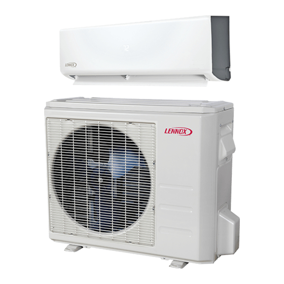
This wallmounted indoor unit is matched with an outdoor
air conditioner unit to create a minisplit system that uses
HFC410A refrigerant.
Use of Mini-Split System During
Construction
Lennox does not recommend the use of its minisplit
systems during any phase of construction. Very low return
air temperatures, harmful vapors and operation of the unit
with clogged or misplaced filters will damage the system.
However, minisplit systems may be used for cooling of
buildings under construction, if the following conditions
are met:
•
Air filter must be installed in the system and must be
maintained during construction.
•
Air filter must be replaced upon construction comple
tion.
•
The indoor wall unit assembly must be thoroughly
cleaned following final construction clean-up.
•
All mini-split operating conditions must be verified ac
cording to these installation instructions.
Advertisement
Table of Contents

Related Manuals for Lennox MCA Series


Summary of Contents for Lennox MCA Series
-
Page 1: Table Of Contents
Outdoor Unit Installation ..........9 Construction Placement Considerations ...........9 Direct Sunlight and Rain Protection ......9 Lennox does not recommend the use of its minisplit Buried Refrigerant Pipe Protection ......10 systems during any phase of construction. Very low return Securing the Outdoor Unit .........10 air temperatures, harmful vapors and operation of the unit Refrigerant Piping Connections ........10... -
Page 2: Included Parts
Included Parts Package 1 of 1 contains the following: 1 Assembled Indoor Unit The assembled indoor unit will include the following items: Parts Figure Quantity Parts Figure Quantity Installation instruction, ON/OFF Wireless controller 1 ea. MODE TIMER TEMP user guide and warranty TIMER FAN/SLC SLEEP... -
Page 3: Model Number Identification
Model Number Identification OUTDOOR SINGLE ZONE AIR CONDITIONER UNITS M C A 009 S 4 S 1 P Series Type Voltage M = MiniSplit L = 115V1 phase60Hz P = 208/230V1 phase60Hz Minor Design Sequence Unit Type 1 = 1st Revision C = Air Conditioner Refrigerant Circuits S = Single Circuit... -
Page 4: Typical System Components
Typical System Components System Dimensions Outdoor Units MCA009S4S, MCA012S4S, MCA081S4S 30-5/8 (778) 21-7/8 (556) 19-1/8 (486) (13) 11-7/8 (302) 30-3/8 (772) 2-3/4 2-1/2 ON/OFF SIDE VIEW FRONT VIEW (64) MODE TIMER (70) TEMP TIMER FAN/SLC SLEEP SWING DIRECT TURBO CLEAN FOLLOW 1/2 (13) DRAIN HOLE (bottom of unit) -
Page 5: Indoor Units
Indoor Units MWCA018S4 20-3/8 (518) 6-3/4 (171) 5-5/8 5-3/8 (137) (143) 2-1/4 (57) Wall-Mount 2-1/4 Unit Outline TOP VIEW (57) 2-3/8 (60) 38 (965) Left Rear Hole Right Rear Hole 2-1/2 in. (64 mm) 2-1/2 in. (64 mm) diameter diameter Figure 7. -
Page 6: Multiple Outdoor Units
Multiple Outdoor Units Height of Wall (C) Unit Height (A) CLEARANCE NOTES FOR MULTIPLE UNITS: If the height of the wall (C) is less than or equal to the height of the smallest unit (A), the distance from the unit to the wall (B) must be a minimum of 10 inches (254 mm). If 1/2 the height of the unit (A) is less than the height of the wall (C), the distance from the unit to the wall (B) must be a minimum of 12 inches (305 mm). -
Page 7: Torque Requirements For Caps And Fasteners
See the Lennox Service and Application Notes C081 for further details and information. Determining Wall Mounting Plate Location Table 1. Torque Requirements... -
Page 8: Installation Of Wall Sleeve
Installation of Indoor Unit on Wall Mounting Plate wall construction. Use the appropriate type of anchors for the application. 1. A length of field-provided flexible condensate piping 3. The wall mounting plate must be installed flush should be connected to the drain prior to securing the against the wall so that the indoor unit will be flush unit to the wall mounting plate. -
Page 9: Outdoor Unit Installation
pump has been installed, it must be checked to • Choose a location where the hot air discharged from the unit or the operation noise will not be a nuisance ensure proper operation. This check is part of the to neighbors. startup process which must be done by the installing contractor. -
Page 10: Buried Refrigerant Pipe Protection
IMPORTANT The construction of a canopy or shade is necessary because of an ambient limit control set to 122°F (50°C) to protect the electronics. If the outdoor unit is placed in direct sunlight it is possible that the limit may activate Four Field-Provided and shut down the unit. - Page 11 Table 3. Refrigerant Piping and Indoor Unit Connection Sizes Size Liquid Line Suction Line Lean Crude Burr (Btuh) Figure 23. Cutting Piping CANT ON THE OUTSIDE OF THE FLARE 5. Insulate the copper piping. 6. Insert a flare nut onto each pipe before flaring. MALE FLARE CONNECTION 7.
-
Page 12: Adding Refrigerant For Longer Line Set
IMPORTANT Do not over-tighten a flared joint. Flared connections should always be accessible and must be insulated to prevent condensation. Minimum Line Set Length - 10 ft. (3m) Maximum Line Set OUTDOOR UNIT INDOOR UNIT Length Maximum Line Set Length Maximum Maximum Elevation -... -
Page 13: Triple Evacuation Procedure
Triple Evacuation Procedure Outdoor Unit • Refer to unit nameplate for minimum circuit ampacity A Micron or Torr gauge must be used for this procedure. and maximum overcurrent protection size. 1. Discharge the oxygenfree nitrogen and evacuate the system to a reading of 8000 Microns (8 Torr) using all •... - Page 14 IMPORTANT This unit must be properly grounded and protected by a circuit breaker. The ground wire for the unit must not be connected to a gas or water pipe, a lightning conductor or a telephone ground wire. Do not connect power wires to the outdoor unit until all other wiring and piping connections have been completed. Do not install the unit near a lighting appliance that includes a ballast.
-
Page 15: Wiring Diagrams (Outdoor Units)
Wiring Diagrams (Outdoor Units) BLACK BROWN Indoor Unit BLUE BLACK Figure 29. 09 and 12K - 208/230VAC Outdoor Unit Wiring Diagram BLACK REACTOR L N Y/G CN 3 CN 1 CN 2 CN 16 CN 1A OUTDOOR MAIN BLUE CN 30 CN 29 CN 28 BLACK... -
Page 16: Wiring Diagrams (Indoor Units)
BLACK 3 BLUE L1L2 CN 6 CN 7 CN 8 CN 2 CN 3 L1 L2 OUTDOOR MAIN BLUE BLACK COMPRESSOR CN 17 CN 414 DC-FAN Figure 31. 18K and 24K 208/230VAC Outdoor Unit Wiring Diagram Wiring Diagrams (Indoor Units) FOR REMOTE ON/OF NOTE: COMPONENT IN DASH LINE IS OPTIONAL... - Page 17 FOR REMOTE ON/OF NOTE: COMPONENT IN DASH LINE IS OPTIONAL OR FIELD WIRING MODE REMOTE ON/OFF ON REMOTE ON/OFF OFF FACTORY SETTING (T1) (T2) CN10A D IS PLAY B O ARD ADAPTER BOARD CN 2 (C N2 01 CN 3 (C N3 CN 50 1 CN 40 2 OP TION AL...
-
Page 18: Unit Start-Up
Unit Start-Up Table 8. Indoor Unit Error Codes IMPORTANT Display Error Information Inverter compressor drive error Units should be energized 24 hours before unit startup to prevent compressor damage as a result of slugging. Test Run 1. Inspect all factory- and field-installed wiring for loose Pre-Checks connections. -
Page 19: Ambient Temperature Is Below 63ºf (17ºc)
Ambient Temperature is Below 63ºF (17ºC) After installation, confirm that all electrical wiring is installed in accordance with local and national regulations, and according to the installation instruction. You cannot use the wireless remote control to turn on the COOL function when the ambient temperature is below 63°F (17°C).