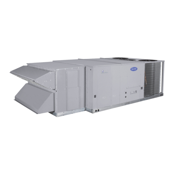
Carrier WeatherMaker 48TC Series Installation Instructions Manual
Single package rooftop with gas heat/electric cooling vertical air flow unit with puron (r-410a) refrigerant
Hide thumbs
Also See for WeatherMaker 48TC Series:
- Service and maintenance instructions (112 pages) ,
- Product data (101 pages) ,
- Installation instructions manual (60 pages)
Table of Contents
Advertisement
48TC units for installation in the United States contain use of Carrier's Staged Air Volume (SAV™) 2-
speed indoor fan control system. This complies with the U.S. Department of Energy (DOE) efficiency
standard of 2018.
48TC units for installation outside the United States may or may not contain use of the SAV 2-speed
indoor fan control system as they are not required to comply with the U.S. Department of Energy
(DOE) efficiency standard of 2018.
For specific details on operation of the Carrier SAV 2-speed indoor fan system refer to the Variable
Frequency Drive (VFD) Factory-Installed Option 2-Speed Motor Control Installation, Setup, and
Troubleshooting manual.
CONTENTS
SAFETY CONSIDERATIONS . . . . . . . . . . . . . . . . . . . . 1
GENERAL . . . . . . . . . . . . . . . . . . . . . . . . . . . . . . . . . . . 3
Rated Indoor Airflow (cfm) . . . . . . . . . . . . . . . . . . . . . 3
INSTALLATION. . . . . . . . . . . . . . . . . . . . . . . . . . . . . . 17
Job-Site Survey . . . . . . . . . . . . . . . . . . . . . . . . . . . . . 17
Step 1 - Plan for Unit Location . . . . . . . . . . . . . . . . 17
Step 3 - Inspect Unit . . . . . . . . . . . . . . . . . . . . . . . . 17
Step 4 - Provide Unit Support . . . . . . . . . . . . . . . . . 17
Step 5 - Field Fabricate Ductwork . . . . . . . . . . . . . 22
Step 6 - Rig and Place Unit . . . . . . . . . . . . . . . . . . . 22
Step 7 - Install Outside Air Hood (Factory-
Option) . . . . . . . . . . . . . . . . . . . . . . . . . . . . . . . . . . 23
Hood . . . . . . . . . . . . . . . . . . . . . . . . . . . . . . . . . . . . 24
Step 9 - Install Gas Piping. . . . . . . . . . . . . . . . . . . . 24
Step 11 - Make Electrical Connections . . . . . . . . . 27
DISCONNECT
Convenience Outlets . . . . . . . . . . . . . . . . . . . . . . . . . 29
Humidi-MiZer® Control Connections . . . . . . . . . . . . 31
EconoMi$er® X (Factory-Installed Option) . . . . . . . 33
Manufacturer reserves the right to discontinue, or change at any time, specifications or designs without notice and without incurring obligations.
Catalog No. 04-53480268-01
Single Package Rooftop with Gas Heat/Electric Cooling
Vertical Air Flow Unit with Puron
Installation Instructions
Printed in U.S.A.
Form 48TC-17-30-V-05SI
®
• CO2 SENSOR WIRING
PremierLink™ Control . . . . . . . . . . . . . . . . . . . . . . . 46
RTU Open Control System. . . . . . . . . . . . . . . . . . . . 46
Wiring Diagrams . . . . . . . . . . . . . . . . . . . . . . . . . . . . 46
Smoke Detectors. . . . . . . . . . . . . . . . . . . . . . . . . . . . 59
Step 12 - Adjust Factory-Installed Options . . . . . 60
Step 13 - Install Accessories . . . . . . . . . . . . . . . . . 60
Step 14 - Check Belt Tension . . . . . . . . . . . . . . . . 60
Pre-Start and Start-Up . . . . . . . . . . . . . . . . . . . . . . . 61
START-UP CHECKLIST . . . . . . . . . . . . . . . . . . . . CL-1
SAFETY CONSIDERATIONS
Installation and servicing of air-conditioning equipment can be
hazardous due to system pressure and electrical components. Only
trained and qualified service personnel should install, repair, or
service air-conditioning equipment.
Untrained personnel can perform basic maintenance functions of
cleaning coils and filters and replacing filters. All other operations
should be performed by trained service personnel. When working
on air-conditioning equipment, observe precautions in the litera-
ture, tags and labels attached to the unit, and other safety precau-
tions that may apply.
Pg 1
8-19
WeatherMaker
48TC 17-30
(R-410A) Refrigerant
Replaces: 48TC-17-30-V-04SI
®
Advertisement
Table of Contents

Related Manuals for Carrier WeatherMaker 48TC Series


Summary of Contents for Carrier WeatherMaker 48TC Series
-
Page 1: Table Of Contents
® (R-410A) Refrigerant Installation Instructions 48TC units for installation in the United States contain use of Carrier's Staged Air Volume (SAV™) 2- speed indoor fan control system. This complies with the U.S. Department of Energy (DOE) efficiency standard of 2018. - Page 2 Follow all safety codes, including ANSI (American National Stan- dards Institute) Z223.1. Wear safety glasses and work gloves. Use CAUTION quenching cloth for unbrazing operations. Have fire extinguisher CUT HAZARD available for all brazing operations. Failure to follow this caution may result in personal injury. It is important to recognize safety information.
-
Page 3: General
GENERAL AVERTISSEMENT These installation instructions cover the 48TC units with gas heat RISQUE D’INTOXICATION AU MONOXYDE and electric cooling. Units are pre-wired and pre-charged with en- CARBONE vironmentally sound Puron (R-410A) refrigerant at the factory. ® Si ces directives ne sont pas suivies, cela peut entraîner des See Fig. - Page 4 Position: 9 10 11 12 13 14 15 16 17 18 Example: Unit Heat Type 48 - Gas Heat Packaged Rooftop Packaging 0 = Standard Model Series - WeatherMaker ® TC - Standard Efficiency Electrical Options A = Non USA models - No (SAV) included C = Non-Fused Disconnect Heat Options G = Standard USA models - (SAV) included...
- Page 5 Fig. 2 — 48TC**17, 20 Vertical Airflow...
- Page 6 Fig. 3 — 48TC**17, 20 Back View and Condensate Drain Location...
- Page 7 Fig. 4 — 48TC**17, 20 Corner Weights and Clearances...
- Page 8 Fig. 5 — 48TC**17, 20 Bottom View...
- Page 9 Fig. 6 — 48TC**24-28 Vertical Airflow...
- Page 10 Fig. 7 — 48TC**24-28 Back View and Condensate Drain Location...
- Page 11 Fig. 8 — 48TC**24-28 Corner Weights and Clearances...
- Page 12 Fig. 9 — 48TC**24-28 Bottom View...
- Page 13 Fig. 10 — 48TC**30 Vertical Airflow...
- Page 14 Fig. 11 — 48TC**30 Back View and Condensate Drain Location...
- Page 15 Fig. 12 — 48TC**30 Corner Weights and Clearances...
- Page 16 Fig. 13 — 48TC**30 Bottom View...
-
Page 17: Installation
Install outdoor air hood INSTALLATION Install smoke detector tube Job-Site Survey Install combustion air hood Complete the following checks before installation. Install flue hood Consult local building codes and the NEC (National Elec- trical Code) ANSI/NFPA 70 for special installation 10. -
Page 18: Alternate Unit Support (In Lieu Of Curb Or Slab Mount)
NOTE: The gasketing of the unit to the roof curb is critical for a HOOD CARTON LOCATION watertight seal. Install gasket supplied with the roof curb as shown (REAR ACCESS PANEL) in Fig. 16-18. Improperly applied gasket can also result in air leaks and poor unit performance. - Page 19 Fig. 16 — Roof Curb Details — 17 and 20 Size Units...
- Page 20 Fig. 17 — Roof Curb Details — 24 and 28 Size Units...
- Page 21 Fig. 18 — Roof Curb Details — 30 Size Units...
-
Page 22: Step 5 - Field Fabricate Ductwork
Step 5 — Field Fabricate Ductwork CAUTION Cabinet return-air static pressure (a negative condition) shall not exceed 0.5 in. wg (87 Pa) with economizer or without economizer. UNIT DAMAGE HAZARD For vertical ducted applications, secure all ducts to roof curb and Failure to follow this caution may result in equipment damage. -
Page 23: Step 7 - Install Outside Air Hood
Step 7 — Install Outside Air Hood (Factory- APPLY SEAL STRIP Option) TO THE BACK OF THIS FLANGE APPLY SEAL STRIP The outside air hood for factory-option economizer and two-posi- TO THE BACK tion damper is shipped in knock-down form and requires field as- APPLY SEAL STRIP OF THIS FLANGE TO THE BACK... -
Page 24: Step 8 - Install Flue Hood And Combustion Air
COMBUSTION FLUE HOOD AIR HOOD Fig. 25 — Flue Hood and Combustion Air Hood Details 1. INSERT AIR SCREEN Step 9 — Install Gas Piping Installation of the gas piping must be in accordance with local building codes and with applicable national codes. In U.S.A., refer to NFPA 54/ANSI Z223.1 National Fuel Gas Code (NFGC). - Page 25 Table 5 — Natural Gas Manifold Pressure Ranges UNIT MODEL UNIT SIZE HIGH FIRE LOW FIRE 17, 20, 24, 3.0 in.wg 2.0 in.wg 48TC** 28, 30 (747 Pa) (498 Pa) Table 6 — LP Manifold Pressure Ranges UNIT MODEL UNIT SIZE HIGH FIRE LOW FIRE 17, 20, 24,...
-
Page 26: Factory-Option Thru-Base Connections
Density type and is labeled for use on gas lines. Apply tape per manufacturer’s instructions. 9” MINIMUM CLEARANCE Pressure-test all gas piping in accordance with local and FOR PANEL REMOVAL FROM national plumbing and gas codes before connecting piping to REGULATOR MANUAL GAS METER... -
Page 27: Step 11 - Make Electrical Connections
FIELD POWER SUPPLY If equipped with optional powered convenience outlet: the power source leads to the convenience outlet’s transformer primary are not factory connected. Installer must connect these leads accord- ing to required operation of the convenience outlet. If an always- energized convenience outlet operation is desired, connect the source leads to the line side of the unit-mounted disconnect. -
Page 28: Units With Factory-Installed Non-Fused Disconnect
UNITS WITH FACTORY-INSTALLED NON-FUSED DISCONNECT When installing units, provide a disconnect switch per NEC (Na- tional Electrical Code) of adequate size. Disconnect sizing data is provided on the unit informative plate. Locate on unit cabinet or within sight of the unit per national or local codes. Do not cover unit informative plate if mounting the disconnect on the unit cabinet. -
Page 29: Convenience Outlets
Such operation would invalidate any applicable mately in. (13 mm) under screw heads are exposed. Press the Carrier warranty. gasket over the screw heads. Slip the backing plate over the screw heads at the keyhole slots and align with the gasket; tighten the two screws until snug (do not over-tighten). -
Page 30: Factory-Option Thru-Base Connections (Electrical Connections)
This device can be a thermostat (field-supplied) or a PremierLink controller (available as factory-installed option or as field-installed accessory, for use on a Carrier Comfort Network or as a stand alone control) or the RTU Open for Building Management Sys-... -
Page 31: Humidi-Mizer® Control Connections
(contact closes on rise in space RH above control setpoint) (see Fig. 42) or a combination thermostat-humidistat control device such as Carrier’s EDGE ® Pro Thermidistat (see Fig. 43) with isolated contact set for dehu-... - Page 32 % RELATIVE HUMIDITY Fig. 42 — Accessory Field-Installed Humidistat ® Fig. 43 — Edge ® Pro Thermidistat ® Fig. 44 — Typical Humidi-MiZer Adaptive Dehumidification System Humidistat Wiring...
-
Page 33: Economi$Er® X (Factory-Installed Option)
EDGE Pro THERMIDISTAT Unit CTB THERMOSTAT O/W2/B SRTN ® Humidi-MiZer FIOP *Connection not required. Fig. 45 — Typical Rooftop Unit with Humidi-MiZer Adaptive Dehumidification System with Edge Pro Thermidistat Device SYSTEM COMPONENTS EconoMi$er ® X (Factory-Installed Option) The EconoMi$er X system includes an economizer module, 20k PRODUCT DESCRIPTION mixed air sensor, damper actuator, and either a 20k outdoor air The EconoMi$er X system is an expandable economizer control... -
Page 34: Inputs
Relay Digital Output Rating at 30 Vac (maximum power from Relative Humidity: Class 2 input only) — 1.5A run: 5% to 95% RH non-condensing 3.5A inrush at 0.45PF (200,000 cycles) or ECONOMIZER MODULE WIRING DETAILS 7.5A inrush at 0.45PF (100,000 cycles) Use Fig. -
Page 35: Interface Overview
Table 9 — Economizer Module - Right Hand Terminal Table 10 — HH57AC081 Sensor Wiring Terminations Blocks TERMINAL TYPE DESCRIPTION LABEL TYPE DESCRIPTION NUMBER LABEL Top Right Terminal Blocks S-BUS Communications AUX2 I 24 vac IN The first terminal is not used. S-BUS S-BUS (Enthalpy Control... -
Page 36: Menu Structure
To use the keypad when working with menus: MENU STRUCTURE • Press the ▲ (Up arrow) button to move to the previous Table 12 illustrates the complete hierarchy of menus and parame- menu. ters for the EconoMi$er ® X system. •... - Page 37 Table 12 — Menu Structure PARAMETER PARAMETER MENU PARAMETER DEFAULT RANGE AND NOTES VALUE INCREMENT FIRST STAGE COOLING DEMAND (Y1–IN) ECONO AVAIL YES/NO YES = economizing available; the system can use outside air for free cooling when required FIRST STAGE COOLING RELAY OUTPUT ECONOMIZING YES/NO YES = outside air being used for 1 stage cooling...
- Page 38 Table 12 — Menu Structure (cont) PARAMETER PARAMETER MENU PARAMETER DEFAULT RANGE AND NOTES VALUE INCREMENT EXHAUST STAGE 2 RELAY OUTPUT EXH2 OUT ON/OFF Output of AUX terminal; displays only if AUX = EXH2 ENERGY RECOVERY VENTILATOR ON/OFF Output of AUX terminal; displays only if AUX = ERV MECH COOL ON Displays stage of mechanical cooling that is active.
- Page 39 Table 12 — Menu Structure (cont) PARAMETER PARAMETER MENU PARAMETER DEFAULT RANGE AND NOTES VALUE INCREMENT Display order = MM/DD/YY INSTALL 01/01/10 Setting order = DD, MM, then YY. UNITS DEG F or C Sets economizer controller in degrees Fahrenheit or Celsius CONV = conventional;...
- Page 40 Table 12 — Menu Structure (cont) PARAMETER PARAMETER MENU PARAMETER DEFAULT RANGE AND NOTES VALUE INCREMENT SUPPLY AIR TEMPERATURE CALIBRATION MAT T CAL 0.0°F ±2.5°F Allows for the operator to adjust for an out of calibration temperature sensor. OUTSIDE AIR TEMPERATURE CALIBRATION OAS T CAL 0.0°F ±2.5°F...
- Page 41 Table 12 — Menu Structure (cont) PARAMETER PARAMETER MENU PARAMETER DEFAULT RANGE AND NOTES VALUE INCREMENT AUX2 IN is programmed for SHUTDOWN and 24 V has been SHUTDOWN ACTIVE applied to AUX 2IN terminal. DAMPER CALIBRATION ROUTINE RUNNING If DCV Auto enable has been programmed, when the W7220 is completing a calibration on the dampers, this alarm will display.
- Page 42 Table 14 — Dry Bulb Operation No DCV (CO Sensor) — 1 Speed Fan DEMAND OUTSIDE AIR CONTROLLED GOOD TO Y1-I Y2-I Y1-O Y2-O OCCUPIED UNOCCUPIED SPEED VENTILATION (DCV) ECONOMIZE HIGH 0v/Off 0v/Off MIN POS Closed NONE HIGH 24v/On 0v/Off MIN POS Closed HIGH...
- Page 43 Table 17 — Enthalpy Operation with DCV (CO Sensor) — 1 Speed Fan DEMAND OUTSIDE AIR CONTROLLED GOOD TO Y1-I Y2-I Y1-O Y2-O OCCUPIED UNOCCUPIED SPEED VENTILATION (DCV) ECONOMIZE HIGH 0v/Off 0v/Off VENTMIN Closed HIGH 24v/On 0v/Off VENTMIN Closed HIGH 24v/On 24v/On VENTMIN...
- Page 44 Table 20 — Enthalpy Operation without DCV (CO Sensor) — 2 Speed Fan DEMAND OUTSIDE AIR CONTROLLED GOOD TO Y1-I Y2-I Y1-O Y2-O OCCUPIED UNOCCUPIED SPEED VENTILATION (DCV) ECONOMIZE 0v/Off 0v/Off MIN POS Closed 24v/On 0v/Off MIN POS Closed HIGH 24v/On 24v/On MIN POS...
-
Page 45: Enthalpy Settings
ECONOMIZING DUAL ENTHALPY AVAILABLE HIGH LIMIT NOT AVAILABLE SINGLE ENTHALPY P2 (T,RH) (T,RH) TEMPERATURE Fig. 51 — Single Enthalpy Curve Boundaries Table 22 — Single Enthalpy and Dual Enthalpy High Limit Curves POINT P1 POINT P2 ENTHALPY TEMP. DRY TEMP. ENTHALPY HUMIDITY HUMIDITY... -
Page 46: Troubleshooting
TROUBLESHOOTING WARNING Alarms The economizer module provides alarm messages that display on ELECTRICAL SHOCK HAZARD the 2-line LCD. Failure to follow this warning could result in personal injury, NOTE: Upon power up, the module waits 60 minutes before property damage, or death. checking for alarms. - Page 47 Fig. 52 — PremierLink™ Wiring Diagram...
- Page 48 Fig. 53 — PremierLink Wiring Diagram with Humidi-MiZer ® System...
- Page 49 Fig. 54 — Typical RTU Open System Control Wiring Diagram...
- Page 50 Fig. 55 — Typical RTU Open System Control Wiring Diagram with Humidi-MiZer ® System...
- Page 51 Fig. 56 — 48TC**17-30 Control Wiring Diagram...
- Page 52 Fig. 57 — 48TC**17-30 Power Wiring Diagram, 208/230-3-60...
- Page 53 Fig. 58 — 48TC**17-30 Power Wiring Diagram, 460-3-60...
- Page 54 Fig. 59 — 48TC**17-30 Power Wiring Diagram, 575-3-60...
- Page 55 ® Fig. 60 — 48TC**17-30 Control Wiring Diagram with Humidi-MiZer System...
- Page 56 ® Fig. 61 — 48TC**17-30 Power Wiring Diagram with Humidi-MiZer System (208/230-3-60)
- Page 57 ® Fig. 62 — 48TC**17-30 Power Wiring Diagram with Humidi-MiZer System (460-3-60)
- Page 58 ® Fig. 63 — 48TC**17-30 Power Wiring Diagram with Humidi-MiZer System (575-3-60)
-
Page 59: Smoke Detectors
Smoke Detectors Smoke detectors are available as factory-installed options on 48TC models. Smoke detectors may be specified for supply air only, for return air without or with economizer, or in combina- tion of supply air and return air. The unit is factory-configured for immediate smoke detector shutdown operation;... -
Page 60: Step 12 - Adjust Factory-Installed Options
UNIT WITHOUT ECONOMIZER OR ECONOMIZER 2 POSITION DAMPER 2 POSITION DAMPER Fig. 67 — EconoMi$er ® IV Wiring • DDC interface (PremierLink) Step 12 — Adjust Factory-Installed Options • Louvered hail guard ECONOMI$ER IV OCCUPANCY SWITCH • Phase monitor control Refer to Fig. -
Page 61: Pre-Start And Start-Up
BLOWER PULLEY V-BELT MOTOR PULLEY MOTOR BELT DEFLECTION FORCE (LBS) BELT SMALLEST UNNOTCHED MOUNTING CROSS SHEAVE NOTCHED BELTS BELTS SECTION DIAMETER MOTOR MOUNTING BOLTS (4) USED USED PLATE 3.0-3.6 Fig. 69 — Belt Drive Motor Mounting A, AX 3.8-4.8 5.0-7.0 Pre-Start and Start-Up 3.4-4.2 —... - Page 62 © Carrier Corporation 2019 Manufacturer reserves the right to discontinue, or change at any time, specifications or designs without notice and without incurring obligations. Catalog No. 04-53480268-01 Printed in U.S.A. Form 48TC-17-30-V-05SI Pg 62 8-19 Replaces: 48TC-17-30-V-04SI...
- Page 63 START-UP CHECKLIST — 48TC 17-30 SINGLE PACKAGE ROOFTOP WITH ® HEAT/ELECTRIC COOLING WITH PURON (R-410A) REFRIGERANT NOTE: To avoid injury to personnel and damage to equipment or property when completing the procedures listed in this start-up checklist, use good judgment, follow safe practices, and adhere to the safety considerations/information as outlined in preceding sec- tions of this Installation Instruction document.
- Page 64 10. Restore set-points for thermostat and humidistat (Y/N) _____ REPEAT PROCESS FOR 2 COMPRESSOR SYSTEMS © Carrier Corporation 2019 Manufacturer reserves the right to discontinue, or change at any time, specifications or designs without notice and without incurring obligations. Catalog No. 04-53480268-01 Printed in U.S.A.