
Related Manuals for Sony Ericsson TT4031 (SE-GM29)


Summary of Contents for Sony Ericsson TT4031 (SE-GM29)
-
Page 1: Wireless Modem
TT4031 (SE-GM29) Wireless Modem TT4031 (SE-GM29) Wireless Modem Unit Sony Ericsson GM29 Original Equipment Manufactured by Sony Ericsson Mobile Communications International Owner’s Manual Owner’s Manual Rev 1.0 Page 1 of 1... -
Page 2: Customer Service
The Topp Consumer Products names, product names and logos are trademarks or registered trademarks of Topp Consumer Products. Other product names are trademarks or registered trademarks of their respective owners. The Sony Ericsson marble logo is the trademark or registered trademark of Sony Ericsson Mobile Communications AB. Ericsson is the trademark or registered trademark of Telefonaktiebolaget LM Ericsson. - Page 3 All rights not granted herein to the Proprietary Information are expressly reserved by Topp Consumer Products and Sony Ericsson Mobile Communications International, as applicable. You may use the Proprietary Information only as installed by Sony Ericsson Mobile Communications International on this TT4031 (SE-GM29) Wireless Modem product.
- Page 4 Products that may be enabled through the use of this TT4031 (SE-GM29) Wireless Modem product; (2) this TT4031 (SE- GM29) Wireless Modem product, if the serial number has been removed or defaced; (3) any repairs other than those provided by a Topp Consumer Products Authorized Service Facility; (4) malfunctions due to the use of this TT4031 (SE- GM29) Wireless Modem product in conjunction with accessories, products, or ancillary or peripheral equipment not furnished by Topp Consumer Products;...
- Page 5 YOU ACKNOWLEDGE THAT THIS TT4031 (SE-GM29) WIRELESS MODEM PRODUCT MAY ALLOW YOU, AT YOUR DISCRETION, TO RECEIVE WHERE AVAILABLE FROM A THIRD PARTY (SUCH AS YOUR DISTRIBUTOR) OTHER SERVICES ENABLED THROUGH THE USE OF THIS TT4031 (SE-GM29) WIRELESS MODEM PRODUCT, AND YOU IRREVOCABLY AND ABSOLUTELY AGREE THAT TOPP CONSUMER PRODUCTS SHALL NOT BE LIABLE IN CONNECTION WITH ANY ACTIONS, OMISSIONS, OR OTHER OCCURRENCES WITH RESPECT TO SUCH SERVICES.
- Page 6 The information contained in this document is the proprietary information of Sony Ericsson Mobile Communications International. The contents are confidential and any disclosure to persons other than the officers, employees, agents or subcontractors of the owner or licensee of this document, without the prior written consent of Sony Ericsson Mobile Communications International, is strictly prohibited.
-
Page 7: Table Of Contents
Table of Content Part 1: Overview ... 12 Introduction ... 13 Target Users... 13 Prerequisites ... 13 Manual Structure... 13 TT4031 (SE-GM29) Modem ... 15 Description... 15 Highlights ... 15 TT4031 (SE-GM29) in a Communication System... 16 Main Features and Services ... 18 Service and Support ... - Page 8 Error Codes ... 59 Examples on How to Use the AT Commands ... 62 Call Control... 63 AT+CPIN PIN Control ... 63 ATA Answer Incoming Call ... 63 ATD Dial... 64 ATH Hang up... 66 ATO Return to Online Data Mode... 66 ATP Select Pulse Dialing ...
- Page 9 AT*ELAM Ericsson Local Audio Mode ... 106 AT*EMIC Ericsson Microphone Mode... 106 AT*EMIR Ericsson Music Mute Indication Request... 107 AT*EXVC Ericsson SET External Volume Control... 108 Data - CSD/HSCSD ... 110 AT+CBST Select Bearer Service Type... 110 AT+CRLP Radio Link Protocol... 111 Data - GPRS...
- Page 10 AT+ILRR Cable Interface Local Rate Reporting ... 149 10.13 AT+IPR Cable Interface Port Command... 150 10.14 AT*E2ESC M2M Escape Sequence Guard Time... 151 10.15 Network ... 152 AT*E2CD Ericsson M2M Cell Description ... 152 11.1 AT*E2EMM Ericsson M2M Engineering Monitoring Mode ... 153 11.2 AT*E2SPN M2M Service Provider Indication ...
- Page 11 AT+CSCS Select Character Set ... 223 13.16 AT+CSMS Select Message Service... 224 13.17 Short Message Services - Cell Broadcast ... 226 AT+CNMI New Message Indications to TE ... 226 14.1 AT+CSCB Select Cell Broadcast Message Type... 226 14.2 SIM Application Toolkit ... 227 AT+CPIN PIN Control ...
-
Page 12: Part 1: Overview
Part 1: Overview Owner’s Manual Rev 1.0 Page 12 of 12... -
Page 13: Introduction
1. Introduction 1.1 Target Users TT4031 (SE-GM29) modems are designed to be integrated into machine- machine or man-to-machine communications applications. They are intended to be used by manufacturers, system integrators, applications developers and developers of wireless communications equipment. 1.2 Prerequisites It is assumed that the person integrating the TT4031 (SE-GM29) into an application has a basic understanding of the following: GSM networking;... - Page 14 Part 3 - Using AT Commands This section lists all the AT commands relevant to the TT4031 (SE-GM29), including their associated parameters. The purpose of part 3 is to give you detailed information about the function of each command in the AT command set.
-
Page 15: Tt4031 (Se-Gm29) Modem
2. TT4031 (SE-GM29) Modem 2.1 Description The dual band EGSM 900/1800 MHz TT4031 (SE-GM29) is a GSM/GPRS serial modem. The modem is a powerful and flexible device that can be used in a wide range of telemetry and telematics applications that rely on the remote exchange of data, voice, SMS or faxes via the GSM cellular network. -
Page 16: Tt4031 (Se-Gm29) In A Communication System
RS232 9-way serial interface 5 V - 32 V DC input 4-wire audio connection Antenna connection (FME male) FCC and PTCRB approved 2.3 TT4031 (SE-GM29) in a Communication System Figure 2.1 illustrates the main blocks of a wireless communication system using the TT4031 (SE-GM29). - Page 17 ETSI specifies a set of AT commands for controlling the GSM element of the modem; these commands are supplemented by Sony Ericsson specific commands. To find out how to work with AT commands, see “Part 3: Using AT Commands”. Figure 2.2 illustrates the interface between the modem and the application.
-
Page 18: Main Features And Services
2.4 Main Features and Services The modem performs a set of telecom services (TS) according to GSM standard phase 2+, ETSI and ITU-T. The services and functions of the modem are implemented by issuing AT commands over the RS232 serial interface. - Page 19 GSM network (for example, traffic reports). This feature is network dependent. SMS STATUS REPORT according to GSM 03.40. SMS COMMAND according to GSM 03.40. The maximum length of an SMS message is 160 characters when using 7- bit encoding. For 8-bit data, the maximum length is 140 characters. The modem supports up to 6 concatenated messages to extend this function.
- Page 20 2.4.5 Fax The TT4031 (SE-GM29) allows fax transmissions to be sent and received by commercial software installed on the application computer. Group 3 fax Classes 1 and 2 are supported. 2.4.6 Supplementary Services Call forwarding Call hold, waiting and multiparty Calling/called number identification Advice of charge USSD...
- Page 21 setting up and controlling communications to and from the GSM network; configuring the modem to communicate across the RS232 serial interface; and obtaining GSM network status information. For more detail on the AT commands supported by the TT4031 (SE-GM29) see “Alphabetical Listing of AT Commands”. 2.4.8 Interfacing with the TT4031 (SE-GM29).
-
Page 22: Service And Support
2.5 Service and Support To contact customer support please use the details below: Customer Support Topp Consumer Products 3055 NW 84 Avenue Miami, FL 33122 E-mail: telematic@toppcompanies.com Information about Topp Consumer Products and its products is available on the following web site: http://www.toppcompanies.com Owner’s Manual Rev 1.0... -
Page 23: Abbreviations
3. Abbreviations Abbreviation Explanations Adaptive Multi Rate Cell Broadcast Message Cell Broadcast Service Circuit Switched Data Data Circuit Terminating Equipment Data Terminal Equipment DTMF Dual Tone Multi Frequency Enhanced Full Rate Electro-Magnetic Compatibility E-OTD Enhanced Observed Time Difference Electrostatic Discharge ETSI European Telecommunication Standards Institute Federal Communications Commission... - Page 24 Short Message Service Terminal Adapter Terminal Equipment Telecom Services Owner’s Manual Rev 1.0 Page 24 of 24...
-
Page 25: Part 2: Integrating The Modem
Part 2: Integrating the Modem Owner’s Manual Rev 1.0 Page 25 of 25... -
Page 26: Mechanical Description
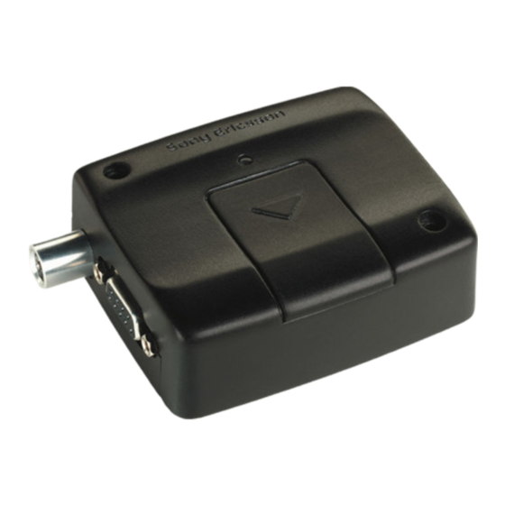
1. Mechanical Description 1.1 Overview The pictures below show the mechanical design of the TT4031 (SE-GM29) along with the positions of the different connectors and mounting holes. The TT4031 (SE-GM29) case is made of durable PC/ABS plastic. Figure 1.1 TT4031 (SE-GM29) viewed from the left side Figure 1.2 TT4031 (SE-GM29) viewed from the right side Please note the following: Mounting holes positioned at two of the corners make it possible... - Page 27 The SIM card is mounted in the modem. The pins and electrical characteristics or the modem’s various connectors are described in Electrical Description Information about the antenna connector is found in Antenna Connector Owner’s Manual Rev 1.0 Page 27 of 27...
-
Page 28: Physical Dimensions
1.2 Physical Dimensions Measurements are given in millimeters. See also Technical Data Owner’s Manual Rev 1.0 Page 28 of 28... -
Page 29: Electrical Description
2. Electrical Description All electrical connections to the TT4031 (SE-GM29) are designed to meet the standard air (4 kV) and contact (8 kV) discharge ESD tests, of EN 301 489-1. The modem uses the following industry standard connectors: RJ11 6-way (power connector) RJ9 4-way (handset connector) SIM card reader FME male coaxial jack (antenna connector) -
Page 30: Audio Connector
The power connector electrical characteristics are listed below: Signal HR_IN TO_IN 2.2 Audio Connector A 4-way RJ9 connector, as shown below, allows a telephone handset to be plugged into the modem, giving access to the microphone and earpiece signals. The connector may also be used to drive other analogue audio sub- systems or devices. - Page 31 Audio signal descriptions are listed below: Signal MICN BEARN BEARP MICP MICP and MICN are balanced differential microphone input signals. These inputs are compatible with an electret microphone. BEARP and BEARN are the speaker output signals. These are differential mode outputs. The electrical characteristics are given in the table below. Parameter Output level (differential) Output level (dynamic load = 32 Ω)
-
Page 32: Antenna Connector
2.3 Antenna Connector The antenna connector allows transmission of radio frequency (RF) signals between the modem and an external customer-supplied antenna. The modem is fitted with a 50 Ω FME male coaxial jack as shown below. The table below shows the antenna electrical characteristics: Parameter Nominal impedance Output Power... -
Page 33: Sim Card Reader
2.4 SIM Card Reader The TT4031 (SE-GM29) is fitted with a SIM card reader designed for 3 V and 5 V SIM cards. It is the flip-up type, which is lockable in the horizontal position and is accessed through a removable panel as shown below The SIM card reader includes a SIM presence switch. -
Page 34: Rs232 Serial Port
2.5 RS232 Serial Port The modem supports a standard RS232 serial interface (EIA/TIA 574) via its 9 pin Sub-D connector, shown below. In line with serial communication terminology the TT4031 (SE-GM29) serial modem should be considered as the data circuit-terminating equipment (DCE) and the external application or computer as the data terminating equipment (DTE). - Page 35 2.5.1 Serial Data The modem supports the standard data character format of 1 start bit, 8 bit data, no parity plus 1 stop bit, in total 10 bits per character. 2.5.2 Serial Data Signals - RD, TD The default baud rate is 9.6 kbps, however higher bit rates up to 460 kbps are supported.
-
Page 36: Real Time Clock
12 hours. 2.7 Software Updates It is possible and sometimes necessary to update the TT4031 (SE-GM29) software. Updates must be carried out by a Sony Ericsson approved technician. Please contact your supplier for details (see “Service and Support”). -
Page 37: Operation
3. Operation 3.1 Switching On the Modem There are two ways to switch on the modem, once power is applied. either assert TO_IN high for > 0.2 s; or activate the RS232 control line DTR, high for > 0.2 s. The modem is fully operational after 4 seconds. -
Page 38: Operating States/Led
3.4 Operating States/LED The modem has a green LED, as depicted below, which is used to indicate various operating states. These states are described in following table. Operating State After switching on the modem Switch off (Power down) or power removed Standby or talk No network, network search, no SIM card, no PIN entered... -
Page 39: Safety And Product Care
4. Safety and Product Care Please read the information in this section and the information in Installation of the Modem before starting your integration work. 4.1 Safety Instructions PLEASE READ THESE SAFETY INSTRUCTIONS AND KEEP A COPY OF THEM. Always ensure that use of the modem is permitted. The modem may present a hazard if used in proximity to personal medical electronic devices. -
Page 40: Sim Card Precautions
Ensure the d.c. cable, supplying power to the, TT4031 (SE- GM29) does not exceed 3 metres. For longer distances please contact Sony Ericsson (see “Service and Support”). To protect power supply cables and meet the fire safety requirements when the unit is powered from a battery or a high current supply, connect a fast 1.25A fuse in line with the... - Page 41 Never connect more than one modem to a single antenna. The modem can be damaged by radio frequency energy from the transmitter of another modem. Like any mobile station, the antenna of the modem emits radio frequency energy. To avoid EMI (electromagnetic interference), you must determine whether the application itself, or equipment in the application’s proximity, needs further protection against radio emission and the disturbances it might cause.
-
Page 42: Installation Of The Modem
5. Installation of the Modem This chapter gives you advice and helpful hints on how to integrate the TT4031 (SE-GM29) into your application from a hardware perspective. Please read the information given in Safety and Product Care and then the read the information in this section before starting your integration work. -
Page 43: How To Install The Modem
5.1.3 Connection of Components to TT4031 (SE-GM29). The integrator is responsible for the final integrated system. Incorrectly designed or installed, external components may cause radiation limits to be exceeded. For instance, improperly made connections or improperly installed antennas can disturb the network and lead to malfunctions in the modem or equipment. -
Page 44: Oem Labeling
Caution! Do not exceed a torque of 2.2 in lb (25 Ncm) when tightening the fixings screws. Excessive torque applied to the screws can crack the plastic case. 5.3 OEM Labeling Where the TT4031 (SE-GM29) is to be incorporated into an end product it is an FCC requirement that a label must be affixed to the outside of the end product with a statement similar to the following: “This device contains TX FCC ID: PY76220502-BV”. - Page 45 In any event, you should contact your local antenna manufacturer for additional information concerning antenna type, cables, connectors, antenna placement, and the surrounding area. You should also determine whether the antenna needs to be grounded or not. Your local antenna manufacturer might be able to design a special antenna suitable for your the application.
- Page 46 5.4.5 Possible Communication Disturbances Possible communication disturbances include the following: Noise can be caused by electronic devices and radio transmitters. Path-loss occurs as the strength of the received signal steadily decreases in proportion to the distance from the transmitter. Shadowing is a form of environmental attenuation of radio signals caused by hills, buildings, trees or even vehicles.
-
Page 47: Attachments
5.5 Attachments The TT4031 (SE-GM29) has been FCC certified using a number of attachments including: AC-DC Power Adaptor with Customized DC Lead (Model # PS001) Input 100-240 Va.c., 50/60Hz, 2m mains lead Output: 12 Vd.c. 1.25 A, 2 m d.c. lead with RJ11 connector. CE marked. Tri-band GSM Antenna (GSM/PCN/1.9GHz) (Model # ANT016) Covert fit spider patch antenna, self-adhesive pad, 0 dBi, 2 m RG174 cable... -
Page 48: Technical Data
6. Technical Data Data Features HSCSD (2+1) GPRS Class B (4+1) - P channels - Coding schemes CS1 - CS4 Short Message Service Features Voice Features Fax Features Data Storage SMS storage capacity Phone book capacity Owner’s Manual Up to 9.6 kbps Up to 19.2 kbps 85.6 kbps (subject to network support and terminal location) - Page 49 Power Supply Supply voltage range Power Consumption Supply voltage Power Down Mode Standby Mode (typical) Frequency Paging rate 900 MHz 1800 MHz Talk Mode (typical) Frequency Power Level 900 MHz 1900 MHz ! Power Down Mode: DC power is applied but the modem Note is switched OFF.
-
Page 50: Radio Specifications
Radio Specifications Frequency range Maximum RF output power Antenna impedance Static sensitivity E-OTD Audio Specifications Parameter Output level (differential) Output level (dynamic load = 32 Distortion at 1 kHz and maximum output level Offset, BEARP to BEARN Ear-piece mute-switch attenuation Ear piece model Dynamic ear piece Dynamic ear piece... - Page 51 Mechanical Specification Length Width Height Weight Environmental specifications Operating temperature range Storage temperature range Relative humidity Stationary vibration, sinusoidal Stationary vibration, random Non-stationary vibration, including shock Bump Free fall transportation Rolling pitching transportation Static load Low air pressure/high air pressure Owner’s Manual 77.4 mm 66.4 mm...
- Page 52 Certification FCC Certification Approved to PTCRB according to NAPRD.03 and GSM 3GPP TS 51.010-1 Owner’s Manual Part 15 Part 22 Part 24 Rev 1.0 Page 52 of 52...
-
Page 53: Fcc Certificate
7. FCC Certificate Owner’s Manual Rev 1.0 Page 53 of 53... -
Page 54: Part 3: Using At Commands
Part 3: Using AT Commands Owner’s Manual Rev 1.0 Page 54 of 54... -
Page 55: Introduction To At Commands
1. Introduction to AT Commands 1.1 Overview AT commands, issued from a computer in your application are used to control and implement the functions of the modem. Using AT commands, the following actions are possible: Control of DCE GPRS Call control Supplementary Service SIM application tool kit The TT4031 (SE-GM29) contains a large number of Ericsson-specific... - Page 56 < > The term enclosed in angle brackets is a syntactical element. The brackets do not appear in the command line. Square brackets are used to indicate that a certain item is optional. For example, sub-parameters of a command or an optional part of a response. The brackets do not appear in the command line.
- Page 57 A version of the basic syntax is: AT<command><parameter> Extended Syntax Command AT+<command>= [<parameter>] AT*<command>=[<parameter>] EXAMPLE! - AT+CFUN=0<CR> (powers down the modem) If several values are included in the command, they are separated by commas. It is also possible to enter commands with no values. Additional commands may follow an extended syntax command on the same command line if a semicolon (;...
- Page 58 If the indicated <parameter> is not recognized, the result code ERROR is issued. Possible NOTE! <command>:(list of supported<parameter>) and (in most cases) the actual range of the parameter values. 1.2.3 AT Response Syntax The default mode response shown below, is in text mode. See the command V for further details.
-
Page 59: Error Codes
Value General meaning Command executed, no errors ERROR Invalid command or command line too long NO DIALTONE No dialing possible, wrong mode BUSY Remote station busy NO ANSWER Connection completion time-out NO CARRIER Link not established or disconnected Unsolicited Result Code Unsolicited result codes indicate the occurrence of an event not directly associated with a command being issued from the TE. - Page 60 101- 255 1.3.2 +CMS ERROR (Message Service Failure Result Code) This final result code indicates an error related to mobile equipment or to the network. The operation is similar to the ERROR result code. None of the following commands in the same command line will be executed. Neither ERROR nor OK result code will be returned.
- Page 61 The syntax is as follows: +CMS ERROR: <err> Values for the <err> parameter are described in the following table. <err> 0 - 127 128 - 255 - 511 512- Owner’s Manual Description GSM 04.11 Annex E-2 values GSM 03.40 subclause 9.2.3.22 values ME failure SMS service of ME reserved Operation not allowed...
-
Page 62: Examples On How To Use The At Commands
1.4 Examples on How to Use the AT Commands After every group of AT commands there is a section where some of the more complicated commands are exemplified. For a detailed description of the command in question (valid parameter values, AT command syntax and Response syntax) you are recommended to see its own descriptive section. -
Page 63: Call Control
Call Control 2.1 AT+CPIN PIN Control See 3.23, AT+CPIN PIN Control 2.2 ATA Answer Incoming Call Description Answer an incoming call ATA Answer and initiate connection to an incoming call. <text> 19200 9600 4800 2400 Owner’s Manual Command Possible Responses Description Connected with data bit rate of 19200 bits/s (HSCSD) Connected with data bit rate of 9600 bits/s... -
Page 64: Atd Dial
2.3 ATD Dial Description •_ Originate a call and dial the phone number specified in the command as <dial_string> •_ Do a network detect Dial the phone number stored in the mobile phone which is located by the index <I> Dial the phone number stored in the SIM card which is located by the... - Page 65 If the dial string is omitted, and the semicolon included, the command instructs the ME to do a network detect. If the network is available OK is returned. Abortability: Aborting an ATD command is accomplished by the transmission from the DTE to the DCE of any character.
-
Page 66: Ath Hang Up
9600 4800 2400 2.4 ATH Hang up Description Terminate the call Signals the MS to terminate an active call. 2.5 ATO Return to Online Data Mode Description Return to on-line data mode Switch to the on-line data mode from the on-line command mode during an active call. -
Page 67: Att Select Tone Dialing
Command is ignored, and is implemented for compatibility only. It would normally cause the next D command to use pulses when dialling the number. 2.7 ATT Select Tone Dialing Description Select tone dialing Show if the command is supported? Command is ignored, and is implemented for compatibility only. It would normally cause the next D command to use tones when dialling the number. -
Page 68: At+Chup Hang Up Call
NOTE! - If there is no network available the <n> parameter will decide if “NO DIALTONE” or “NO CARRIER” will be returned. If the call recipient is busy, the <n> parameter will decide if “BUSY” or “NO CARRIER” will be returned. 2.9 AT+CHUP Hang up Call Description... -
Page 69: At+Cvhu Voice Hang-Up
When single mode is selected the call originating and hang-up procedures are similar to procedures specified in ITU-T Recommendations V.25ter, T.31 and T.32. In GSM there can be voice followed by data (refer to GSM 02.02), alternating voice/data (refer to GSM 02.02) and alternating voice/fax calls (refer to GSM 02.03). -
Page 70: At+Vts Dtmf And Tone Generation
<mode> Note!_ 2.12 AT+VTS DTMF and Tone Generation Description Request transmission of DTMF tone(s) Show if the command is supported This command allows the transmission of DTMF tones. These tones may be used, for example, when announcing the start of a recording period. The command is write only. -
Page 71: Control And Status
Control and Status 3.1 ATQ Result Code Suppression Description Set Result Code Suppression Read the current setting ATQ? Show if the command is supported Determines whether or not the DCE transmits result codes to the DTE. When result codes are being suppressed, no portion of any intermediate, final, or unsolicited result code - header, result text, line terminator, or trailer - is transmitted. -
Page 72: Ats2 Escape Sequence Character
<rcnt> 3.3 ATS2 Escape Sequence Character Description Set escape sequence character Read the current setting ATS2 Show if the command is supported Defines the character to be used as the escape sequence character when switching from on-line data mode to on-line command mode. The response to the command is modified to reflect the change. -
Page 73: Ats3 Command Line Termination Character
3.4 ATS3 Command Line Termination Character Description Set Command Line Termination Character Read the current setting ATS3? Show if the command is supported This S-parameter represents the decimal IA5 value of the character recognised by the DCE from the DTE to terminate an incoming command line. It is also generated by the DCE as part of the header, trailer, and terminator for result codes and information text, along with the S4 parameter. -
Page 74: Ats5 Command Line Editing Character (Backspace)
This S-parameter represents the decimal IA5 value of the character generated by the DCE as part of the header, trailer, and terminator for result codes and information text, along with the S3 parameter (see the description of the V parameter for usage). If the value of S4 is changed in a command line, the result code issued in response to that command line will use the new value of S4. -
Page 75: Ats7 Connection Completion Timeout
Blind dial delay control Read the current setting ATS6? Show if the command is supported Included for compatibility. No functionality <dly> Description Wait two seconds before blind dialing. Default value 2-255 Number of seconds to wait before blind dialing 3.8 ATS7 Connection Completion Timeout Description Set connection completion timeout... -
Page 76: Ats8 Comma Dial Modifier Delay Control
ATS8 Comma Dial Modifier Delay Control Description Set Comma Dial Modifier Delay Control Read the current setting. Show if the command is supported. Included for compatibility. No functionality <dly> Description The value of the dial modifier delay in seconds. Default value 1-255 The value of the dial modifier delay in seconds 3.10 ATS10... -
Page 77: At*Ecam Ericsson Call Monitoring
3.11 AT*ECAM Ericsson Call Monitoring Description Set Call Monitoring on or off Read the current status for Call Monitoring Test if the command is supported This command activates or deactivates the call monitoring function in the ME. When this log function is activated in the ME, the ME informs about call events, such as incoming call, connected, hang up etc. -
Page 78: At*Edst Ericsson Daylight Saving Time
3.12 AT*EDST Ericsson Daylight Saving Time Description Set Daylight Saving Time Read current Daylight Saving Time Show if the command is supported This command sets the daylight saving time hours. NOTE! - This command affects the MS clock set with the AT+CCLK recommended the daylight saving time (DST) is set with this command before setting the actual local time... -
Page 79: At*Epee Ericsson Pin Event
Perform a master reset in the MS Shows if the command is supported or not This command requests the MS to reset user data. The user data in the MS will be reset to the default values. This command also unlocks the MS. <phone lock code>... -
Page 80: At+Cclk Set Clock And Date
3.15 AT+CCLK Set Clock and Date Description Set the real time clock of the ME Show the current setting Show if the command is supported Sets the real time clock of the ME. If setting fails in an ME, error +CME ERROR: <err>... -
Page 81: At+Cfun Set Phone Functionality
Show if the command is supported Causes the TA to return one or more lines of information text <report>. Typically, the text will consist of a single line containing the failure information given by the GSM network in text format. <report>... -
Page 82: At+Cind Indicator Control
<fun> 3.18 AT+CIND Indicator Control Description Set Indicator Control AT+CIND=[<ind> Read the current setting Test if the command is supported Used to set the values of ME indicators. <ind> value 0 means that the indicator is off (or in state which can be identified as “off” state), 1 means that indicator is on (or in a state which is more substantial than “off”... -
Page 83: At+Clac List All Available At Commands
Integer type <descr> “signal” “service” “sounder” “message” “call” “roam” “sms full” 3.19 AT+CLAC List all available AT Commands Command +CLAC +CLAC=? Causes the ME to return one or more lines of AT commands. This command has the same functionality as AT*. NOTE! - This command only returns the AT commands that are available to the user. -
Page 84: At+Cmer Mobile Equipment Event Reporting
Show if the command is supported Disables or enables the use of result code +CME ERROR: <err> as an indication of an error relating to the functionality of the ME. When enabled, ME related errors cause +CME ERROR: <err> final result code instead of the regular ERROR final result code. -
Page 85: At+Cpas Phone Activity Status
Enables or disables the sending of unsolicited result codes from ME to TE in the case of key pressings, display changes, and indicator state changes. <mode> controls the processing of unsolicited result codes specified within this command. <bfr> controls the effect on buffered codes when <mode> 1, 2 or 3 is entered. - Page 86 Test if the command is supported Returns the activity status <pas> of the ME. It can be used to interrogate the ME before requesting action from the phone. When the command is executed without the <mode> argument, the command returns <pas>-values from 0 to 128 (for supported values se table 1 below).
-
Page 87: At+Cpin Pin Control
3.23 AT+CPIN PIN Control Description Request PIN Control Show the current setting Show if the command is supported Sends the password to the ME, which is necessary to make the ME operational (SIM PIN, SIM PUK or PH-SIM). If the PIN is to be entered twice, the TA autonomously repeats the PIN. -
Page 88: At+Cpwd Change Password
SIM PIN SIM PUK PH-SIM PIN SIM PIN2 SIM PUK2 BLOCKED Note!_ <err> Note!_ 3.24 AT+CPWD Change Password Description Owner’s Manual ME is waiting SIM PIN to be given ME is waiting SIM PUK to be given ME is waiting PHone-to-SIM card password to be given ME is waiting SIM PIN2 to be given. - Page 89 Request facility lock Show if the command is supported Sets a new password for the facility lock function defined by command Facility Lock +CLCK. Test command returns a list of pairs which present the available facilities and the maximum length of their password. <fac>...
-
Page 90: At+Cr Service Reporting Control
<newpwd> string type <pwdlength> Integer type <err> 101..255 3.25 AT+CR Service Reporting Control Description Set Service Reporting Control Owner’s Manual Description <newpwd> is the new password, maximum length of password can be determined with <pwdlength> Description Maximum length of the password for the facility Description Phone failure Operation not allowed... -
Page 91: At+Crc Cellular Result Code
Read current setting Test if the command is supported Enables or disables display of intermediate bearer capability reports during the handshake phase. <mode> Intermediate Result Codes: +CR: <serv> 3.26 AT+CRC Cellular Result Code Description Set Cellular Result Code option Show the current setting Show if the command is supported... -
Page 92: At+Csas Save Settings
When enabled, an incoming call is indicated to the TE with unsolicited result code +CRING: <type> instead of the normal RING. Test command returns values supported by the TA as a compound value. <mode> Unsolicited Result Codes: +CRING: <type> 3.27 AT+CSAS Save Settings Description Save Settings Get available... -
Page 93: At+Csq Signal Strength
3.28 AT+CSQ Signal Strength Description Execute Signal Strength AT+CSQ Test if the command is supported Returns the received signal strength indication <rssi> and channel bit error rate <ber> from the ME. Test command returns values supported by the TA as compound values. <rssi>... - Page 94 Enable and disable automatic time zone update via NITZ Read current setting Show if the command is supported Enables and disables the automatic time zone update via NITZ. If setting fails in an ME error, +CME ERROR <err> is returned. <onoff>...
-
Page 95: Audio
Audio AT*E2EAMS and AT*E2APR are new commands that replace the funtionality offered by the *EALR, *EAMS, *EARS and *ELAM commands. Use the new commands in new applications. The old commands are included for compatibility. 4.1 AT*E2EAMS Ericsson M2M Audio Profile Modification Description Request operation... - Page 96 configured. There are several audio profiles available in non-volatile storage, and the current profile can be modified by use of the AT*E2APR command. The AT*E2EAMS command allows the user to: configure the whole profile, specifying each audio parameter in a comma separated list;...
- Page 97 <TxPGA>, <RxPGA> <SideToneGain> Description Owner’s Manual Set <TxPGA> Set <RxPGA> Set <SideToneGain> Set <AuxInGain> Set <MicInGain> Set <TxAGC> Set <Volume> Set <MaxVolume> Set <MicPath> Set <SpkPath> Set <TxPCM> Set <RxPCM> Set <HFAlgorithm> Set <LocalAudio> Set <TxGainLow> Set <MicVolt2V> Set <SideTone> Set <NoiseRed>...
- Page 98 <AuxInputGain> Description <MicInputGain> <TxAGCGain> <Volume>, <MaxVolume> <MicPath>, <SpkPath> <TxPCM>, <RxPCM> Owner’s Manual 10 dB 13 dB 16 dB 19 dB 22 dB 25 dB MUTE 13 dB 34 dB 46 dB Description MUTE 13 dB 25 dB 34 dB 46 dB Description 0 dB 3 dB...
- Page 99 <HFAlgorithm> <LocalAudio> <TxGainLow> <MicVolt2V> <SideTone>, <NoiseRed>, <EchoCancel>, <AnalogRing> Owner’s Manual 13 bit PCM 16 bit PCM Description No handsfree Advanced handsfree Switching handsfree No handsfree handheld No handsfree external Description Local audio mode off Local audio microphone/no speaker Local audio no microphone/speaker Local audio microphone/speaker Description Tx gain normal...
-
Page 100: At*E2Apr M2M Audio Profile Manipulation
Examples AT*E2EAMS=? *E2EAMS=(0-21,255) Current default profile is 0: AT*E2EAMS? *E2EAMS: 2,2,3,2,3,2,5,9,3,3,0,1,0,0,0,1,1,1,1,1,1 Sets current profile with these settings: AT*E2EAMS=0,2,1,2,0,0,2,5,9,2,2,0,1,0,0,0,1,1,0,0,1,1 Sets TxPGA gain to 0dB: AT*E2EAMS=1,2 Turns analog ringing off: AT*E2EAMS=20,0 Save current profile to currently loaded profile in non-volatile memory: AT*E2EAMS=255 4.2 AT*E2APR M2M Audio Profile Manipulation Description Request operation... - Page 101 Display currently set profile Shows if the command is supported This command allows the maniuplation and storage of the audio “profiles” stored in the MS. The requirement for the 2nd and 3rd parameters depend on the operation being carried out. Using the command you can: Set one of the three audio profiles 0, 1 or 2 as the current profile.
-
Page 102: At*Ealr Ericsson Audio Line Request
•_ Examples AT*E2APR=? *E2APR= (0-4),(0-2),(0-2) Current default profile is profile 0: AT*E2APR? *E2APR: 0 Set audio profile now used to profile 1: AT*E2APR=0,1 Audio profile 1 settings: AT*E2APR=1,1 *E2APR: 0,0,0,0,0,0,0,0,0,0,0,0,0,0,0,0,0,0,0 Copy audio profile 1 to audio profile 2: AT*E2APR=2,1,2 Reset audio profile 1 with factory default - this also resets the current audio paths to the new profile as 1 is currently used: AT*E2APR=3,1 Sets profile number 1 as the default when modem is powered on:... -
Page 103: At*Eams Ericsson Audio Mode Selection
Show list of supported parameters Included for compatibility. No functionality. <mode> <activation> <aud_status> <resp> 4.4 AT*EAMS Ericsson Audio Mode Selection Description Owner’s Manual AT*EALR=? Description No request for ATMS or AFMS Request ATMS and not AFMS Request AFMS and not ATMS Request ATMS and AFMS Description Not direct activated audio accessory (e.g. - Page 104 Sets the audio mode for the application Show the current audio mode setting Show list of supported services Included for compatibility. No functionality. <internal_voice_alg> <noise_reduction> <side_tone> Owner’s Manual AT*EAMS=<internal_voice_al •_ OK g>[,<noise_reduction> •_ ERROR [,<side tone> [,<short_echo_canceling> [,<ATMS_gain> [,<class> [,<ATMS_sensitivity_deviatio n_from_class>...
-
Page 105: At*Ears Ericsson Audio Ring Signal
<short_echo_canceling> <ATMS_gain> <Class> <ATMS_sensitivity_deviation_from_class >,<AFMS_sensitivity_deviation_from_cla ss> 4.5 AT*EARS Ericsson Audio Ring Signal Description Request analogue ring signal in the loudspeaker Show the current mode setting Show list of supported modes Included for compatibility. No functionality. Owner’s Manual Description Description Normal (0 dB) (internal voice processing) Description None Low end, class reference Hector... -
Page 106: At*Elam Ericsson Local Audio Mode
<mode> 4.6 AT*ELAM Ericsson Local Audio Mode Description Set local audio mode Show the current service setting Show list of supported parameters Included for compatibility. No functionality. <mic> <loudspeaker> 4.7 AT*EMIC Ericsson Microphone Mode Description Owner’s Manual Description Disable analogue ring signal Enable analogue ring signal Command Possible Responses... -
Page 107: At*Emir Ericsson Music Mute Indication Request
Enables/disables the phone microphone Test if the command is supported, show supported values Read the current settings Included for compatibility. No functionality. <mode> 4.8 AT*EMIR Ericsson Music Mute Indication Request Description Request for mute indications Show supported message types along with the current service setting Show list of supported... -
Page 108: At*Exvc Ericsson Set External Volume Control
<resp> 4.9 AT*EXVC Ericsson SET External Volume Control Description Sets the maximum volume level on the audio lines Test if the command is supported and show the possible report settings Read the current setting AT*EXVC? Used to set or query whether an external accessory such as the vehicle handsfree controls the audio volume. - Page 109 Audio volume over AFMS is output at maximum level that is no clipping occurs. An external accessory such as a vehicle kit controls the actual volume level heard by the user Owner’s Manual Rev 1.0 Page 109 of 109...
-
Page 110: Data - Csd/Hscsd
Data - CSD/HSCSD NOTE! - Since the modem does not support V42bis compression the following commands have not been implemented: •_ AT+DS •_ AT+DR 5.1 AT+CBST Select Bearer Service Type Description Select bearer service type Read the command Test if the command is supported Selects the bearer service <name>... -
Page 111: At+Crlp Radio Link Protocol
<name> <ce> 5.2 AT+CRLP Radio Link Protocol Description Set radio link protocol Read the command Owner’s Manual 9600 bps V.34 19200 bps V.34 2400 bps V.110 (ISDN) 4800 bps V.110 (ISDN) 9600 bps V.110 (ISDN) 14400 bps V.110 (ISDN) 19200 bps V.110 (ISDN) 28800 bps V.110 (ISDN) 38400 bps V.110 (ISDN) 48000 bps V.110 (ISDN) - Page 112 Test if the command is supported Radio link protocol (RLP) parameters used when non-transparent data calls are originated may be altered with this command. Available command subparameters depend on the RLP versions implemented by the device (e.g. <ver> may not be available if device supports only versions 0 and 1). Read command returns current settings for each supported RLP version <verx>.
- Page 113 <T4> 3 - 255 <ver> Integer Owner’s Manual Description Re-sequencing period T4 (*10 ms) Description RLP version. When version indication is not present, <ver>=0 is assumed Rev 1.0 Page 113 of 113...
-
Page 114: Data - Gprs
Data - GPRS 6.1 AT+CGACT PDP Context Activate or Deactivate Description Activate or deactivate the specified PDP context(s) Read the command Test if the command is supported Used to activate or deactivate the specified PDP context(s). After the command has completed, the MS remains in V.250 command state. If the MS is already in the requested state, the command is ignored and OK is returned. -
Page 115: At+Cgatt Gprs Attach Or Detach
Integer type 6.2 AT+CGATT GPRS Attach or Detach Description Attach or detach MS to the GPRS/packet domain/packet domain service Read the command Test if the command is supported Used to attach the MS to, or detach the MS from, the GPRS/packet domain service. -
Page 116: At+Cgdata Enter Data State
6.3 AT+CGDATA Enter Data State Description Establish GPRS/packet domain connection Test if the command is supported Causes the MS to perform whatever actions are necessary to establish communication between the TE and the network using one or more GPRS/packet domain PDP types. This may include performing a GPRS/packet domain attach and one or more PDP context activations. - Page 117 Test if the command is supported Specifies PDP context parameter values for a PDP context identified by the (local) context identification parameter, <cid>. <cid> Integer type 1-10 <PDP_type> <APN> String type <PDP_address> Owner’s Manual +CGDCONT=? •_ +CGDCONT: (range of supported <cid>s), <PDP_type>,,,(list of supported <d_comp>s), (list of supported <h_comp>s)
-
Page 118: At+Cgerep Gprs Event Reporting
String type <d_comp> 2..255 <h_comp> 2..255 <pdN> String type 6.5 AT+CGEREP GPRS Event Reporting Description Set command Read the command Test if the command is supported Owner’s Manual A string parameter that identifies the MS in the address space applicable to the PDP. If the value is null or omitted, then a value may be provided by the TE during the PDP startup procedure or, failing that, a dynamic address will be requested... -
Page 119: At+Cgpaddr Show Pdp Address
Enables or disables the sending of unsolicited result codes, +CGEV: XXX from MS to TE in the case of certain events occurring in the GPRS/packet domain MS or the network. <mode> <bfr> 6.6 AT+CGPADDR Show PDP Address Description Show PDP addresses for specified CIDs Test if the command is supported... -
Page 120: At+Cgqmin Quality Of Service Profile (Minimum Acceptable)
Integer type <PDP_address> String type 6.7 AT+CGQMIN Quality of Service Profile (Minimum Acceptable) Description Set minimum acceptable profile Read the command Test if the command is supported Owner’s Manual Parameter which specifies a particular PDP context definition (see +CGDCONT command). If no <cid> is specified, the addresses for all defined contexts are returned Description... - Page 121 Allows the TE to specify a minimum acceptable profile which is checked by the MS against the negotiated profile returned in the Activate PDP Context Accept message. The set command specifies a profile for the context identified by the (local) context identification parameter, <cid>.
- Page 122 <reliability> <peak> <mean> Owner’s Manual Description Subscribed (from network) value used Reliability class Description Subscribed (from network) value used Up to 1 000 (8 kbits/s) Up to 2 000 (16 kbits/s) Up to 4 000 (32 kbits/s) Up to 8 000 (64 kbits/s) Up to 16 000 (128 kbits/s) Up to 32 000 (256 kbits/s) Up to 64 000 (512 kbits/s)
-
Page 123: At+Cgqreq Quality Of Service Profile (Requested)
6.8 AT+CGQREQ Quality of Service Profile (Requested) Description Set quality of service profile Read the command Test if the command is supported Allows the TE to specify a quality of service profile that is used when the MS sends an activate PDP context request message to the network. The set command specifies a profile for the context identified by the (local) context identification parameter, <cid>. - Page 124 that is used in the +CGDCONT command, the +CGQREQ command is effectively an extension to the +CGDCONT command. The QoS profile consists of a number of parameters, each of which may be set to a separate value. A special form of the set command, +CGQREQ= <cid> causes the requested profile for context number <cid>...
-
Page 125: At+Cgreg Gprs Network Registration Status
<mean> 6.9 AT+CGREG GPRS Network Registration Status Description Set command Owner’s Manual Up to 64 000 (512 kbits/s) Up to 128 000 (1 024 kbits/s) Up to 256 000 (2 048 kbits/s) Description Subscribed (from network) value used Best effort 100 (~0.22 bits/s) 200 (~0.44 bits/s) 500 (~1.11 bits/s) - Page 126 Read the current settings Test if the command is supported Controls the presentation of an unsolicited result code +CGREG: <stat> when <n>=1 and there is a change in the GPRS/packet domain network registration status of the MS, or code +CGREG: <stat>[,<lac>,<ci>] when <n>=2 and there is a change of the network cell.
-
Page 127: At+Cgsms Select Service For Mo Sms Messages
<lac> String type Note!_ <ci> String type Note!_ 6.10 AT+CGSMS Select Service for MO SMS Messages Description Set service or service preference Read the command Test if the command is supported Used to specify the service or service preference that the MS will use to send MO SMS messages. -
Page 128: Data - Hscsd
Data - HSCSD 7.1 AT+CHSC HSCSD Current Call Parameters Description Show current HSCSD call parameters Test if command is supported Returns information about the current HSCSD call parameters, i.e. the current number of receive and transmit timeslots, air interface user rate and channel coding. -
Page 129: At+Chsd Hscsd Device Parameters
<coding> 7.2 AT+CHSD HSCSD Device Parameters Description Show HSCSD features supported by the ME/TA Test if command is supported Shows information about HSCSD features supported by the ME/TA. <mclass> <maxRx> <maxTx> <sum> Owner’s Manual Description No HSCSD call is active. See also note Current channel coding is 9.6 kbits/s (TCH/F9.6) Current channel coding is 14.4 kbits/s (TCH/F14.4) Command... -
Page 130: At+Chsn Hscsd Non Transparent Call Configuration
<codings> 7.3 AT+CHSN HSCSD Non Transparent Call Configuration Description Set HSCSD configuration. This command is also used during a call if new <wAiur> and/or <wRx> are/is desired Show current non- transparent HSCSD setting Test if command is supported and show parameter ranges Controls parameters for non-transparent HSCSD calls. -
Page 131: At+Chsr Hscsd Parameters Report
Note!_ <wRx> Note!_ <topRx> Note!_ <codings> Note!_ 7.4 AT+CHSR HSCSD Parameters Report Description Owner’s Manual TA/ME shall calculate a proper number of receive timeslots from currently selected fixed network user rate (<speed> parameter from +CBST command, and <codings>, and <wRx> (or <maxRx> from +CHSD command if <wRx>=0) Wanted air interface user rate is 9.6 kbit/s Wanted air interface user rate is 14.4 kbit/s... - Page 132 Set HSCSD parameters reporting on or off Show current setting Test if command is supported and show parameter range With this command enabled, the intermediate result code <rx>,<tx>,<aiur>,<coding> is returned (from TA to TE) when an HSCSD call is being set up. The result code represents the current (negotiated or renegotiated) HSCSD parameters.
-
Page 133: At+Chsu Hscsd Automatic User Initiated Upgrading
7.5 AT+CHSU HSCSD Automatic User Initiated Upgrading Description Set HSCSD automatic user initiated upgrading on or off Show current setting Test if command is supported and show parameter range Enables or disables the HSCSD automatic user-initiated upgrade. <mode> Owner’s Manual Command Possible Responses AT+CHSU=[<mode>]... -
Page 134: Fax
8.1 AT*E2FAX Ericsson M2M Fax Comm. Baud Rate Modification Description Request change of fax comm. baud rate Displays currently set rate Shows if the command is supported This command allows the modification of the factory default RS232 comm. setting between standard 9600 baud and 19200 baud. This is needed as the addition of fax capabilities, within the module, require communication between fax applications and the module to run at a higher baud rate than the fax transmission baud rate (In this case the fastest transmission rate is... -
Page 135: Low Level Fax Commands
Examples AT*E2FAX=? *E2FAX= (0-1) AT*E2FAX? *E2FAX: 0 (Current default setting is 19200 baud) AT*E2FAX=0 (Sets default RS232 setting to 9600 baud) 8.2 Low Level Fax Commands The following table of low level fax commands are supported and used by the TT4031 (SE-GM29) for fax operation. -
Page 136: Identification
Identification 9.1 AT Attention Command Description Checks the communication between the MS and application This command is used to determine the presence of an MS. If the MS supports AT commands, it returns an OK final result code. 9.2 AT&F Set to Factory Defined Configuration Description Execute Show if supported and... -
Page 137: At* List All Supported At Commands
Request manufacturer identification Show if the command is supported Causes the MS to return one or more lines of information text. <manufacturer> Sony Ericsson 9.6 AT+CGMM Read MS Model Identification Description Owner’s Manual Description Stores current settings in User Profile 0... -
Page 138: At+Cgmr Read Ms Revision Identification
Request the model identification Show if the command is supported Causes the MS to return one or more lines of information text <model>, determined by the MS manufacturer. It is intended to permit the user of the ITAE/ETAE to identify the specific model of the MS to which it is connected. Typically the text will consist of a single line containing the name of the product, but manufacturers may choose to provide more information if desired. -
Page 139: At+Cgsn Read Ms Product Serial Number Identification
9.8 AT+CGSN Read MS Product Serial Number Identification Description Request product serial number Show if the command is supported This command causes the MS to return the IMEI (International Mobile station Equipment Identity), which identifies the individual ME. <sn> Description String The IMEISV, which is the IMEI (International Mobile station Equipment Identity;... -
Page 140: At+Gcap Request Modem Capabilities List
9.10 AT+GCAP Request Modem Capabilities List Description Request complete capability list Test if command is supported Returns a list of valid modem command prefixes. <capability> Description +CGSM GSM commands +FCLASS Facsimile class 1 and 2 commands V.42 bis compression Owner’s Manual Active settings Modem configuration profile (brief listing of the modem functionality: fax classes, Bluetooth, IrDA, modem type,... -
Page 141: Interface
Interface 10.1 AT+CPIN PIN Control See 3.23, AT+CPIN PIN Control 10.2 AT&C Circuit 109 (DCD) Control Description Set behavior of carrier detect Determines the behaviour of the carrier detect. <value> 10.3 AT&D Circuit 108 (DTR) Response Description Control actions from Controls all actions initiated by data terminal ready from DTE. -
Page 142: At&S Circuit 107 (Dsr) Response
10.4 AT&S Circuit 107 (DSR) Response Description Set behaviour of data set ready Determines the behaviour of the data set ready signal. <value> 10.5 AT+WS46 Mode Selection Description Sets the cellular protocol mode Queries the current cellular protocol mode Queries the possible cellular protocol modes Allows an accessory to query and control the cellular protocol mode of the phone. -
Page 143: Ate Command Echo
10.6 ATE Command Echo Description Request Command Echo ATE[<value>] Show the current setting Show if the command is supported The setting of this parameter determines whether or not the DCE echoes characters received from the DTE during command state and online command state. -
Page 144: Atz Reset To Default Configuration
List of result codes ATV1/ATV=1 CONNECT RING NO CARRIER ERROR NO DIALTONE BUSY NO ANSWER CONNECT <TEXT> 10.8 ATZ Reset to Default Configuration Description Execute Execute Owner’s Manual Display numeric result codes Display verbose result codes. Default value ATV0/ATV=0 Description Acknowledges execution of a command A connection has been established;... -
Page 145: At+Cmux Switch To 07.10 Multiplex Protocol
Show if supported and list available parameter range This command instructs the DCE to set all parameters to their default values as specified by the user. Consider hardware configuration switches or non- volatile parameter storage (if implemented) when using this command. Commands included on the same command line as the Z command will be ignored. - Page 146 The default values for the parameters below are for “no transparency” and “only UIH frames used”. <transparency> <subset> <port_speed> <N1> <T1> <N2> <T2> <T3> Owner’s Manual Description No transparency Description Only UIH frames used Description 9 600 bits/s 19 200 bits/s 38 400 bits/s 57 600 bits/s 115 200 bits/s...
-
Page 147: At+Cres Restore Sms Settings
<k> 1..7 10.10 AT+CRES Restore SMS Settings Description Restore settings Get available profiles Restores message service settings from non-volatile memory to active memory. A TA can contain several profiles of settings. Settings specified in commands Service Centre Address +CSCA, Set Message Parameters +CSMP and Select Cell Broadcast Message Types +CSCB (if implemented) are restored. -
Page 148: At+Ifc Dte-Dce Local Flow Control
Read the current setting Show if the command is supported This extended-format compound parameter is used to determine the local serial port start-stop (asynchronous) character framing used by the DCE to accept DTE commands, and while transmitting information text and result code, if this is not automatically determined;... -
Page 149: At+Ilrr Cable Interface Local Rate Reporting
<by_te> <by_ta> 10.13 AT+ILRR Cable Interface Local Rate Reporting Description Defines DTE-DCE character framing Read the current setting AT+ILRR? Show if the command is supported Specifies whether or not the extended-format “+ILRR:<rate>” information text is transmitted from the DCE to the DTE. The <rate> reported shall represent the current (negotiated or renegotiated) DTE-DCE rate. -
Page 150: At+Ipr Cable Interface Port Command
10.14 AT+IPR Cable Interface Port Command Description Defines fixed DTE rate Read the current setting AT+IPR? Show if the command is supported Specifies the data rate at which the DCE will accept commands, in addition to 1200 bits/s or 9600 bits/s (as required in v25ter, subclause 4.3). It may be used to select operation at rates used by the DTE, which the DCE is not capable of automatically detecting. -
Page 151: At*E2Esc M2M Escape Sequence Guard Time
10.15 AT*E2ESC M2M Escape Sequence Guard Time Description Set GPRS online command guard time Read the current setting AT*E2ESC? Show if the command is supported Defines a guard time for the escape sequence in GPRS to return to on-line command mode i.e. if +++AT<CR> is received either as part of the data stream or a terminating string from the application and no further data is received for the duration of the guard time the modem will go into on line command mode. -
Page 152: Network
Network 11.1 AT*E2CD Ericsson M2M Cell Description Description Request network cell description Read the command Show if the command is supported Controls the presentation of an unsolicited result code E2CD: when <n>=1, or when there is a change in one of the network cell parameters, E2CD: <lac>,<ci>,<ta>. -
Page 153: At*E2Emm Ericsson M2M Engineering Monitoring Mode
string type <ta> 0-63 64-255 11.2 AT*E2EMM Ericsson M2M Engineering Monitoring Mode Description Set the response presentation mode Display mode neighbour cells are taken from the toplist Compact mode. The first cell is the serving cell, the rest are neighbour cells taken from the toplist Owner’s Manual... - Page 154 Verbose mode. The first cell is the serving cell and the rest are neighbour cells as provided by the network in the system info. messages (2 and 5) and via the AT*E2NBTS command Reduced display mode - info. as display mode but without text headings or <CR><LF>...
- Page 155 Examples AT*E2EMM=1 *E2EMM:<CR><LF> Serving Cell<CR><LF> MCC,MNC,LAC,CellID,BSIC,Ch[,RxL,C1,C2][,RxLFull,RxLSub, RxQFull,RxQSub,TA,TN]<CR><LF> <mcc>,<mnc>,<lac>,<ci>,<bsic>,<ch>[,<rxl>,<c1>,<c2>][,<rxlFull>, <rxlSub>,<rxqfull>,<rxqsub>,<ta>,<tn>]<CR><LF> NeighBours Cells<CR><LF> MCC,MNC,LAC,CellID,BSIC,Ch,RxL[,C1,C2]<CR><LF> <mcc>,<mnc>,<lac>,<ci>,<bsic>,<ch>,<rxl>[,<c1>,<c2>]<CR><LF> <mcc>,<mnc>,<lac>,<ci>,<bsic>,<ch>,<rxl>[,<c1>,<c2>]<CR><LF> … <mcc>,<mnc>,<lac>,<ci>,<bsic>,<ch>,<rxl>[,<c1>,<c2>]<CR><LF> AT*E2EMM=3 *E2EMM: <servcell mcc>,<servcell mnc>,<servcell ci>, <servcell bsic>,<servcell ch>[,<servcell rxl>][,<servcell rxlSub>, <servcell rxqsub>,<servcell ta>],<neighborcell1 mcc>, <neighborcell1 mnc>,<neighborcell1 ci>,<neighborcell1 bsic>, <neighborcell1 ch>,<neighborcell1 rxl>,<neighborcell2 mcc>, <neighborcell2 mnc>,<neighborcell2 ci>,<neighborcell2 bsic>, <neighborcell2 ch>,<neighborcell2 rxl>, …...
- Page 156 AT*E2EMM=7 *E2EMM:<servcell mcc>,<servcell mnc>,<servcell lac>, <servcell ci>,<servcell bsic>,<servcell ch>[,<servcell rxl>, <servcell c1>,<servcell c2>][,<servcell rxlFull>,<servcell rxlSub>, <servcell rxqfull>,<servcell rxqsub>,<servcell ta>,<servcell tn>], <neighborcell1 mcc>,< neighborcell1 mnc>,<neighborcell1 lac>, <neighborcell1 ci>,<neighborcell1 bsic>,<neighborcell1 ch>, <neighborcell1 rxl>[,< neighborcell1 c1>,<neighborcell1 c2>], <neighborcell2 mcc>,<neighborcell2 mnc>,<neighborcell2 lac>, <neighborcell2 ci>,<neighborcell2 bsic>,<neighborcell2 ch>, <neighborcell2 rxl>[,<neighborcell2 c1>,<neighborcell2c2>] …...
- Page 157 <m> 1-255 <mcc> Integer type <mnc> Integer type <lac> Integer type <ci> Integer type <bsic> Integer type <ch> (0-1023) <rxl> Integer type <rxlfull> Owner’s Manual As n=7 format but there will be continuous unsolicited information responses <m> seconds apart Description Integer type giving time (in seconds) between unsolicited responses.
- Page 158 Integer type <rxlsub> Integer type <rxqfull> <mcc> Integer type <rxqsub> is the parameter that indicates the quality in the received signal on dedicated mode. The measurement average is applied to a subset of a SACCH multiframe. <rxqsub> Owner’s Manual Received Signal Strength level in dBm. The Rx Level is taken in the Downlink and statistically is applied to 100 TDMA frames of the TCH or during a SACCH multiframe Description...
-
Page 159: At*E2Spn M2M Service Provider Indication
<c1> Integer <c2> Integer <ta> 0-63 64-255 <tn> 11.3 AT*E2SPN M2M Service Provider Indication Description Request service provider indication Show if the command is supported Causes the MS to return the service provider name stored in the SIM card (<spi> parameter). The text will consist of a maximum of 16 bytes containing the service provider name stored in the EF (see GSM 11.11). -
Page 160: At*Eals Ericsson Request Als Status
<spi> String 11.4 AT*EALS Ericsson Request ALS Status Description Requests current status for ALS Test if the command is supported Used to request the MS to give ALS (Alternate Line Services) status. The information is available on the SIM card. If ALS is active, the user has two lines for voice calls. -
Page 161: At*Epnr Ericsson Read Sim Preferred Network
Test if the command is supported This command is used to read the customer service profile (CSP) from the SIM. CSP is a list on the SIM, which indicates the services that are user accessible. Each of the services has a related bit within the CSP. The services are grouped into service groups, with a maximum of 8 services in a group. -
Page 162: At*Epnw Ericsson Write Sim Preferred Network
This command is used to read the SIM preferred list of networks (EF <index1> integer <index2> integer <format> <oper> string 11.7 AT*EPNW Ericsson Write SIM Preferred Network Description Write/delete entries in SIM preferred list Test if the command is supported and list the possible settings This command is used to edit the SIM preferred list of networks (EF The entry field <oper>... -
Page 163: At*E2Ssn Ericsson M2M Sim Serial Number
<index> Integer <format> <oper> String 11.8 AT*E2SSN Ericsson M2M SIM Serial Number Description Request SIM Serial number Shows if the command is supported This command requests the SIM serial number held in the ICCid field (address 2FE2) on the SIM and returns all valid characters to the TE. This field is detailed in GSM 11.11 section 10.1.1. -
Page 164: At*Esln Ericsson Set Line Name
where the raw data contained in the ICCid field on the SIM is 984411003605234207F7. Test command: AT*E2SSN=? 11.9 AT*ESLN Ericsson Set Line Name Description Sets the line name tag in the MS Read the current setting AT*ESLN? Test if the command is supported and list the possible settings Sets the name tag for a selected line. -
Page 165: At+Cimi Subscriber Identification
Integer 11.10 AT+CIMI Subscriber Identification Description Read IMSI Show if the command is supported Causes the TA to return <IMSI>, identifying the individual SIM attached to the ME. <IMSI> string without double quotes 11.11 AT+CLCK Facility Lock Description Request facility lock Show if the command is supported Owner’s Manual... - Page 166 The command is used to lock, unlock or interrogate an ME or a network facility <fac>. A password is normally needed to carry out such actions. Call barring facilities are based on GSM supplementary services (refer to GSM 02.88). The interaction of these, with other commands based on other GSM supplementary services, is described in the GSM standard.
-
Page 167: At+Cnum Subscriber Number
<status> <passw> string type <classx> 1..30 11.12 AT+CNUM Subscriber Number Description Request subscriber number Owner’s Manual Description Not active Active Description Is the same as password specified for the facility from the ME user interface or with change password command, +CPWD Description Voice L1 Data... - Page 168 Show if the command is supported This command returns the MSISDNs related to the subscriber (this information can be stored in the SIM or in the ME). If subscriber has different MSISDN for different services, each MSISDN is returned in a separate line. <alphax>...
-
Page 169: At+Colp Connected Line Identification Presentation
11.13 AT+COLP Connected Line Identification Presentation Description Request connected line identification presentation Show the current setting Show if the command is supported This command refers to the GSM/UMTS supplementary service COLP (Connected Line Identification Presentation) that enables a calling subscriber to get the connected line identity (COL) of the called party after setting up a mobile originated call. -
Page 170: At+Cops Operator Selection
Intermediate Result codes: +COLP: <number>,<type>[,<subaddr>,<satype> [,<alpha>]] 11.14 AT+COPS Operator Selection Description Request operator selection Shows the current setting Show if the command is supported Forces an attempt to select and register the GSM network operator. <mode> <format> Owner’s Manual Command Possible Responses AT+COPS=[<mode>... -
Page 171: At+Creg Network Registration
<oper> string type <stat> 11.15 AT+CREG Network Registration Description Request network registration Read the command Show if the command is supported Set command controls the presentation of an unsolicited result code +CREG: <stat> when <n>=1 and there is a change in the ME network registration status. -
Page 172: At*Ecpi Ciphering Indicator
Controls the presentation of the unsolicited result code +CREG. <n> <stat> 11.16 AT*ECPI Ciphering Indicator Description Request activation of the ciphering indication Shows the current setting Show if the command is supported This command allows the external application to activate/deactivate the ciphering indication. - Page 173 Test command gives the current value of the <switch> parameter, informing if the indicator is enabled or disabled. The ciphering indicator feature may be disabled by the home network operator setting data in the “administrative data” field (EFAD) in the SIM as defined in GSM 11.11.
-
Page 174: At*E2Nbts Ericsson M2M Neighbour Bts
11.17 AT*E2NBTS Ericsson M2M Neighbour BTS Description Set Neighbour Cells to monitor Read the monitored neighbour cells Show if the command is supported The set command shall provide with the ARFCNs (<ch>) and the BSIC (the BSIC is a cell colour code) to the MS in order to monitor those channels, belonging to the neighbour cells, instead of the ones that come through the air interface, in the serving cell information broadcast channel. - Page 175 (0-1023) <mcc> String Type <mnc> String Type <ci> String type <bsic> String Type <rxl> String Type Owner’s Manual It represents the ARFCN that shows the Absolute RF Channel, which identifies a BCCH carrier Description Three digits in decimal format. The Mobile Country Code identifies the PLMN serving cell country according to ITU Description Two digits in decimal format.
-
Page 176: Phonebook
Phonebook 12.1 AT*E2PBCS Ericsson M2M Phonebook Check Sum Description Request phone book checksum Show if the command is supported Command causes the ME to return the phone book checksum <cks> stored internally . Phone book checksum is recalculated whenever there is a change in the phone book. -
Page 177: At*Escg Ericsson Create Group
This command adds a contact or a phone number to the current group. <gindex> 1-10 <type> <itemindex> Integer 12.3 AT*ESCG Ericsson Create Group Description Adds a new group to the hierarchical phone book Shows if the command is supported This command creates a new group in the hierarchical phone book. The group is stored at the first available position. -
Page 178: At*Escn Ericsson Set Credit Card Number
<name> String <maxnamelength> integer 12.4 AT*ESCN Ericsson Set Credit Card Number Description Set up a credit card number Test if the command is supported Command is used to: set up a credit card number in the ME. disable credit card calls. enable one of the credit card call services. - Page 179 •_ <passwd> String •_ <indexn> •_ <selindexn> •_ <asn> String •_ <type> Integer format Type of address •_ <name> Owner’s Manual Settings for a credit card call (<passwd>, <indexn>, <asn>,<type>,<name>,<vercode> [,<send order>]). The four (4) parameters (<passwd>, <indexn>, <asn>, <vercode>) are mandatory when <mode>=0. If all those are not submitted ERROR will be returned Disable credit card calling (<passwd>).
-
Page 180: At*Esdg Ericsson Delete Group
String •_ <vercode> String •_ <send order> •_ 12.5 AT*ESDG Ericsson Delete Group Description Deletes a group defined in the hierarchical phone book Show if the command is supported and list the possible <gindex> This command deletes the group at position <gindex> from the hierarchical phone book. -
Page 181: At*Esgr Ericsson Group Read
Show if the command is supported The command deletes the item with <index> in the group with <gindex>. <gindex> 1-10 <index> 1-15 12.7 AT*ESGR Ericsson Group Read Description Lists the groups defined in the hierarchical phone book Shows if the command is supported This command lists the groups in the hierarchical phone book. -
Page 182: At*Egir Ericsson Group Item Read
12.8 AT*EGIR Ericsson Group Item Read Description Lists the items in the <gindex> group Show if the command is supported This command lists the items stored in the group identified by <gindex>. <gindex> 1-10 <index> 1-15 <type> Integer <itemindex> Integer 12.9 AT*ESNU Ericsson Settings Number Description Sets a number in the... - Page 183 Test if the command is supported and show possible settings Read the current setting AT*ESNU? This command sets a <type> number, in the format <number type>, in the <type> <number type> <number> 0-9, + Owner’s Manual •_ ERROR AT*ESNU=? •_ *ESNU: (list of •_ +CME ERROR: <err>...
-
Page 184: At+Cpbf Phonebook Find
12.10 AT+CPBF Phonebook Find Description Shows the current setting Show if the command is supported Returns phone book entries whose alphanumeric field starts with <findtext>. Only currently selected source will be searched for, <findtext> string type 12.11 AT+CPBR Phonebook Read Description Read phone book entries... - Page 185 Test if the command is supported Returns phone book entries in location number range <index1>... <index2> from the current phone book memory storage selected with +CPBS. If <index2> is left out, only location <index1> is returned. Entry fields returned are location number <indexn>, phone number stored there <number>...
-
Page 186: At+Cpbs Phone Storage
integer type 12.12 AT+CPBS Phone Storage Description Set phone book storage AT+CPBS=<storage> Read the current setting AT+CPBS? Test if the command is supported Selects phone book memory storage <storage>, which is used by other phone book commands. Read command returns currently selected memory, and when supported by manufacturer, number of used locations and total number of locations in the memory. -
Page 187: At+Cpbw Phonebook Write
String type 12.13 AT+CPBW Phonebook Write Description Request phone book write Show if the command is supported Writes phone book entry in location number <index> in the current phone book memory storage area, selected with AT+CPBS. If the <number> and <text>... - Page 188 128-255 <text> string type <nlength> integer type <tlength> integer type Owner’s Manual ISDN/telephony numbering plan, international number ISDN/telephony numbering plan, national number Other values refer GSM 04.08 section 10.5.4.7 Description Field of maximum length <tlength>; character set as specified by the select TE character set command, +CSCS Description Value indicating the maximum length of field <number>...
-
Page 189: Short Message Services - Point To Point
Short Message Services - Point to Point 13.1 AT+CPIN PIN Control See 3.23, AT+CPIN PIN Control 13.2 AT+CGSMS Select Service for MO SMS Messages See 6.10, AT+CGSMS Select Service for MO SMS Messages 13.3 AT+CPMS Preferred Message Storage Common for both PDU (Protocol Data Unit) and Text Modes Description Set preferred message storage... - Page 190 Selects memory storage <mem1>, <mem2> and <mem3> to be used for reading, writing, etc. If chosen storage is not appropriate for the ME (but is supported by the TA), final result code +CMS ERROR: <err> is returned. Test command returns lists of memory storage supported by the TA. <mem1>...
-
Page 191: At+Csca Service Centre Address
13.4 AT+CSCA Service Centre Address Common for both PDU and Text Modes Description Set service centre address Show the current setting Show if the command is supported Updates the SMSC address, through which mobile originated SMs are transmitted. In text mode, the setting is used by send (+CMGS) and write (+CMGW) commands. -
Page 192: At+Cmgf Message Format
13.5 AT+CMGF Message Format Common for both PDU and Text Modes Description Set message format Read the current setting AT+CMGF? Show if the command is supported This command tells the TA, which input and output format to use for messages. The <mode> parameter indicates the format of messages used with send, list, read and write commands, and unsolicited result codes resulting from received messages. - Page 193 Show if the command is supported Stores a message to memory storage <mem2>. Memory location <index> of the stored message is returned. By default message status will be set to ‘stored unsent’, but parameter <stat> allows other status values to be given. ME/TA manufacturer may choose to use different default <stat>...
- Page 194 Write message to memory Show if the command is supported Stores message (either SMS-DELIVER or SMS-SUBMIT) to memory storage <mem2>. Memory location <index> of the stored message is returned. By default message status will be set to ‘stored unsent’, but parameter <stat> allows also other status values to be given.
-
Page 195: At+Cmgs Send Message
<toda> String type Note!_ <index> Integer type Note!_ 13.7 AT+CMGS Send Message PDU Mode Description Send message Show if the command is supported Sends a message from a TE to the network (SMS-SUBMIT). Message reference value <mr> is returned to the TE on successful message delivery. Optionally, when AT+CSMS <service>... - Page 196 The DCD signal is in the ON state as PDU is given. The echoing of given characters back from the TA is controlled by V.25ter echo command E. The PDU shall be hexadecimal format (similarly as specified for <pdu>) and given in one line; ME/TA converts this coding into the actual octets of PDU.
- Page 197 Sends a message from a TE to the network (SMS-SUBMIT). Message reference value <mr> is returned to the TE on successful message delivery. Optionally, when AT+CSMS <service> value is 1 and there is network support, <scts> is returned. Values can be used to identify message upon unsolicited delivery status report result code.
- Page 198 <ctrl-Z> (IRA 26) must be used to indicate the ending of the message body <da> String type •_ <toda> String type •_ <mr> String type •_ . <mr> Integer •_ Example AT+CMGF=1 AT+CSDH=1 AT+CSMP=17,167,0,0 AT+CMGS=“+447747008670” > Test SMS +CMGS: 15 Owner’s Manual Description GSM 03.40 TP-Destination-Address Value in string...
-
Page 199: At+Cmss Send From Storage
13.8 AT+CMSS Send From Storage PDU mode Description Send from storage Show if the command is supported Sends message with location value <index> from message storage <mem2> to the network (SMS-SUBMIT or SMS-COMMAND). Reference value <mr> is returned to the TE on successful message delivery. If sending fails in a network or an ME error, final result code +CMS ERROR: <err>... -
Page 200: At+Cmgc Send Command
Sends message with location value <index> from message storage <mem2> to the network (SMS-SUBMIT or SMS-COMMAND). Reference value <mr> is returned to the TE on successful message delivery. Optionally, when +CSMS <service> value is 1 and network supports, <scts> is returned. If sending fails in a network or an ME error, final result code +CMS ERROR: <err>... - Page 201 Send command message Show if the command is supported Sends a command message from a TE to the network (SMS-COMMAND). The entering of PDU is as specified in the send message command, +CMGS. Message reference value <mr> is returned to the TE on successful message delivery.
- Page 202 String Text Mode Description Send command message Show if the commands is supported Sends a command message from a TE to the network (SMS-COMMAND). The entering of text is as specified in the send message command, +CMGS, but the format is fixed to be a sequence of two IRA character long hexadecimal numbers, which the ME/TA converts into 8-bit octets (refer to +CMGS).
-
Page 203: At+Cnmi New Message Indications To Te
Integer <pid> 0-255 <mn> Integer <da> String type <toda> String type <mr> Integer type <scts> String type 13.10 AT+CNMI New Message Indications to TE PDU Mode Description Set new message indication to TE Owner’s Manual GSM 03.40 TP-Command-Type. Default value is 0 Description Protocol Identifier in integer format. - Page 204 Shows the current setting Show if the command is supported Selects the procedure for the way in which new messages received from the network, are indicated to the TE when it is active, e.g. DTR signal is ON. If the TE is inactive (DTR signal is OFF), message receiving is carried out as specified in GSM 03.38 (3G TS 23.038).
- Page 205 <bm> <ds> Unsolicited Result codes: +CMT: <length><CR><LF><pdu> +CMTI: <mem>,<index> +CBM: <length><CR><LF><pdu> +CDS: <length><CR><LF><pdu> +CDSI: <mem><index> Text Mode Description Set new message indication to TE Shows the current setting Owner’s Manual Class 3 SMS-DELIVERs are routed directly to TE using unsolicited result codes +CMT: <length><CR><LF><pdu>.
- Page 206 Show if the command is supported Selects the procedure for the way in which new messages received from the network, are indicated to the TE when it is active, e.g. DTR signal is ON. If TE is inactive (DTR signal is OFF), message receiving is carried out as specified in GSM 03.38 (3G TS 23.038).
-
Page 207: At+Cmgr Read Message
<ds> Unsolicited Result codes: +CMT:<oa>, [<alpha>, <scts> [,<tooa>,<fo>,<pid>,<dcs>,<sca>,<tosca>,<length>]<CR><LF><data> (Text Mode enabled). Refer to the show text mode command, +CSDH for information on the parameters in italics. +CMTI: <mem>,<index> +CBM: <sn>,<mid>,<dcs>,<page>,<pages><CR><LF><data> +CDS: <fo>,<mr>,[<ra>],[<tora>],<scts>,<dt>,<st> +CDSI: <mem><index> Example Display cell broadcast messages: AT+CNMI=3,0,2,0,0 13.11 AT+CMGR Read Message PDU Mode... - Page 208 Show if the command is supported Returns message with location value <index> from preferred message storage <mem1> to the TE. Status of the message and entire message data unit <pdu> is returned. If status of the message is ‘received unread’, status in the storage changes to ‘received read’.
- Page 209 Text Mode Description Read message AT+CMGR= Show if the command is supported Returns messages with location index <index> from message storage <mem1> to the TE. About text mode parameters in Italics, refer command Show Text Mode Parameters (+CSDH), If the status of the message is ‘received unread’, status in the storage changes to ‘received read’.
- Page 210 <index> Integer type <stat> <oa> String type <da> String type <toda> String type <tooa> String type <tora> String type Owner’s Manual Description Value in the range of location numbers supported by <mem1> Description Received unread message (new message) Received read message Stored unsent message (only applicable to SMs) Stored sent message (only applicable to SMs) Description...
- Page 211 <alpha> String type <scts> String type <length> Integer type <data> The entered text should be formatted as follows: if <dcs> (set with +CSMP) indicates that GSM 03.38 default alphabet is used and <fo> indicates that GSM 03.40 TP-User-Data-Header-Indication is not set: if TE character set other than "HEX"...
- Page 212 <mr> Integer <ra> String type <dt> String type <st> Integer <ct> Integer <sn> Integer <mid> String type <page> Integer format GSM 03.41 CBM page parameter bits 4-7 in integer <pages> Integer type <pid> 0 - 255 <dcs> 0 - 255 Owner’s Manual First octet of SMS-STATUS-REPORT in integer format First octet of SMS-COMMAND in integer format...
-
Page 213: At+Cmgl List Message
<sca> String type <tosca> Integer type 128 - 255 <vp> 0 - 143 144 - 167 168 - 196 197 - 255 <mn> Integer type 13.12 AT+CMGL List Message PDU Mode Description List message Show if the command is supported Owner’s Manual Description GSM 04.11 RP SC address Address-Value field in string... - Page 214 Returns messages with status value <stat> from Note!_ preferred message storage <mem1> to the TE. Entire data units <pdu> are returned. If status of the message is ‘received unread’, status in the storage changes to ‘received read’. If listing fails, final result code +CMS ERROR: <err>...
- Page 215 Note!_ Text Mode Description List message Owner’s Manual format Command Possible Responses AT+CMGL •_ If text mode (+CMGF=1), command =[<stat>] successful and SMS-SUBMITs and SMS-DELIVERs: +CMGL: <index1>,<stat>,<oa/da>,[<alpha>], [<scts>][,<tooa/toda>,<length>] <CR><LF><data>[<CR><LF> +CMGL: <index2>,<stat>,<oa/da>,[<alpha>], [<scts>][,<tooa/toda>,<length>] <CR><LF><data>[…]] •_ If text mode (+CMGF=1), command successful and SMS-STATUS- REPORT: +CMGL: <index1>,<stat>,<fo>,<mr>, [<ra>],...
- Page 216 Read the current setting Test if the command is supported Returns messages with status value <stat> from message storage <mem1> to the TE. About text mode parameters in Italics, refer command Show Text Mode Parameters (+CSDH). If the status, of the message is ‘received unread’, status in the storage changes to ‘received read’.
- Page 217 <stat> Integer <oa> String type <da> String type <toda> String type <tooa> String type <tora> String type <alpha> Owner’s Manual Description Indicates the status of messages in memory Received unread message (new message) Received read message Stored unsent message (only applicable to SMs) Stored sent message (only applicable to SMs) All messages (only applicable to +CMGL command) Description...
- Page 218 String type <scts> String type <length> Integer type <data> The entered text should be formatted as follows: if <dcs> (set with +CSMP) indicates that GSM 03.38 default alphabet is used and <fo> indicates that GSM 03.40 TP-User-Data-Header-Indication is not set: if TE character set other than "HEX"...
- Page 219 <mr> Integer <ra> String <dt> String <st> Integer <ct> Integer <sn> Integer <mid> String type <page> Integer format GSM 03.41 CBM Page Parameter bits 4-7 in integer Owner’s Manual First octet of SMS-COMMAND in integer format Description GSM 03.40 TP-Message-Reference Description GSM 03.40 TP-Recipient-Address-Value field.
-
Page 220: At+Cmgd Delete Message
<pages> Integer format GSM 03.41 CBM Page Parameter bits 0-3 in integer Example AT+CMGF=1 AT+CMGL=? +CMGL: “REC UNREAD”,“REC READ”,“STO UNSENT”,“STO SENT”,“ALL” 13.13 AT+CMGD Delete Message Common for both PDU and Text modes Description Delete message Show if the command is supported Deletes message from preferred message storage <mem1>... -
Page 221: At+Csdh Show Text Mode Parameters
13.14 AT+CSDH Show Text Mode Parameters Only Applicable to Text Mode Description Set the show text mode AT+CSDH=[<show>] Display current settings AT+CSDH? Show if the command is supported Controls whether detailed header information is shown in text mode result codes <show>... - Page 222 Show if the command is supported Used to select values for additional parameters needed when SM is sent to the network or placed in a storage when text format message mode is selected. It is possible to set the validity period starting from when the SM is received by the SMSC (<vp>...
-
Page 223: At+Cscs Select Character Set
13.16 AT+CSCS Select Character Set Description Set command informs TA which character set is used by the TE Show the current setting Show list of supported character sets This command informs the TA which character set <chset> is used by the TE. The TA is then able to convert character strings correctly between TE and ME character sets. -
Page 224: At+Csms Select Message Service
13.17 AT+CSMS Select Message Service Common for both PDU and Text Modes Description Select message service Show supported message types along with the current service setting Show list of supported services Selects messaging service <service>. It returns the types of messages supported by the ME: <mt>... - Page 225 <bm> <err> 0...127 128...255 ...511 512... Owner’s Manual Mobile originated messages not supported Mobile originated messages supported Description Broadcast messages not supported Broadcast messages supported Description GSM 04.11 Annex E-2 values GSM 03.40 subclause 9.2.3.22 values ME failure Operation not allowed Invalid PDU mode parameter SIM not inserted SIM PIN required...
-
Page 226: Short Message Services - Cell Broadcast
Short Message Services - Cell Broadcast 14.1 AT+CNMI New Message Indications to TE See 13.10, AT+CNMI New Message Indications to TE 14.2 AT+CSCB Select Cell Broadcast Message Type Common for both PDU and text modes Description Select cell broadcast message type Shows the current setting Show if the command is... -
Page 227: Sim Application Toolkit
SIM Application Toolkit 15.1 AT+CPIN PIN Control See 3.23, AT+CPIN PIN Control 15.2 AT*E2STKS SIM Application Toolkit Settings Description Set the presentation of the unsolicited result codes corresponding to STK Read the current status of the presentation of the unsolicited result codes Test if the command is supported Allows the external application to disable or enable the presentation of the... -
Page 228: At*E2Stkd M2M Stk Display Text
The unsolicited result codes defined in sections below can be received. 15.3 AT*E2STKD M2M STK Display Text Description Answer to the reception of DISPLAY TEXT Test if the command is supported The ME passes the parameters within DISPLAY TEXT command to the external application by means of the unsolicited result code *E2STKD. -
Page 229: At*E2Stkg M2M Stk Get Inkey
Unsolicited Result Codes: *E2STKD: <priority>,<clear_condition>,<coding>,<text_length>, <text> Values follow GSM 11.14 standard. <priority> <clear_condition> <coding> <text_length> Description Integter type <text> string type 15.4 AT*E2STKG M2M STK Get Inkey Owner’s Manual Failed. Screen is busy: the text could not be displayed Description Display normal priority text Display high priority text Description... - Page 230 Description Answer to the reception of GET INKEY Test if the command is supported The ME passes the parameters within GET INKEY command to the external application by means of the unsolicited result code E2STKG. The external application then sends AT*E2STKG with the user response. Answer command allows the external application to send the appropriate answer, after receiving the unsolicited result code, and before the timeout expires.
- Page 231 <response_type> Description <user_response> Description String type Unsolicited Result Codes: *E2STKG: <coding>,<prompt_text_length>,<prompt_text> Values follow GSM 11.14 standard. <coding> <prompt_text_length> Description Integer type (0-235) <prompt_text> String type Owner’s Manual Failed. No response from user: the text was displayed, and the user did not react. It corresponds to ‘12’ No response from user Failed.
-
Page 232: At*E2Stki M2M Stk Get Input
15.5 AT*E2STKI M2M STK Get Input Description Answer to the reception of GET INPUT Test if the command is supported The ME passes the parameters within GET INPUT command to the external application by means of the unsolicited result code E2STKI. The external application sends AT*E2STKI with the user response. - Page 233 Failed. User requests backward move: the text was displayed as requested and the user wants to go backwards in the session. It corresponds to ‘11’ backward move in the proactive SIM session requested by the user Failed. No response from user: the text was displayed, and the user did not react.
-
Page 234: At*E2Stkl M2M Stk Select Item
<max_length_response> Description Integer type (0-160) <echo_input> <prompt_coding> <prompt_text_length> Integer type <prompt_text> String type 15.6 AT*E2STKL M2M STK Select Item Description Answer to the reception of SELECT ITEM Owner’s Manual Value indicating the maximum length of response field <user_response> Description The user input shall be echoed The user input shall be hidden Description Text is coded in unpacked format, using the... - Page 235 Test if the command is supported The ME passes the parameters within SELECT ITEM command to the external application by means of the unsolicited result code *E2STKL. Command AT*E2STKL allows the external application to send the appropriate answer after receiving the unsolicited result code, and before the timeout expires.
- Page 236 integer type Unsolicited Result Codes: E2STKL: <NbrOfItems>,<coding>,<text_length>,<alpha_id> [,<default>]<CR><LF>E2STKL: <item_id1>,<coding>, <text_length>,<item1><CR><LF>[…]E2STKL: <item_idn>, <coding>,<text_length>,<itemn><CR><LF>] Values follow GSM 11.14 standard. <coding> <text_length> Integer type (0-240) <alpha_id> String type The maximum length is fixed <default> Integer type <item_idn> Integer type Owner’s Manual The identifier is a single byte between 1 and 255. It identifies the selected <item_idn>...
-
Page 237: At*E2Stkm M2M Stk Set Up Menu
<itemn> String type <NbrOfItems> Integer type The maximum length is fixed. 15.7 AT*E2STKM M2M STK Set Up Menu Description Answer to the reception of SET UP MENU Test if the command is supported The ME passes the parameters within SET UP MENU command to the external application, so that the STK menu can be built externally, by means of the unsolicited result code *E2STKM. - Page 238 <on_off> Unsolicited Result Codes: *E2STKM: <NbrOfItems>,<coding>,<text_length>, <alpha_id><CR><LF>E2STKM: <item_id1>,<coding>, <text_length>,<item1>[<CR><LF>[…]E2STKM: <item_idn>, <coding>,<text_length>,<itemn>] Values follow GSM 11.14 standard. <coding> Owner’s Manual Performed as required: it corresponds to ‘00’ command performed successfully, described in the GSM standard Failed. User Terminated Session: the command was executed as requested and the user wants to end the proactive session.
-
Page 239: At*E2Stkn M2M Stk Envelope (Menu Selection)
<text_length> Description Integer type <alpha_id> String type The maximum length is fixed. <item_idn> Integer type <itemn> String type <NbrOfltems> Description Integer type The maximum length is fixed. The parameters have no default values. 15.8 AT*E2STKN M2M STK Envelope (Menu Selection) Description Do the menu selection... -
Page 240: At*E2Stkc M2M Stk Set Up Call
Test if the command is supported The application informs the ME about the selected menu item by means of the AT*E2SKTN command. The ME answers with OK, or ERROR. The Do command allows the external application to select the menu item in the item list that was created by means of the SET-UP MENU command. - Page 241 <answer> Unsolicited Result Codes: *E2STKC: <ton>,<dial_string>,<SetUpRequirement>,<coding>, <text_length>,<alpha_id> Values follow GSM 11.14 standard. <ton> Integer type <dial_string> String type <coding> Owner’s Manual Description Performed as required. It corresponds to ‘00’ command performed succesfully, described in the GSM standard Failed. User terminated session. It corresponds to ‘10’ Proactive session terminated by the user, described in the GSM standard Failed.
-
Page 242: E2Stke Stk Send Short Message
<text_length> Integer type (0-240) Value indicating the maximum length of field <alpha_id> String type The maximum length is fixed 15.10 *E2STKE STK Send Short Message Unsolicited Result Code: *E2STKE: <coding>, < text_length >, <alpha_id> The ME passes the <alpha_id> within SEND SHORT MESSAGE command to the external application, by means of the unsolicited result code *E2STKE. - Page 243 ‘FF’ The maximum length is fixed. Owner’s Manual In case that the SIM does not provide the optional alpha identifier, or this is a null data object, the ME shall give ‘FF’ to indicate “Sending SMS”, so that the external application is informed Rev 1.0 Page 243 of 243...
-
Page 244: E2Stkp Stk Send Ss
15.11 *E2STKP STK Send SS Unsolicited Result Code: *E2STKP: <ton>, <SS_string>, <coding>, <text_length>, <alpha_id>, <SS_return> The ME passes the parameters within SEND SS command to the external application, by means of the unsolicited result code *E2STKP. This informs the external application that the ME has sent an SS string to the network, and provides the current status after this operation. -
Page 245: E2Stku Stk Send Ussd
The maximum length is fixed. <SS_return> Integer type 15.12 *E2STKU STK Send USSD Unsolicited Result Code: *E2STKU: <coding>, <text_length>, <alpha_id> Description: The ME shall passes the <alpha_id> parameter within SEND USSD command to the external application, by means of the unsolicited result code *E2STKU. This informs the external application that the ME is sending a USSD string to the network. -
Page 246: E2Stkr Stk Refresh
15.13 *E2STKR STK Refresh Unsolicited Result Code: *E2STKR: <indicator> The ME informs the external application about the coming REFRESH command, by means of the unsolicited result code *E2STKR (eg Reset is coming). <indicator> Integer type 15.14 AT*E2STKTO SIM Application Toolkit Settings Parameter Command Syntax: AT*E2STKTO = <Command>, <timer>... - Page 247 <timer> Integer type (0-99) (1-99) Unsolicited result code: *E2STKTO: <command> Owner’s Manual Set Up Menu command timeout is set to the value of <timer> Set Up Call command timeout is set to the value of <timer> Display Text command timeout is set to the value of <timer>...
-
Page 248: Supplementary Services
Supplementary Services 16.1 AT+CPIN PIN Control See 3.23, AT+CPIN PIN Control 16.2 AT+CACM Accumulated Call Meter Description Reset the ACM (Accumulated Call Meter) value on the SIM Show the current value AT+CACM? Tests if the command is supported Resets the Advice of Charge related accumulated call meter value in SIM file . -
Page 249: At+Camm Accumulated Call Meter Maximum
16.3 AT+CAMM Accumulated Call Meter Maximum Description Set command sets the Advice of Charge related accumulated call meter maximum value in SIM file ACMmax Read the current value AT+CAMM? Test if the command if supported Sets the Advice of Charge related accumulated call meter maximum value in SIM file EF . - Page 250 Execute command Read command, shows the current mode Test command, shows if the command is supported Use of Advice of Charge supplementary service command enables the subscriber to get information about the cost of calls. With <mode>=0, the execute command returns the current call meter value from the ME. The command also includes the possibility to enable an unsolicited event reporting of the CCM information.
-
Page 251: At+Cpuc Price Per Unit And Currency Table
16.5 AT+CPUC Price Per Unit and Currency Table Description Set command sets the parameters of Advice of Charge related price per unit and currency table in SIM file EF Shows the current values Shows if the command is supported Sets the parameters of Advice of Charge related price per unit and currency table in SIM file EF . -
Page 252: At*Edif Ericsson Divert Function
16.6 AT*EDIF Ericsson Divert Function Description Enable and disable notification with the unsolicited result code *EDIF Show the current setting Show if the command is supported This command enables and disables notification of divert status changes with the unsolicited result code *EDIF. <onoff>... -
Page 253: At*Elin Ericsson Line Set
Read the current setting AT*EIPS? Test if the command is supported and list the possible settings This command enables or disables the presentation of the alpha tag of the Caller ID and Called ID to the TE if the ID is recognized. The alpha tag is the first name and the last name. -
Page 254: At*E2Ssd M2M Supplementary Service Dispatch
Read the current line Test if the command is supported This command requests the ME to set the current line to <line>. The following command reads its value from the Note!_ current line and is thus affected by the use of *ELIN: AT+CACM - Accumulated Call Meter <line>... -
Page 255: At*E2Ssi M2M Supplementary Service Indications
the operation executes successfully - use the AT*E2SSI command to gain feedback of the operation status. Refer to GSM 02.30 for Public MMI services and codes. <SS_String> String Type 16.10 AT*E2SSI M2M Supplementary Service Indications Description Set Supplementary Service indications Displays current settingsAT*E2SSI? Shows if the command is supported... - Page 256 *E2SSI: <errorcode>[,<Opcode>[,<SS_Code>,[<BasicServChoice>, <BasicServValue>],[<SS_Status>],[<SubscriptionOption>]]] <errorcode> <Opcode> <SScode> Owner’s Manual Description OK (no error) SSI_PASSWORD_ERROR SSI_TOO_MANY_PARTS SSI_COMMAND_ERROR SSI_SIM_ERROR SSI_NUMBER_ERR SSI_CALL_BARRED SSI_NOT_AVAILABLE SSI_UNSUCCESSFUL SSI_NOT_ALLOWED SSI_NETWORK_PROBLEM Description REGISTER_SS ERASE_SS ACTIVATE_SS DEACTIVATE_SS INTERROGATE_SS Description ALL_SS ALL_LINE_IDENTIFICATION_SERVICES CALLING_LINE_IDENTIFICATION_PRESENTATION CALLING_LINE_IDENTIFICATION_RESTRICTION CONNECTED_LINE_IDENTIFICATION_PRESENTATION CONNECTED_LINE_IDENTIFICATION_RESTRICTION MALICIOUS_CALL_IDENTIFICATION ALL_FORWARDING_SERVICES Rev 1.0 Page 256 of 256...
- Page 257 <BasicServChoice> <BasicServValue> <TELE_SERVICE> TS_ALL_TELE_SERVICES TS_SPEECH TS_TELEPHONY Owner’s Manual CALL_FORWARDING_UNCONDITIONAL ALL_CONDITIONAL_FORWARDING_SERVICES CALL_FORWARDING_ON_MOBILE_SUBSCRIBER_BUSY CALL_FORWARDING_ON_NO_REPLY CALL_FORWARDING_ON_SUBSCRIBER_NOT_REACHABLE EXPLICIT_CALL_TRANSFER ALL_CALL_COMPLETION_SERVICES CALL_WAITING CALL_HOLD COMPLETION_OF_CALL_TO_BUSY_SUBSCRIBER MULTI_PARTY ALL_CHARGING_SS ADVICE_OF_CHARGE_INFORMATION ADVICE_OF_CHARGE_CHARGING ALL_BARRING_SERVICES BARRING_OF_OUTGOING_CALLS BARRING_OF_ALL_OUTGOING_CALLS BARRING_OF_ALL_OUTGOING_INTERNATIONAL_CALLS BARRING_OF_ALL_OG_INTERNATIONAL_NON_HPLMN_ DIRECTED_CALLS BARRING_OF_INCOMING_CALLS BARRING_OF_ALL_INCOMING_CALLS BARRING_OF_ALL_IC_CALLS_WHEN_OUTSIDE_HPLMN Description BEARER_SERVICE TELE_SERVICE Description <BEARER_SERVICE> BS_ALL_BEARER_SERVICES BS_ALL_DATA_CDA_SERVICES BS_DATA_CDA_300BPS Rev 1.0 Page 257 of 257...
- Page 258 TS_EMERGENCY_CALLS TS_ALL_SHORT_MESSAGE_SERVIC TS_SHORT_MESSAGE_MT_PP TS_SHORT_MESSAGE_MO_PP TS_VIDEOTEX TS_TELETEX TS_ALL_FAX_SERVICES TS_FAX_GROUP3_ALTER_SPEECH TS_AUTOMATIC_FAX_GROUP3 TS_FAX_GROUP4 TS_ALL_DATA_SERVICES Owner’s Manual BS_DATA_CDA_1200BPS BS_DATA_CDA_2400BPS BS_DATA_CDA_4800BPS BS_DATA_CDA_9600BPS BS_ALL_DATA_CDS_SERVICES BS_DATA_CDS_300BPS BS_DATA_CDS_1200BPS BS_DATA_CDS_2400BPS BS_DATA_CDS_4800BPS BS_DATA_CDS_9600BPS BS_ALL_PAD_ACCESS_CA_SERVICES BS_PAD_ACCESS_CA_300BPS BS_PAD_ACCESS_CA_1200BPS BS_PAD_ACCESS_CA_1200_75BPS BS_PAD_ACCESS_CA_2400BPS BS_PAD_ACCESS_CA_4800BPS BS_PAD_ACCESS_CA_9600BPS BS_ALL_DATA_PDS_SERVICES BS_DATA_PDS_2400BPS BS_DATA_PDS_4800BPS BS_DATA_PDS_9600BPS BS_ALL_ALTERNATE_SPEECH_DATA_CDA BS_ALL_ALTERNATE_SPEECH_DATA_CDS BS_ALL_SPEECH_FOLLOWED_BY_DATA_CD BS_ALL_SPEECH_FOLLOWED_BY_DATA_CD BS_ALL_DATA_CIRCUIT_ASYNCHRONOUS BS_ALL_DATA_CIRCUIT_SYNCHRONOUS BS_ALL_ASYNCHRONOUS_SERVICES BS_ALL_SYNCHRONOUS_SERVICES Rev 1.0...
-
Page 259: At+Ccfc Call Forwarding Number And Conditions
TS_ALL_TELESERVICES_EXCEPT_S TS_AUXILIARY_SPEECH TS_AUXILIARY_TELEPHONY <SS_Status> <ForwardedToNr> String <NoReplyConditionTime> 0-65532 <CLI_Restriction Option> <Subscription Option> 16.11 AT+CCFC Call Forwarding number and Conditions Owner’s Manual BS_12_KBIT_UNRESTRICTED_DIGITAL Description NO_FLAG_SET SS_STATUS_ACTIVE SS_STATUS_REGISTERED SS_STATUS_PROVISIONED SS_STATUS_PRA Description Phone number string in double quotes Description Integer value for time Description PERMANENT TEMPORARY_DEFAULT_RESTRICTED... - Page 260 Description Request Calling forwarding number and conditions Show if the command is supported This command allows control of the call forwarding supplementary service. Registration, erasure, activation, supported. When querying the status of a network service (<mode>=2) the response line for ‘not active’ case (<status>=0) should be returned only if service is not active for any <class>.
- Page 261 <number> string type <type> integer format 128 - 255 <satype> integer format 128 - 255 <classx> integer Owner’s Manual Erasure Description String type phone number of forwarding address in format specified by <type> Description Type of address octet ISDN/telephony numbering plan, national/international unknown.
-
Page 262: At+Ccwa Call Waiting
<status> 16.12 AT+CCWA Call Waiting Description Request call waiting Show the current setting Show if the command is supported This command allows control of the call waiting supplementary service according to 3GPP TS 22.083. Activation, deactivation and status query are supported. - Page 263 <n> <mode> <classx> integer <status> <number> String type <type> Integer format Type of address octet in integer format (GSM 04.08 Owner’s Manual Description Disable Enable Description Disable Enable Query status Description Sum of integers each representing a class of information. Default value is 7 Voice L1 Data...
-
Page 264: At+Chld Call Hold And Multiparty
<err> Unsolicited Result Codes: +CCWA: <number>, <type>, <class> 16.13 AT+CHLD Call Hold and Multiparty Description Request call related supplementary services Show if the command is supported This command allows control of the following call related services: a call can be temporarily disconnected from the ME but the connection is retained by the network;... -
Page 265: At+Clip Call Line Identification Presentation
command with other commands based on other GSM/UMTS supplementary services is described in the GSM/UMTS standards. Call Hold and MultiParty are only applicable to Note!_ teleservice 11. It is recommended (although optional) that test command returns a list of operations which are supported. The call number required by some operations is denoted by “x”... - Page 266 Description Requests calling line identification. Read the current setting AT+CLIP? Show if the command is supported This command enables a called subscriber to get the identity of the calling line when receiving a mobile terminated call. The “Set” command enables or disables the presentation of the CLI (calling line identity) at the TE.
-
Page 267: At+Clir Calling Line Identification Restriction
<type> 128-255 16.15 AT+CLIR Calling Line Identification Restriction Description Request calling line identification restriction Read the current setting AT+CLIR? Test if the command is supported This command refers to CLIR-service according to GSM 02.81 that allows a calling subscriber to enable or disable the presentation of the CLI to the called party when originating a call. -
Page 268: At+Cssn Supplementary Service Notification
Read command gives the default adjustment for all outgoing calls (given in <n>), and also triggers an interrogation of the provision status of the CLIR service (given in <m>). Test command returns values supported by the TA as a compound value. On a per call base CLIR functionality is explained in Note!_ subclause “ITU-T V.25ter dial command”. - Page 269 Test if the command is supported This command refers to supplementary service related network initiated notifications. The set command enables or disables the presentation of notification result codes from TA to TE. When <n>=1 and a supplementary service notification is received after a mobile originated call...
-
Page 270: At+Cusd Unstructured Supplementary Service Data
<code1> <index> 0…9 <code2> 16.17 AT+CUSD Unstructured Supplementary Service Data Description Request unstructured supplementary service data Owner’s Manual Description Unconditional call forwarding is active Some of the conditional call forwarding are active Call has been forwarded Call is waiting This is a CUG call (also <index> present) Outgoing calls are barred Incoming calls are barred CLIR suppression rejected... - Page 271 Show supported message types along with the current service setting Show list of supported services This command allows control of the Unstructured Supplementary Service Data (USSD) according to GSM 02.90. Both network and mobile initiated operations are supported. Parameter <n> is used to disable/enable the presentation of an unsolicited result code (USSD response from the network, or network initiated operation) +CUSD: <m>[,<str>,<dcs>] to the TE.
- Page 272 Signal asking for reply <n> Description Disable result code presentation in the TA Enable result code presentation in the TA Terminate (abort) USSD dialogue. This value is not applicable to the read command response <str> Description string String type USSD (when <str> parameter is not given, network is not interrogated): used: *if TE character set other than “HEX”...
- Page 273 Example 2 AT Command Example 3 AT Command AT+CUSD=1,“*55*0700# ” Owner’s Manual Result Code Description +CUSD:0,“Expensive Incoming USSD-notify telling incoming call” the user that the incoming call is expensive Result Code Description Enable the Result Code presentation in the TAE and send a USSD-request asking for an alarm at the time 07:00...
-
Page 274: Alphabetical Listing Of At Commands
Alphabetical Listing of AT Commands AT Command Description Attention Command AT&C Circuit 109 (DCD) Control AT&D Circuit 108 (DTR) Response AT&F Set to Factory Defined Configuration AT&S Circuit 107 (DSR) Response AT&W Store User Profile List all Supported AT Commands AT*E2APR M2M Audio Profile Manipulation AT*E2CD... - Page 275 AT*EAMS Ericsson Audio Mode Selection AT*EARS Ericsson Audio Ring Signal AT*ECAM Ericsson Call Monitoring AT*ECPI Ciphering Indicator AT*ECSP Ericsson Customer Service Profile AT*EDIF Ericsson Divert Function AT*EDST Ericsson Daylight Saving Time AT*EGIR Ericsson Group Item Read AT*EIPS Identity Presentation Set AT*ELAM Ericsson Local Audio Mode AT*ELIN...
- Page 276 AT+CEER Extended Error Report AT+CFUN Set Phone Functionality AT+CGACT PDP Context Activate or Deactivate AT+CGATT GPRS Attach or Detach AT+CGDATA Enter Data State AT+CGDCONT Define PDP Context AT+CGEREP GPRS Event Reporting AT+CGMI Read MS Manufacturer Identification AT+CGMM Read MS Model Identification AT+CGMR Read MS Revision Identification AT+CGPADDR...
- Page 277 AT+CMGF Message Format AT+CMGL List Message AT+CMGR Read Message AT+CMGS Send Message AT+CMGW Write Message to Memory AT+CMOD Call Mode AT+CMSS Send From Storage AT+CMUX Switch to 07.10 Multiplex Protocol AT+CNMI New Message Indications to TE AT+CNUM Subscriber Number AT+COLP Connected Line Identification Presentation AT+COPS Operator Selection...
- Page 278 AT+CSQ Signal Strength AT+CSSN Supplementary Service Notification AT+CTZU Automatic Time Zone Update AT+CUSD Unstructured Supplementary Service Data AT+CVHU Voice Hang-Up "AT+F____" Low Level Fax Commands AT+GCAP Request Modem Capabilities List AT+ICF Cable Interface Character Format AT+IFC DTE-DCE Local Flow Control AT+ILRR Cable Interface Local Rate Reporting AT+IPR...
- Page 279 Reset to Default Configuration Unsolicited Description Result Code *E2STKE STK Send Short Message *E2STKP STK Send SS *E2STKR STK Refresh *E2STKU STK Send USSD Owner’s Manual Rev 1.0 Page No. Page 279 of 279...
- Page 280 End of Document Owner’s Manual Rev 1.0 Page 280 of 280...