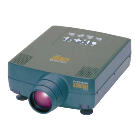
Proxima Ultralight SV1 Service Manual
Module level
Hide thumbs
Also See for Ultralight SV1:
- Technical and functional specifications (1 page) ,
- User manual (19 pages)
Summary of Contents for Proxima Ultralight SV1
- Page 1 Ultralight SV1 MODULE LEVEL SERVICE MANUAL Technical Support Proxima ASA Horsterweg 24, 6191 RX, Beek, The Netherlands Tel: +31 43 358 5210 Fax: +31 43 358 5202...
-
Page 2: Table Of Contents
MODULE LEVEL Ultralight SV1 101.670 SERVICE MANUAL 1 TABLE OF CONTENTS TABLE OF CONTENTS .........................2 REVISION HISTORY ..........................2 SCOPE ..............................3 MODULE LEVEL SERVICE AGREEMENT ...................3 ASSOCIATED DOCUMENTATION .......................3 REPLACEMENT OF MODULE LEVEL ELEMENTS ................4 SAFETY GUIDELINES........................4 PROTECTIVE CLOTHING......................4 TOOLS ............................4 TROUBLESHOOTING ...........................5... -
Page 3: Scope
MODULE LEVEL Ultralight SV1 101.670 SERVICE MANUAL 3 SCOPE This document describes the assembly of the SVGA LCD Projector unit at module level detail, and serves as a guide for the replacement of such elements when the unit needs servicing. The document does not assist in repairing the elements themselves (such as replacing individual components on the electronic circuit boards). -
Page 4: Replacement Of Module Level Elements
MODULE LEVEL Ultralight SV1 101.670 SERVICE MANUAL REPLACEMENT OF MODULE LEVEL ELEMENTS The following procedures must only be carried out by qualified and experienced service personnel authorized by means of the Module Level Service Agreement to perform module level repairs on LCD projector units. -
Page 5: Troubleshooting
MODULE LEVEL Ultralight SV1 101.670 SERVICE MANUAL 7 TROUBLESHOOTING This troubleshooting guide helps determining what parts to replace if a defective projector comes in for service. Not all possible defects are described here, only the ones that are most likely to appear. - Page 6 MODULE LEVEL Ultralight SV1 101.670 SERVICE MANUAL ROBLEM ROBABLE AUSE EMEDY Excessive fan noise Main fan(s) defective 1. Replace defective fan(s)/fanhouse 1. Fan defective complete 2. Fan mount out of position 2. Secure fan mount Loss of power to fan(s) Fan(s) is/are inoperative 1.
- Page 7 MODULE LEVEL Ultralight SV1 101.670 SERVICE MANUAL ROBLEM ROBABLE AUSE EMEDY Fuse breaks instantly Too much current to the unit 1. Wrong fuse value inserted on the 1. Replace fuse with correct value (Schurter Type: SP 2.5A Fast 250 VAC)
-
Page 8: Work Procedures
MODULE LEVEL Ultralight SV1 101.670 SERVICE MANUAL WORK PROCEDURES The numbers in brackets ( ) refer to the exploded drawing of the module level elements. An estimate of the time required for the replacement is also given as a guide for service charges. -
Page 9: Replacement Of Mechanical And Electronic Parts
MODULE LEVEL Ultralight SV1 101.670 SERVICE MANUAL 7.1.2 REPLACEMENT OF MECHANICAL AND ELECTRONIC PARTS All replacement operations require that the unit is opened; an open unit is therefore assumed in the following replacement procedures. The numbers in the left column and in the text refers to the exploded view illustration. - Page 10 MODULE LEVEL Ultralight SV1 101.670 SERVICE MANUAL REPLACEMENT OF MECHANICAL AND ELECTRONIC PARTS TASK PROCEDURE TIME REQ. MAIN PCB Neither the Polysilicone engine nor the main PCB controller CONTROLLER are available as spare parts. If malfunction, please return the complete engine including the main PCB controller for repair .
- Page 11 MODULE LEVEL Ultralight SV1 101.670 SERVICE MANUAL REPLACEMENT OF MECHANICAL AND ELECTRONIC PARTS TASK PROCEDURE TIME REQ. • Remove main PCB controller as described above. MAINS FILTER 5 min. • Remove the Polysilicon engine as described above. • Release the snapon connector on the mains filter •...
-
Page 12: Wiring Connection Diagram, Top And Bottom Cabinet
MODULE LEVEL Ultralight SV1 101.670 SERVICE MANUAL 8 WIRING CONNECTION DIAGRAM, TOP AND BOTTOM CABINET Proxima ASA CONFIDENTIAL...


