Table of Contents
Advertisement
Quick Links
Advertisement
Table of Contents

Related Manuals for ABB ACS880-204LC


Summary of Contents for ABB ACS880-204LC
- Page 1 — ABB INDUSTRIAL DRIVES ACS880-204LC IGBT supply modules Hardware manual...
- Page 3 ACS880-204LC IGBT supply modules Hardware manual Table of contents 5. Electrical installation 7. Start-up © 2019 ABB Oy. All Rights Reserved. 3AXD50000284436 Rev A EFFECTIVE: 2019-06-30...
-
Page 5: Table Of Contents
Table of contents 5 Table of contents 1 Introduction to the manual Contents of this chapter ................Applicability ..................Safety instructions ................Target audience ................... Categorization by frame size and option code ..........Use of component designations ..............Terms and abbreviations ................. Related documents ................ - Page 6 6 Table of contents 3 Moving and unpacking the module Contents of this chapter ................Moving and unpacking the module ............. 4 Cabinet construction Contents of this chapter ................Limitation of liability ................Switching, disconnecting and protecting solution ..........Frame R8i ..................Cabinet temperature supervision ...............
-
Page 7: Table Of Contents
Table of contents 7 Stage 3: Flat-PLS support kit for AC and common AC connection busbars ..Stage 4: Fan, heat exchanger and cooling components ......Stage 5A: Installation of DC busbars ........... Stage 5B: Installation of DC switch, DC connection and common mode filter busbar kits .................. - Page 8 8 Table of contents Connection procedure ................ Connecting the LCL filter ................ Main breaker / contactor ................. Installing the charging circuit ..............Connecting the external power supply cable for the auxiliary circuit ...... Connecting the control cables ..............Connection diagram ................Connection procedure ................
- Page 9 Table of contents 9 9 Ordering information Contents of this chapter ................Kit code key ..................Frame R8i and multiples ................. IGBT supply modules ................. LCL filters ..................Control panel ................... Control electronics ................Control unit .................. Fiber optic cables ................Auxiliary measurement unit (BAMU) ............
- Page 10 10 Table of contents 10 Internal cooling circuit Contents of this chapter ................Applicability ..................Internal cooling system ................Connection to a cooling unit ..............Connection to an ACS880-1007LC cooling unit .......... Connection to a custom cooling unit ............General requirements ..............Coolant temperature control .............
- Page 11 Table of contents 11 Ambient conditions ................Cooling ..................... Materials ................... Internal cooling circuit ................ Auxiliary circuit current consumption ............Control equipment ................Cooling fans ..................Definitions ..................Standards and markings ................. Disclaimers ..................Generic disclaimer ................Cybersecurity disclaimer ..............12 Control units of the drive Contents of this chapter ................
- Page 12 12 Table of contents Contents of example circuit diagrams ............ACS880-204LC IGBT supply unit 2×R8i (3AXD10000695767) ......ACS880-204LC IGBT supply unit 4×R8i (3AXD10000695768) ......Frame 2×R8i ..................Frame 4×R8i ..................Further information...
-
Page 13: Introduction To The Manual
Introduction to the manual Contents of this chapter This chapter gives basic information on the manual. Applicability The manual is applicable to the ACS880-204LC liquid-cooled IGBT supply modules for user-defined cabinet installations. Safety instructions Follow all safety instructions delivered with the drive. -
Page 14: Categorization By Frame Size And Option Code
The module size can be identified from the basic code visible on the type designation label, for example, “ACS880-204LC-0400A-7”, where 0400A is the module size. The option codes of the module are listed after a plus sign. Chapter Ordering information, section Frame R8i and multiples explains the type designation code in detail. -
Page 15: Related Documents
BCU-02/12/22 control units hardware manual 3AUA0000113605 CIO-01 I/O module for distributed I/O bus control user's manual 3AXD50000126880 Supply module manuals ACS880-204LC IGBT supply modules hardware manual 3AXD50000284436 ACS880 IGBT supply control program firmware manual 3AUA0000131562 ACS880 multidrives, Optimal grid control (option +N8053) supplement... -
Page 17: Operation Principle And Hardware Description
Contents of this chapter This chapter describes how the IGBT supply unit works and the hardware of the ACS880-204LC IGBT supply module. Operation principle IGBT supply unit rectifies three-phase AC current to direct current for the intermediate DC link of the drive. The intermediate DC link supplies the inverters that run the motors. There can be one inverter unit only (single drives) or several inverter units (multidrives) connected to the intermediate circuit. -
Page 18: Simplified Main Circuit Diagram
The control program has a function for controlling the charging circuit. For further information, see the firmware manual. ACS880-204LC contains two charging circuits: AC-DC charging circuit charges the cabinet line-up, and DC-DC charging circuit charges the DC capacitors of one cubicle. -
Page 19: Overview Diagram Of The Drive System
Operation principle and hardware description 19 Overview diagram of the drive system The following figure shows a simplified diagram of a common DC bus drive system. AC supply Input AC fuses LCL filter IGBT supply unit Supply unit DC fuses DC bus Inverter DC fuses (with or without DC switch-disconnector) Inverter units (in the example, one of the two units consists of two inverter modules connected in parallel) -
Page 20: Single-Line Circuit Diagrams Of The Supply Unit
The following figures are examples of possible IGBT supply unit configurations. The tables give explanations for the numbers and letters of the diagrams. They also indicate if the customer can order the components from ABB or if the customer needs to acquire them separately. For components, see the chapter Ordering information. -
Page 21: Frame R8I Multiples
Operation principle and hardware description 21 ■ Frame R8i multiples The following figure shows a connection example of a supply unit with multiple frame R8i modules (3×R8i). AC supply Incoming cubicle Main circuit breaker AC-DC charging kit (line-up charging) DC switch-disconnector for line-up charging LCL filter cubicles AC fuses LCL filter kit... -
Page 22: Igbt Supply Module Hardware
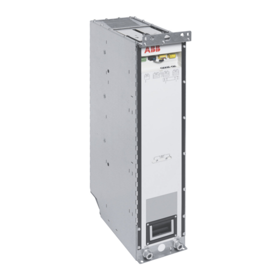
22 Operation principle and hardware description IGBT supply module hardware ■ Frame R8i hardware Module layout DC connection busbars, + (a) and - (b) Lifting eyes, front (a) and back (b) Coolant in (a) and out (b) connectors Handle Fiber optic connectors Quick connector (AC connection) (the counterpart fastened to the cabinet behind the module) Terminal block X50 (auxiliary power input for internal boards) Terminal block X51 and X52 (Safe torque off in inverter modules only) -
Page 23: Coolant Connectors
Operation principle and hardware description 23 Coolant connectors The coolant pipe inlet and outlet connectors are located at the bottom front of the module. The connectors are for 16/13 millimeter PA (polyamide) pipe. Connectors X50…X59 R8i modules contain a power supply (BDPS) that provides 24 V DC for the circuit boards of the module. -
Page 24: Fiber Optic Connectors
24 Operation principle and hardware description AC IN Auxiliary voltage inputs for internal power supply (BDPS) 24V OUT 24 V DC output (for eg. BCU control unit) STO IN STO connectors of the module. Must be connected to 24 V DC for the supply module to start. -
Page 25: Control Interfaces
Operation principle and hardware description 25 Control interfaces ■ BCU control unit of frame R8i and multiples Frame R8i (and multiples, if any) modules are controlled by a single BCU control unit installed separately from the module(s). The control unit is connected to each module by a fiber optic link. -
Page 26: Overview Of The Control Connections Of The Bcu Control Unit
26 Operation principle and hardware description ■ Overview of the control connections of the BCU control unit The diagram shows the control connections and interfaces of the BCU control unit. Analog and digital I/O extension modules and Control panel. fieldbus communication modules can be inserted into slots 1, 2 and 3. -
Page 27: Supply Unit Control Devices
Operation principle and hardware description 27 Supply unit control devices ■ Main disconnecting device The unit must be equipped with a main circuit breaker [Q1]. With this device, you can isolate the main circuit of the drive from the power line. WARNING! The breaker does not isolate the input power terminals or the auxiliary circuit from the power line. -
Page 28: Line-Up Charging Switch
28 Operation principle and hardware description To change between local and remote control mode, press the Loc/Rem key of the control panel. For the instructions on the use of the panel, see ACX-AP-x Assistant control panels user's manual (3AUA0000085685 [English]). For the parameter settings, see the firmware manual. -
Page 29: Pc Connection
Operation principle and hardware description 29 ■ PC connection There is a USB connector on the front of the control panel that can be used to connect a PC to the drive. When a PC is connected to the control panel, the control panel keypad is disabled. -
Page 30: Type Designation Key
IGBT supply module Type designation describes the composition of the module in short. Note that in the type designation label of an IGBT supply module (ACS880-204LC), the type of the module is ACS880-104LC. The complete designation code is divided in subcodes: •... -
Page 31: Moving And Unpacking The Module
Moving and unpacking the module 31 Moving and unpacking the module Contents of this chapter This chapter gives basic information on unpacking and moving the module. WARNING! For the safety instructions, see Safety instructions for ACS880 liquid-cooled multidrive cabinets and modules (3AXD50000048633 [English]). Moving and unpacking the module The modules are delivered on a wooden base, boxed in corrugated cardboard. -
Page 33: Cabinet Construction
The installation must always be designed and made according to applicable local laws and regulations. ABB does not assume any liability whatsoever for any installation which breaches the local laws and/or other regulations. Furthermore, if the recommendations given by ABB are not followed, the drive may experience problems that the warranty does not cover. -
Page 34: Cabinet Temperature Supervision
DC busbar above the AC fuses [F6.10] and below the LCL filter capacitors [F6.11]. ABB recommends to use thermal switch with 110 °C (230 °F) temperature limit for the AC fuses and thermal switch with 70 °C (158 °F) temperature limit for the LCL filter capacitors. -
Page 35: Installation Examples
You can find the kit-specific assembly drawings, step-by-step instructions and kit information on the Internet. Go to https://sites-apps.abb.com/sites/lvacdrivesengineeringsupport/content. If needed, contact your local ABB representative. The example includes also cabinet assembly drawings that show each stage listed in the table. More detailed steps of each stage are described in the kit-specific assembly drawings. -
Page 36: Blcl-15Lc-7 / Blcl-24Lc-7 In A 600 Mm Wide Rittal Vx25 Enclosure
36 Cabinet construction ■ BLCL-15LC-7 / BLCL-24LC-7 in a 600 mm wide Rittal VX25 enclosure Layout drawing Below is an example layout of an LCL filter. Description AC connection from incoming cabinet (Rittal Flat-PLS) AC fuses Grid-side choke (behind the capacitors) Capacitors (amount varies depending on the LCL filter size) Connection to capacitors by cables... -
Page 37: Pipe Routing Example (Blcl-15Lc-7)
Cabinet construction 37 Pipe routing example (BLCL-15LC-7) Description Coolant in Inlet manifold with stop and drain valves Heat exchanger Outlet manifold with stop and drain valves Coolant out Thicker pipe is of type 16/13 and thinner pipe of type 8/6. Pipe routing example (BLCL-24LC-7 and BLCL-25LC-7) Description Coolant in... -
Page 38: Installation Stages
38 Cabinet construction Installation stages Installation stage Instruction code Kit code Kit ordering code Cabinet floor Common DC bus 3AXD50000333639 A-468-X-001-VX 3AXD50000333387 Marine support kit L-6-8-500-VX 3AXD50000457885 3AXD50000429653 L-468-8-314-VX 3AXD50000426652 LCL side plates and common AC bus 3AXD50000245987 L-6-X-012 3AXD50000237371 Brackets for Flat-PLS holder installa- 3AXD50000370870 L-6-X-012-VX... -
Page 39: Overview Of Kits
Cabinet construction 39 Overview of kits... -
Page 40: Stage 1: Installation Of Common Parts
40 Cabinet construction Stage 1: Installation of common parts... -
Page 41: Stage 2: Installation Of Lcl Side Plates And Common Ac Bus
Cabinet construction 41 Stage 2: Installation of LCL side plates and common AC bus... -
Page 42: Stage 3: Installation Of Brackets For Flat-Pls Holder
42 Cabinet construction Stage 3: Installation of brackets for Flat-PLS holder... -
Page 43: Stage 4A: Blcl-15Lc-7: Ac Connection And Fuse Busbars Installation
Cabinet construction 43 Stage 4A: BLCL-15LC-7: AC connection and fuse busbars installation... -
Page 44: Stage 4B: Blcl-24Lc-7: Ac Connection And Fuse Busbars Installation
44 Cabinet construction Stage 4B: BLCL-24LC-7: AC connection and fuse busbars installation... -
Page 45: Stage 5: Installation Of Lcl Choke Mounting Mechanics And Lcl Isu Connection
Cabinet construction 45 Stage 5: Installation of LCL choke mounting mechanics and LCL ISU connection... -
Page 46: Stage 6: Lcl Choke And Lcl Choke Busbar Installation
46 Cabinet construction Stage 6: LCL choke and LCL choke busbar installation... -
Page 47: Stage 7: Heat Exchanger, Heat Exchanger Mechanics And Cooling Components
Cabinet construction 47 Stage 7: Heat exchanger, heat exchanger mechanics and cooling components installation... -
Page 48: Stage 8A: Blcl-15Lc-7: Lcl Capacitor Support, Fan Support Mechanics And Fan Installation
48 Cabinet construction Stage 8A: BLCL-15LC-7: LCL capacitor support, fan support mechanics and fan installation... -
Page 49: Stage 8B: Blcl-24Lc-7: Lcl Capacitor Support, Fan Support Mechanics And Fan Installation
Cabinet construction 49 Stage 8B: BLCL-24LC-7: LCL capacitor support, fan support mechanics and fan installation... -
Page 50: Stage 9: Installation Of Lcl Shroud Kit
50 Cabinet construction Stage 9: Installation of LCL shroud kit... -
Page 51: Blcl-25Lc-7 In A 600 Mm Wide Rittal Vx25 Enclosure
Cabinet construction 51 ■ BLCL-25LC-7 in a 600 mm wide Rittal VX25 enclosure Installation stages Installation stage Instruction code Kit code Kit ordering code Cabinet floor Common DC bus 3AXD50000333639 A-468-X-001-VX 3AXD50000333387 Marine support kit L-6-8-500-VX 3AXD50000457885 3AXD50000429653 L-468-8-314-VX 3AXD50000426652 LCL side plates and common AC bus 3AXD50000245987 L-6-X-012... -
Page 52: Overview Of Kits
52 Cabinet construction Overview of kits... -
Page 53: Stage 1: Installation Of Common Parts
Cabinet construction 53 Stage 1: Installation of common parts... -
Page 54: Stage 2: Installation Of Lcl Side Plates And Common Ac Bus
54 Cabinet construction Stage 2: Installation of LCL side plates and common AC bus... -
Page 55: Stage 3: Installation Of Brackets For Flat-Pls Holder
Cabinet construction 55 Stage 3: Installation of brackets for Flat-PLS holder... -
Page 56: Stage 4: Ac Connection And Fuse Busbars Installation
56 Cabinet construction Stage 4: AC connection and fuse busbars installation... -
Page 57: Stage 5: Installation Of Lcl Choke Mounting Mechanics And Lcl Isu Connection
Cabinet construction 57 Stage 5: Installation of LCL choke mounting mechanics and LCL ISU connection... -
Page 58: Stage 6: Lcl Choke And Lcl Choke Busbar Installation
58 Cabinet construction Stage 6: LCL choke and LCL choke busbar installation... -
Page 59: Stage 7: Heat Exchanger, Heat Exchanger Mechanics And Cooling Components
Cabinet construction 59 Stage 7: Heat exchanger, heat exchanger mechanics and cooling components installation... -
Page 60: Stage 8: Lcl Capacitor Support, Fan Support Mechanics And Fan Installation
60 Cabinet construction Stage 8: LCL capacitor support, fan support mechanics and fan installation... -
Page 61: Stage 9: Installation Of Lcl Shroud Kit
Cabinet construction 61 Stage 9: Installation of LCL shroud kit... -
Page 62: One R8I Module In A 400 Mm Wide Rittal Vx25 Enclosure
62 Cabinet construction ■ One R8i module in a 400 mm wide Rittal VX25 enclosure Layout drawing Description Common DC busbars (Rittal Flat-PLS) DC fuses and optional DC switch Common mode filter IGBT supply module Heat exchanger Cooling fan AC connection to LCL filter (Rittal Flat-PLS) Inlet and outlet manifold with valves... -
Page 63: Pipe Routing Example
Cabinet construction 63 Pipe routing example Description Coolant in Inlet manifold with stop and drain valves Heat exchanger IGBT supply module Outlet manifold with stop and drain valves Coolant out... -
Page 64: Installation Stages
64 Cabinet construction Installation stages Installation stage Instruction code Kit code Kit ordering code Baying parts 3AXD50000336340 DC bus 3AXD50000333639 A-468-X-001-VX 3AXD50000333387 3AXD50000327591 L-468-8-020-VX 3AXD50000360543 Side plate, module mounting mech- 3AXD50000330461 L-4-8-301-VX 3AXD50000360598 anics and quick connectors 3AUA0000118667 A-468-8-100 3AUA0000119227 3AXD50000370870 L-468-X-012-VX 3AXD50000371013... -
Page 65: Overview Of Kits
Cabinet construction 65 Overview of kits... -
Page 66: Stage 1: Installation Of Common Parts
66 Cabinet construction Stage 1: Installation of common parts... -
Page 67: Stage 2: Side Plate, Module Mounting Mechanics And Quick Connectors
Cabinet construction 67 Stage 2: Side plate, module mounting mechanics and quick connectors... -
Page 68: Stage 3: Flat-Pls Support Kit For Ac And Common Ac Connection Busbars
68 Cabinet construction Stage 3: Flat-PLS support kit for AC and common AC connection busbars... -
Page 69: Stage 4: Fan, Heat Exchanger And Cooling Components
Cabinet construction 69 Stage 4: Fan, heat exchanger and cooling components... -
Page 70: Stage 5A: Installation Of Dc Busbars
70 Cabinet construction Stage 5A: Installation of DC busbars... -
Page 71: Stage 5B: Installation Of Dc Switch, Dc Connection And Common Mode Filter Busbar Kits
Cabinet construction 71 Stage 5B: Installation of DC switch, DC connection and common mode filter busbar kits... -
Page 72: Stage 6: Module Installation
72 Cabinet construction Stage 6: Module installation... -
Page 73: Stage 7: Installation Of Shrouding
Cabinet construction 73 Stage 7: Installation of shrouding... -
Page 74: Two R8I Modules In A 600 Mm Wide Rittal Vx25 Enclosure
74 Cabinet construction ■ Two R8i modules in a 600 mm wide Rittal VX25 enclosure Layout drawing Description Common DC busbars (Rittal Flat-PLS) DC fuses and optional DC switch Common mode filter IGBT supply module Heat exchanger Cooling fan AC connection to LCL filter (Rittal Flat-PLS) Inlet and outlet manifold with valves... -
Page 75: Pipe Routing Example
Cabinet construction 75 Pipe routing example Description Coolant in Inlet manifold with stop and drain valves Heat exchanger IGBT supply module Outlet manifold with stop and drain valves Coolant out... -
Page 76: Installation Stages
76 Cabinet construction Installation stages Installation stage Instruction code Kit code Kit ordering code Baying parts 3AXD50000336340 DC bus 3AXD50000333639 A-468-X-001-VX 3AXD50000333387 3AXD50000327591 L-468-8-020-VX 3AXD50000360543 Side plate, module mounting mech- 3AXD50000330201 L-6-8-302-VX 3AXD50000361090 anics and quick connectors 3AUA0000118667 A-468-8-100 3AUA0000119227 3AXD50000370870 L-468-X-012-VX 3AXD50000371013... -
Page 77: Overview Of Kits
Cabinet construction 77 Overview of kits... -
Page 78: Stage 1: Installation Of Common Parts
78 Cabinet construction Stage 1: Installation of common parts... -
Page 79: Stage 2: Side Plate, Module Mounting Mechanics And Quick Connectors
Cabinet construction 79 Stage 2: Side plate, module mounting mechanics and quick connectors... -
Page 80: Stage 3: Flat-Pls Support Kit For Ac And Common Ac Connection Busbars
80 Cabinet construction Stage 3: Flat-PLS support kit for AC and common AC connection busbars... -
Page 81: Stage 4: Fan, Heat Exchanger And Cooling Components
Cabinet construction 81 Stage 4: Fan, heat exchanger and cooling components... -
Page 82: Stage 5A: Installation Of Dc Busbars
82 Cabinet construction Stage 5A: Installation of DC busbars... -
Page 83: Stage 5B: Installation Of Dc Switch, Dc Connection And Common Mode Filter Busbar Kits
Cabinet construction 83 Stage 5B: Installation of DC switch, DC connection and common mode filter busbar kits... -
Page 84: Stage 6: Module Installation
84 Cabinet construction Stage 6: Module installation... -
Page 85: Stage 7: Installation Of Shrouding
Cabinet construction 85 Stage 7: Installation of shrouding... -
Page 86: Three R8I Modules In A 800 Mm Wide Rittal Vx25 Enclosure
86 Cabinet construction ■ Three R8i modules in a 800 mm wide Rittal VX25 enclosure Layout drawing Description Common DC busbars (Rittal Flat-PLS) DC fuses and optional DC switch Common mode filter IGBT supply module Heat exchanger Cooling fan AC connection to LCL filter (Rittal Flat- PLS) Inlet and outlet manifold with valves... -
Page 87: Pipe Routing Example
Cabinet construction 87 Pipe routing example Description Coolant in Inlet manifold with stop and drain valves Heat exchanger IGBT supply module Outlet manifold with stop and drain valves Coolant out... -
Page 88: Installation Stages
88 Cabinet construction Installation stages Installation stage Instruction code Kit code Kit ordering code Baying parts 3AXD50000336340 DC bus 3AXD50000333639 A-468-X-001-VX 3AXD50000333387 3AXD50000327591 L-468-8-020-VX 3AXD50000360543 Side plate, module mounting mech- 3AXD50000329502 L-8-8-303-VX 3AXD50000361274 anics and quick connectors 3AUA0000118667 A-468-8-100 3AUA0000119227 3AXD50000370870 L-468-X-012-VX 3AXD50000371013... -
Page 89: Overview Of Kits
Cabinet construction 89 Overview of kits... -
Page 90: Stage 1: Installation Of Common Parts
90 Cabinet construction Stage 1: Installation of common parts... -
Page 91: Stage 2: Side Plate, Module Mounting Mechanics And Quick Connectors
Cabinet construction 91 Stage 2: Side plate, module mounting mechanics and quick connectors... -
Page 92: Stage 3: Flat-Pls Support Kit For Ac And Common Ac Connection Busbars
92 Cabinet construction Stage 3: Flat-PLS support kit for AC and common AC connection busbars... -
Page 93: Stage 4: Fan, Heat Exchanger And Cooling Components
Cabinet construction 93 Stage 4: Fan, heat exchanger and cooling components... -
Page 94: Stage 5A: Installation Of Dc Busbars
94 Cabinet construction Stage 5A: Installation of DC busbars... -
Page 95: Stage 5B: Installation Of Dc Switch, Dc Connection And Common Mode Filter Busbar Kits
Cabinet construction 95 Stage 5B: Installation of DC switch, DC connection and common mode filter busbar kits... -
Page 96: Stage 6: Module Installation
96 Cabinet construction Stage 6: Module installation... -
Page 97: Stage 7: Installation Of Shrouding
Cabinet construction 97 Stage 7: Installation of shrouding... -
Page 99: Electrical Installation
The installation must always be designed and made according to applicable local laws and regulations. ABB does not assume any liability whatsoever for any installation which breaches the local laws and/or other regulations. Furthermore, if the recommendations given by ABB are not followed, the drive system may experience problems that the warranty does not cover. -
Page 100: Electrical Safety Precautions
100 Electrical installation Electrical safety precautions These electrical safety precautions are for all personnel who do work on the drive, motor cable or motor. WARNING! Obey these instructions. If you ignore them, injury or death, or damage to the equipment can occur. If you are not a qualified electrician, do not do installation or maintenance work. -
Page 101: Isolation From Ac Supply Networks
Electrical installation 101 7. Install temporary grounding as required by the local regulations. 8. Ask the person in control of the electrical installation work for a permit to work. WARNING! In case of DC bus remaining alive, Personal Protective Equipment (PPE) of Level 2 is required for doing maintenance. -
Page 102: Isolation From Common Dc Bus
102 Electrical installation Isolation from common DC bus In case of units with DC voltage remaining: if there are several power sources for the DC bus, the supply unit which shall be isolated must be equipped with a DC switch-disconnector. In order to isolate the supply unit from the live DC bus, open the DC switch-disconnector [Q11] and also the charging switch [Q10] in EVERY cubicle containing supply modules. -
Page 103: Checking The Insulation Of The Assembly
The RFI filter is not suitable for use in IT (ungrounded) systems. Disconnect the filter before connecting the drive to the supply network. For instructions on how to do this, contact your local ABB representative. WARNING! If a drive with an RFI filter is installed on an IT system (an ungrounded power system), the system will be connected to earth potential through the filter capacitors of the drive. -
Page 104: Connecting The Input Power Cables/Busbars
104 Electrical installation Connecting the input power cables/busbars ■ Connection diagram Components for main charging circuit. For details, see chapter Example circuit diagrams. Components for DC charging circuit. For details, see chapter Example circuit diagrams. Incoming cubicle LCL filter cubicle IGBT supply module cubicle Notes: For the conductivity requirements for the shield and the PE conductor, see ACS880... -
Page 105: Connection Procedure For Power Connections Inside The Igbt Supply Module Cubicle
Electrical installation 105 ■ Connection procedure for power connections inside the IGBT supply module cubicle For the cable types, see Electrical planning instructions for ACS880 multidrive cabinets and modules (3AXD50000048634 [English]). WARNING! Obey the safety instructions given in Safety instructions for ACS880 liquid-cooled multidrive cabinets and modules (3AXD50000048633 [English]). -
Page 106: Connection Procedure
106 Electrical installation 5. Refit any shrouding removed earlier and close the cubicle doors. ■ Connection procedure WARNING! Obey the safety instructions given in Safety instructions for ACS880 liquid-cooled multidrive cabinets and modules (3AXD50000048633 [English]). If you ignore the safety instructions, injury or death, or damage to the equipment can occur. - Page 107 PE (ground) busbar. 10. Connect the phase conductors of the charging circuit supply cable to the charging circuit. The connections of the ABB-defined charging circuit with the terminal markings are shown in example circuit diagrams. See the tightening torques in technical data.
-
Page 108: Connecting The Lcl Filter
If the overheating protection is removed with parameter settings, the filter may be damaged permanently or cause a fire. WARNING! Use the LCL filter only with an ACS880-204LC IGBT supply module. Use the filter only with an IGBT supply module of an appropriate frame size. -
Page 109: Main Breaker / Contactor
Example circuit diagrams. Consult ABB for more information on the components and wirings needed. Note that ACS880-204LC contains two separate charging circuits: AC-DC charging circuit (line-up charging) and DC-DC charging circuit. Activate and tune the charging function in the control program. For information on tuning the parameters, see ACS880 IGBT supply control program firmware manual [3AUA0000131562 (English)]. -
Page 110: Connecting The Control Cables
110 Electrical installation Connecting the control cables ■ Connection diagram See the example circuit diagrams, and the default I/O diagram. ■ Connection procedure Note: The instructions below are based on an example cabinet construction. They are not applicable to all possible solutions but only clarify the principles. The following procedure instructs how to connect the control cables of a supply unit. -
Page 111: Connectors X50
Electrical installation 111 6. Strip the cable ends and conductors. When connecting to the drive I/O, also remove the shield along with the outer sheathing, and use electrical tape or shrink tubing to contain the strands. Elsewhere, twist outer shield strands into a bundle, crimp a lug onto it and connect it to the nearest chassis grounding point. -
Page 112: Connecting A Pc
112 Electrical installation Connecting a PC A PC (with eg, the Drive composer PC tool) can be connected as follows: 1. Connect an ACx-AP-x control panel to the unit either • by inserting the control panel into the panel holder or platform (if present), or •... -
Page 113: Installing Optional Modules
Electrical installation 113 Installing optional modules WARNING! Obey the safety instructions of the drive. If you ignore them, injury or death, or damage to the equipment can occur. Note: Pay attention to the free space required by the cabling or terminals coming to the optional modules. -
Page 115: Installation Checklist Of The Drive
Installation checklist of the drive 115 Installation checklist of the drive Contents of this chapter This chapter contains a checklist of the mechanical and electrical installation of the drive. Checklist Examine the mechanical and electrical installation of the drive before start-up. Go through the checklist together with another person. - Page 116 116 Installation checklist of the drive Make sure that … The main circuit connections inside the drive cabinet correspond to the circuit diagrams. The control unit has been connected. See the circuit diagrams. Appropriate AC fuses and main disconnector have been installed. There is an adequately sized protective earth (ground) conductor between the drive and the switchboard, the conductor has been connected to appropriate terminal, and the terminal has been tightened to the proper torque.
-
Page 117: Start-Up
Contents of this chapter This chapter instructs how to start up the IGBT supply unit. The instructions are valid for the example IGBT supply unit with ACS880-204LC IGBT supply modules. The default device designations (if any) are given in square brackets, for example, main circuit breaker [Q1]. -
Page 118: Start-Up Procedure
118 Start-up Start-up procedure Tasks Safety WARNING! Obey the safety instructions during the start-up procedure. See Safety instructions for ACS880 liquid-cooled multidrive cabinets and modules (3AXD50000048633 [English]). Only qualified electricians are allowed to start-up the drive. Checks/Settings with no voltage connected WARNING! Ensure that the disconnector of the supply transformer is locked to the off (0) position, that means no voltage is, or can not be, connected to drive inadvertently. - Page 119 Start-up 119 Tasks Starting and checking the cooling system Fill up and bleed the internal cooling circuit. Start the cooling unit up. See section Filling up and bleeding the internal cooling circuit (page 174). Check the cooling system for leaks. Make sure that cooling circuit joints at the shipping split joining cubicles are tight and that all drain valves have been closed.
-
Page 120: Switching The Supply Unit Off
120 Start-up Tasks Validate the operation of safety functions (for example, emergency stop). WARNING! The safety functions are not safe before they are validated according to the instructions. Safety functions are optional. See the function-specific manual for the validation tasks. Switching the supply unit off 1. -
Page 121: Maintenance
Contents of this chapter This chapter instructs how to maintain the IGBT supply module and how to interpret its fault conditions. The information is valid for ACS880-204LC IGBT supply modules and the cabinet construction examples presented in this manual. WARNING! Only qualified electricians are allowed to do the work described in this chapter. - Page 122 Performance of on/off-site work (commissioning, tests, measurements or other work) Replacement Maintenance and component replacement intervals are based on the assumption that the equipment is operated within the specified ratings and ambient conditions. ABB recommends annual drive inspections to ensure the highest reliability and optimum performance.
-
Page 123: Maintenance Timers And Counters
Maintenance 123 Note: Long term operation near the specified maximum ratings or ambient conditions may require shorter maintenance intervals for certain components. Consult your local ABB Service representative for additional maintenance recommendations. Maintenance timers and counters The control program has maintenance timers and counters that can be configured to generate a warning when a pre-defined limit is reached. -
Page 124: Power Connections
See the firmware manual for the actual signal which indicates the running time of the cooling fan. Reset the running time signal after fan replacement. Replacement fans are available from ABB. Do not use other than ABB specified spare parts. ■... - Page 125 Maintenance 125...
-
Page 126: Replacing The Cooling Fan Of The Lcl Filter
126 Maintenance ■ Replacing the cooling fan of the LCL filter WARNING! Wear protective gloves and long sleeves. Some parts have sharp edges. 1. Repeat the steps described in section Electrical safety precautions (page 100). 2. Remove any shrouding in front of the cooling fan. 3. -
Page 127: Igbt Supply Module
Maintenance 127 IGBT supply module ■ Replacing the IGBT supply module (frame R8i) WARNING! Obey the safety instructions given in Safety instructions for ACS880 liquid-cooled multidrive cabinets and modules (3AXD50000048633 [English]). If you ignore the safety instructions, injury or death, or damage to the equipment can occur. - Page 128 128 Maintenance 6. Close the inlet valve (a) and outlet valve (located on the right-hand side of the cubicle) valves. Lead the drain hoses (b, on both sides of the cubicle) into a suitable container. Open the drain valves (c, on both sides of the cubicle). This will drain all modules in the cubicle.
-
Page 129: Reinstalling The Module
Maintenance 129 9. Pull the module carefully out onto a table or other platform. Keep the module secured to a hoist or equivalent to prevent the module from falling. For information on using the lifting device, see Converter module lifting device for drive cabinets hardware manual (3AXD50000210268 [English]). -
Page 130: Capacitors
Capacitor failure is usually followed by damage to the unit and an input cable fuse failure, or a fault trip. Contact ABB if capacitor failure is suspected. Replacements are available from ABB. Do not use other than ABB specified spare parts. Contact an ABB service representative for spare parts and repair services. -
Page 131: Replacing The Bcu Control Unit Battery
Maintenance 131 ■ Replacing the BCU control unit battery Replace the real-time clock battery if the BATT OK LED is not illuminated when the control unit is powered. 1. Stop the drive and do the steps in section Electrical safety precautions (page 100) before you start the work. -
Page 132: R8I Module Leds
132 Maintenance Location Indication Control panel Continuous green The unit is functioning normally. Flickering green Data is transferred between the PC and the unit through the USB connection of the control panel. Blinking green There is an active warning in the unit. Continuous red There is an active fault in the unit. -
Page 133: Ordering Information
Note: • This chapter only lists the installation accessories available from ABB. All other parts must be sourced from a third party (such as Rittal) by the system integrator. For a listing, refer to the kit-specific installation instructions available at https://sites-apps.abb.com/sites/lvacdrivesengineeringsupport/content. -
Page 134: Kit Code Key
134 Ordering information Kit code key The kit codes shown in this chapter break down as follows. The format of the kit code is x-w-s-yyy(-VX), for example, L-6-8-401 where: • x = cooling method • A = air-cooled (some of these kits are also used with liquid-cooled drives) •... -
Page 135: Frame R8I And Multiples
IGBT supply units consisting of frame R8i IGBT supply modules are to be ordered as separate modules. IGBT supply unit Modules used Type Frame size Ordering code (for options see below) = 690 V ACS880-204LC-0360A-7 ACS880-104LC-0390A-7+E205 ACS880-204LC-0400A-7 ACS880-104LC-0430A-7+E205 ACS880-204LC-0450A-7 ACS880-104LC-0480A-7+E205 ACS880-204LC-0480A-7 ACS880-104LC-0530A-7+E205 ACS880-204LC-0560A-7... -
Page 136: Lcl Filters
LCL filter delivery contains LCL filter components as loose parts. LCL filter contains the grid-side choke, converter-side choke, capacitors and resistor. For contents, see Kit contents of the LCL filters. LCL filter ACS880-204LC-… LCL filter type Ordering code = 690 V 0360A-7 BLCL-15LC-7... -
Page 137: Control Panel
Ordering information 137 114 Ordering information ■ Control panel Control panel The control panel is not included with the module but must be ordered separately. One The control panel is not included with the supply module but must be ordered separately. control panel is required for the commissioning of an ACS880 drive system, even if the Drive One control panel is required for the commissioning of an ACS880 drive system, even if composer PC tool is used. -
Page 138: Control Electronics
Fiber optic cables Each frame R8i module is connected to the control unit with a pair of fiber optic cables. The following kits, each consisting of a pair of plastic fiber optic cables, are available from ABB: Length Kit type designation... -
Page 139: Cio-01 I/O Module
Ordering information 139 CIO-01 I/O module CIO-01 I/O module for distributed I/O bus control is not included in the module delivery but must be ordered separately. The distributed I/O bus controls and supervises each cabinet fan separately. It indicates malfunctioning fans by warning or fault messages. For more information, see CIO-01 I/O module for distributed I/O bus control (3AXD50000126880 [English]). -
Page 140: Module Top/Bottom Guides
140 Ordering information Module top/bottom guides This kit contains the frames that support the module at the top and the bottom. Used with… Ordering code Kit code Illustration 400 mm Rittal VX25 en- 3AXD50000360598 L-4-8-301-VX closure Instruction code: 3AXD50000330461 600 mm Rittal VX25 en- 3AXD50000361090 L-6-8-302-VX closure... -
Page 141: Shrouding
Ordering information 141 Shrouding This kit contains the shroud to cover the top part of the cubicle with the necessary brackets and screws. Used with… Ordering code Kit code Illustration 400 mm Rittal VX25 en- 3AXD50000361083 L-4-8-022-VX closure Instruction code: 3AXD50000353354 600 mm Rittal VX25 en- 3AXD50000361267 L-6-8-023-VX... -
Page 142: Marine Support Kit For Lcl Filters
142 Ordering information Used with… Ordering code Kit code Illustration BLCL-15LC-7, BLCL- 24LC-7 and BLCL-25LC-7 3AXD50000426638 A-6-8-027-VX (600 mm Rittal VX25 en- closure) Instruction code: 3AXD50000431632 Marine support kit for LCL filters Used with… Ordering code Kit code Illustration BLCL-15LC-7, BLCL- 24LC-7 and BLCL-25LC-7 3AXD50000457885 L-6-8-500-VX... - Page 143 Ordering information 143 IGBT supply unit Main circuit breakers (230 V, IEC) Type Type Ordering code = 690 V ACS880-204LC-0360A-7 E2.2S-A1200EKIP DIP LI 3AXD50000048328 AC220V, IEC, UL, CCC ACS880-204LC-0400A-7 E2.2S-A1200EKIP DIP LI 3AXD50000048328 AC220V, IEC, UL, CCC ACS880-204LC-0450A-7 E2.2S-A1200EKIP DIP LI...
- Page 144 144 Ordering information 1SDA073700R1 • YU E1.2..E6.2 220-240 Vac/dc 1SDA073725R1 • M E2.2..E6.2 220-250 Vac/dc 1SDA073781R1 • MOC E2.2..E6.2 1SDA073756R1 • AUX 6Q 400V E2.2..E6.2 1SDA073792R1 • KLC-S Key lock open N.20005 E2.2..E6.2 1SDA073807R1 • KLP-S Key lock racked in/out N.20005 E2.2...E6.2 1st key 1SDA083022R1 (E2.2S), •...
- Page 145 Ordering information 145 IGBT supply unit Wagons (230 V, IEC) Type Type Ordering code = 690 V ACS880-204LC-0360A-7 E2.2-A_W_FP_2000HR- 3AXD50000048354 HR_UL, IEC, CCC AUX- CONT ACS880-204LC-0400A-7 E2.2-A_W_FP_2000HR- 3AXD50000048354 HR_UL, IEC, CCC AUX- CONT ACS880-204LC-0450A-7 E2.2-A_W_FP_2000HR- 3AXD50000048354 HR_UL, IEC, CCC AUX-...
- Page 146 146 Ordering information Content of the 230 V wagons: 1SDA079698R1 (E2.2-A W FP 2000) • W FP Iu=2000 3p HR HR UL / W FP Iu=2500 3p HR HR UL / 1SDA079700R1 (E4.2-A W FP 2500) WAGON W FP Iu=5000 HR HR UL 1SDA079706R1 (E6.2-A W FP 5000) 1SDA080373R1 •...
- Page 147 Ordering information 147 IGBT supply unit Main circuit breakers (115 V, IEC) Type Type Ordering code = 690 V ACS880-204LC-0360A-7 E2.2S-A1200EKIP DIP LI 3AXD50000048351 AC110V, IEC,UL, CCC ACS880-204LC-0400A-7 E2.2S-A1200EKIP DIP LI 3AXD50000048351 AC110V, IEC,UL, CCC ACS880-204LC-0450A-7 E2.2S-A1200EKIP DIP LI 3AXD50000048351...
- Page 148 148 Ordering information 1SDA073698R1 • YU E1.2..E6.2 110-120 Vac/dc 1SDA073724R1 • M E2.2...E6.2 100-130 Vac/dc 1SDA073781R1 • MOC E2.2..E6.2 1SDA073756R1 • AUX 6Q 400V E2.2..E6.2 1SDA073792R1 • KLC-S Key lock open N.20005 E2.2..E6.2 1SDA073807R1 • KLP-S Key lock racked in/out N.20005 E2.2...E6.2 1st key 1SDA083022R1 (E2.2S), •...
- Page 149 Ordering information 149 IGBT supply unit Wagons (115 V, IEC) Type Type Ordering code = 690 V ACS880-204LC-0360A-7 E2.2-A_W_FP_2000HR- 3AXD50000048354 HR_UL, IEC, CCC AUX- CONT ACS880-204LC-0400A-7 E2.2-A_W_FP_2000HR- 3AXD50000048354 HR_UL, IEC, CCC AUX- CONT ACS880-204LC-0450A-7 E2.2-A_W_FP_2000HR- 3AXD50000048354 HR_UL, IEC, CCC AUX-...
-
Page 150: Iec Busbar Shim Kits
150 Ordering information Content of the 115 V wagons: 1SDA079698R1 (E2.2-A W FP 2000) • W FP Iu=2000 3p HR HR UL / W FP Iu=2500 3p HR HR UL / 1SDA079700R1 (E4.2-A W FP 2500) WAGON W FP Iu=5000 HR HR UL 1SDA079706R1 (E6.2-A W FP 5000) 1SDA080373R1 •... -
Page 151: Ac Fuses
Ordering information 151 AC fuses The AC fuses protect the input cables and the module against short circuits. IGBT supply AC fuses unit Type Type Ordering code = 690 V ACS880-204LC- 170M6410 68335418 0360A-7 ACS880-204LC- 170M6411 3AXD50000000175 0400A-7 ACS880-204LC- 170M6412... -
Page 152: Ac-Dc Charging Kits For Line-Up Charging
+ 4×INU) and 7 × IGBT supply unit DC capacitance (1×ISU + 6×INU). If the total DC link capacitance (including IGBT supply and inverter module DC capacitances) exceeds these limits, the components must be redimensioned. Contact ABB representative for more information. The capacitances of the IGBT supply module types and the inverter module types are specified in their technical data tables. -
Page 153: Ac Busbars For Lcl Filters
Ordering information 153 AC busbars for LCL filters Used with … Ordering code Kit code Illustration BLCL-15LC-7 (600 mm Rittal VX25 3AXD50000237470 L-6-8-108 enclosure) Instruction code: 3AXD50000248476 BLCL-24LC-7 (600 mm Rittal VX25 3AXD50000237487 L-6-8-109 enclosure) Instruction code: 3AXD50000249206 BLCL-25LC-7 (600 mm Rittal VX25 3AXD50000237494 L-6-8-110 enclosure) -
Page 154: Lcl Choke Installation Kits
154 Ordering information Used with … Ordering code Kit code Illustration BLCL-24LC-7 (600 L-6-8-104- mm Rittal VX25 en- 3AXD50000426676 closure) Instruction code: 3AXD50000431403 BLCL-25LC-7 (600 L-6-8-105- mm Rittal VX25 en- 3AXD50000426683 closure) Instruction code: 3AXD50000431724 LCL choke installation kits Used with … Ordering code Kit code Illustration... - Page 155 Ordering information 155 Used with … Ordering code Kit code Illustration BLCL-15LC-7 and BLCL-24LC-7 L-6-8-306- 3AXD50000426195 (600 mm Rittal VX25 enclosure) Instruction code: 3AXD50000431915 BLCL-25LC-7 L-6-8-307- (600 mm Rittal VX25 3AXD50000426201 enclosure) Instruction code: 3AXD50000431816 BLCL-15LC-7 and BLCL-24LC-7 3AXD50000237517 L-6-8-311 (600 mm Rittal VX25 enclosure) Instruction code: 3AXD50000249893...
-
Page 156: Lcl Capacitor Installation Kits
156 Ordering information LCL capacitor installation kits Used with … Ordering code Kit code Illustration BLCL-15LC-7 (600 mm Rittal VX25 3AXD50000237319 L-6-8-308 enclosure) Instruction code: 3AXD50000247097 BLCL-24LC-7 (600 mm Rittal VX25 3AXD50000237333 L-6-8-309 enclosure) Instruction code: 3AXD50000247097 BLCL-25LC-7 (600 mm Rittal VX25 3AXD50000237340 L-6-8-310 enclosure) -
Page 157: Lcl Isu Connection Kits
Ordering information 157 LCL ISU connection kits Used with … Ordering code Kit code Illustration BLCL-15LC-7 and BLCL-24LC-7 (600 L-6-8-101- 3AXD50000426690 mm Rittal VX25 en- closure) Instruction code: 3AXD50000431717 BLCL-25LC-7 (600 L-6-8-102- mm Rittal VX25 en- 3AXD50000426706 closure) Instruction code: 3AXD50000431502 BLCL-15LC-7, BLCL- 24LC-7 and BLCL- L-6-X-012-... -
Page 158: Quick Connector
158 Ordering information Quick connector Used with Ordering codes Kit code Illustration 1 per All enclosure types 3AUA0000119227 A-468-8-100 module Instruction code: 3AUA0000118667 ■ DC-side components DC bus installation parts (for Rittal VX25 enclosures) The brackets in this kit act as a mounting base for the busbar supports of the Rittal Flat-PLS DC bus and ensure its correct placement and alignment inside the cabinet line-up. -
Page 159: Dc Connection Parts 1 Of 2 (For Rittal Vx25 Enclosures)
Ordering information 159 DC connection parts 1 of 2 (for Rittal VX25 enclosures) These parts connect the Flat-PLS busbars to the DC fuses. Used with… Ordering code Kit code Illustration 3AXD50000360604 L-4-8-201-VX Instruction code: 3AXD50000332861 400 mm Rittal VX25 en- closure 3AXD50000361021 L-4-8-251-VX... -
Page 160: Dc Fuses
160 Ordering information DC fuses DC fuses protect the module and drive DC bus against short circuits. IGBT supply unit DC fuses Type Type Rating [A] Ordering code = 690 V ACS880-204LC- 170M6546 63919128 0360A-7 ACS880-204LC- 170M6546 63919128 0400A-7 ACS880-204LC- 170M6547... -
Page 161: Dc Switch-Disconnector Kits For Unit Charging
Ordering information 161 DC switch-disconnector kits for unit charging Switch type Used with… Ordering code Instruction code Handle type Frame R8i OT1600E11 with DC switch-disconnect- 3AXD50000227037 OHB150J12P Frame 2×R8i OT1600E22 with DC switch-disconnect- 3AXD50000227044 3AXD50000330720 OHB274J12 Frame 3×R8i OT2500E22 with DC switch-disconnect- 3AXD50000227051 OHB274J12 The kit contains the following components:... -
Page 162: Dc Charging Kits For Unit Charging (For Units With Dc Switch-Disconnector)
162 Ordering information DC charging kits for unit charging (for units with DC switch-disconnector) Used with… Switch type Ordering code Instruction code Frames R8i and 2×R8i with DC switch-disconnect- OS160GD04F 3AXD50000226801 3AXD50000450978 Frame 3×R8i with DC switch-disconnect- OS200DZ22F 3AXD50000227020 The kit contains the following components: •... -
Page 163: Dc Connection Parts 2 Of 2 (For Rittal Vx25 Enclosures)
Ordering information 163 DC connection parts 2 of 2 (for Rittal VX25 enclosures) These parts connect the DC fuses to the module. Used with … Ordering code Kit code Illustration All Rittal VX25 enclosures 3AXD50000041264 L-468-8-230 module Instruction code: 3AXD50000041311 Note: Filters to be ordered separately. -
Page 164: Charging Mechanics
164 Ordering information Charging mechanics Used with … Ordering code Kit code Illustration 400 mm Rittal VX25 L-4-8-254- 3AXD50000361038 enclosure Instruction code: 3AXD50000342600 600 mm Rittal VX25 L-6-8-255- 3AXD50000361243 enclosure Instruction code: 3AXD50000338740 800 mm Rittal VX25 L-8-8-256- 3AXD50000361304 enclosure Instruction code: 3AXD50000336999 DC connection charging mechanics Used with …... -
Page 165: Common Mode Filter Busbars
Ordering information 165 Common mode filter busbars Used with … Ordering code Kit code Illustration 400 mm and 600 mm Rittal VX25 enclos- mod- 3AXD50000200368 L-46-8-233 ures Instruction code: 3AXD50000205042 800 mm Rittal VX25 mod- 3AXD50000200337 L-8-8-234 enclosure Instruction code: 3AXD50000205226 Note: Filters to be ordered separately. - Page 166 Nipples for connecting the valves to manifolds Connectors for PA piping Plugs for unused piping connectors Chokes for flow limitation – not used with the ACS880-204LC. You must order the following parts separately as they are not included in the manifold kits: •...
-
Page 167: Piping
Ordering information 167 • Main pipes • Drain pipes Note: The inlet and outlet valves have an R3/4" internal thread. The drain valves have an R3/8" internal thread. Piping The PA (polyamide) pipe can be used for all piping inside the cubicle between the manifolds. Component Ordering code PA pipe... -
Page 168: Heat Exchanger
168 Ordering information Heat exchanger Used with … Ordering code Kit code Illustration All enclosure 1 per module 3AXD50000041265 L-468-8-440 types Cooling system parts for LCL filters Used with … Ordering code Kit code Illustration BLCL-15LC-7, BLCL- 24LC-7 and BLCL- 3AXD50000344970 L-6-8-405 25LC-7 (600 mm... -
Page 169: Cooling Fans For Lcl Filters
Ordering information 169 Used with … Ordering code Kit code Illustration BLCL-15LC-7, BLCL- 24LC-7 and BLCL- 3AXD50000479795 L-468-8-446 25LC-7 (600 mm Rittal VX25 enclosure) Instruction code: 3AXD50000431588 BLCL-15LC-7 (600 mm Rittal VX25 3AXD50000479771 L-468-8-444 enclosure) Instruction code: 3AXD50000479498 BLCL-24LC-7 and BLCL-25LC-7 3AXD50000479788 L-468-8-445... -
Page 170: Cooling Fans For Igbt Supply Modules
170 Ordering information Cooling fans for IGBT supply modules The fan blows air through the heat exchanger and through the module, circulating the air inside the cabinet. The kit contains the fan installed into its cowling which mounts to the module bottom guide. -
Page 171: Internal Cooling Circuit
Internal cooling circuit 171 Internal cooling circuit Contents of this chapter The cooling system of a liquid-cooled drive consists of two circuits: the internal cooling circuit and the external cooling circuit. The internal cooling circuit covers the heat-generating electrical components of the drive and transfers the heat to the cooling unit. In the cooling unit, the heat is transferred to the external cooling circuit which is usually part of a larger external cooling system. - Page 172 172 Internal cooling circuit Supply modules Inverter modules To/From cooling unit Air-to-liquid heat exchanger Heat sink Inlet valve Inlet-side drain valve Outlet valve Outlet-side drain valve The coolant used with ACS880 liquid-cooled drive systems is Antifrogen® L 25% or 50% water mixture.
-
Page 173: Connection To A Cooling Unit
Internal cooling circuit 173 Connection to a cooling unit ■ Connection to an ACS880-1007LC cooling unit Refer to ACS880-1007LC cooling unit user’s manual (3AXD50000129607 [English]). ■ Connection to a custom cooling unit General requirements Equip the system with an expansion tank to damp pressure rise due to volume changes when the temperature varies. -
Page 174: Filling Up And Bleeding The Internal Cooling Circuit
174 Internal cooling circuit Filling up and bleeding the internal cooling circuit Both the drive and coolant must be at room temperature before filling up the cooling circuit. WARNING! Make sure that the maximum permissible operating pressure is not exceeded. When necessary regulate the pressure to appropriate level by draining excess coolant out of the system. - Page 175 Internal cooling circuit 175 13. Start the coolant pump. Let any air remaining in the system out through the bleed valve at the cooling unit. 14. After one to two minutes, stop the pump or block the coolant flow with a valve. 15.
-
Page 176: Draining The Internal Cooling Circuit
Coolant type Antifrogen® L (by Clariant International Ltd, www.clariant.com) 25% or 50% water mixture, available from Clariant distributors and ABB Service representatives. Antifrogen® L 25% mixture is usable in storage temperatures down to -16 °C (3.2 °F). Antifrogen® L 50% mixture is usable in storage temperatures down to -40 °C (-40 °F). - Page 177 Internal cooling circuit 177 The higher the concentration of heat transfer fluid, the higher the viscosity of the coolant. This results in a higher pressure loss in the system. See Pressure limits (page 178). The nominal current ratings of drive system modules apply to an Antifrogen® L / water solution of 25/75% (volume).
-
Page 178: Pressure Limits
178 Internal cooling circuit Min. T (°C) coolant (°C) RH = 95% RH = 80% RH = 65% RH = 50% RH = 40% -0.1 -3.0 14.2 11.5 19.2 16.5 13.2 24.1 21.4 17.9 13.8 10.5 29.1 26.2 22.7 18.4 15.0 34.1 31.1... - Page 179 Internal cooling circuit 179 • rubber gasketing NBR (nitrile rubber). WARNING! If connecting external piping to the internal cooling circuit, use only materials that are specified above. Copper, brass or bronze must not be used under any circumstances. Even minor dissolution of copper can cause copper precipitation on aluminum and subsequent galvanic corrosion.
-
Page 181: Technical Data
Technical data 181 Technical data Contents of this chapter This chapter contains the technical data for ACS880-204LC IGBT supply modules. -
Page 182: Ratings
Note 1: The ratings apply at an ambient air temperature of 45 °C (113 °F) and a coolant temperature of 40 °C (104 °F). Note 2: To achieve the rated power given in the table, the rated current must be higher than or equal to the rated current. For dimensioning, use DriveSize dimensioning tool available from ABB. -
Page 183: Derating
1 percentage point for every added 100 m (328 ft). For example, the derating factor for 1500 m (4921 ft) is 0.95. For a more accurate derating, use the DriveSize PC tool. Type equivalence table Modules used LCL filter ACS880-204LC-… ACS880- DC capacitance LCL filter type 104LC-… (mF) -
Page 184: Fuses
184 Technical data Fuses Fuses are given in chapter Ordering information. Note: The recommended fuses are for branch circuit protection per NEC as required for the UL/CSA approval. LCL filters ■ Kit contents Resistor Film capacitor LCL filter type Ordering code Type Type BLCL-15LC-7... -
Page 185: Technical Data
Technical data 185 ■ Technical data Capacitor Resistor grid converter LCL filter L [mH] Weight [kg L [mH] Weight [kg type (lb)] (lb)] BLCL-15LC-7 0.085 144 (317) 0.106 150 (331) 3×40 3×120 BLCL-24LC-7 0.042 146 (322) 0.053 148 (326) 3×40 3×120 BLCL-25LC-7 0.034... -
Page 186: Losses, Cooling Data And Noise
186 Technical data Losses, cooling data and noise Power loss, total (ISU + LCL) (ISU) (LCL) (ISU+LCL) loss loss loss ACS880-204LC- into coolant into air = 690 V 0360A-7 0400A-7 0450A-7 11.1 0480A-7 10.2 12.0 0560A-7 12.2 14.1 0620A-7 13.9 15.7... - Page 187 Technical data 187 Coolant volume Coolant flow rate Noise level Pressure loss ACS880- module(s) LCL filter module(s) LCL filter 204LC- l/min (US l/min (US l (US qt) l (US qt) dB(A) gal/min) gal/min) 0700A-7 1.6 (1.7) 4.1 (4.3) 16 (4.2) 20 (5.3) 0770A-7 1.6 (1.7)
-
Page 188: Tightening Torques
188 Technical data Tightening torques Unless a tightening torque is specified in the text, the following torques can be used. ■ Electrical connections Size Torque Note 0.5 N·m (4.4 lbf·in) Strength class 4.6...8.8 1 N·m (9 lbf·in) Strength class 4.6...8.8 4 N·m (35 lbf·in) Strength class 8.8 9 N·m (6.6 lbf·ft) -
Page 189: Typical Power Cable Sizes
Technical data 189 Typical power cable sizes The tables below give current carrying capacity (I ) for aluminum and copper PVC/XLPE Lmax insulated cables. A correction factor K = 0.70 is used. Time const is the temperature time constant of the cable. The cable sizing is based on max. - Page 190 190 Technical data Copper cable PVC insulation XLPE insulation Conductor temperature 70° Conductor temperature 90° Size ⌀ [mm] Time const. [s] Time const. [s] Lmax Lmax 3 × 1.5 + 1.5 3 × 2.5 + 2.5 (3 × 4 + 4) 3 ×...
-
Page 191: Electrical Power Network Specification
Max. ± 3% of nominal phase-to-phase input voltage Short-circuit withstand IEC/EN 61439-1:2009 strength (IEC/EN 61439-1) Supply units with R8i module(s): Supply units with ABB-defined main breaker and fuses: Rated peak withstand current (I ): 143 kA Rated short-time withstand current (I ): 65 kA/1 s... -
Page 192: Optical Components
Maximum long-term tensile load: 1 N • Flexing: Max. 1000 cycles ABB drive products in general utilize 5 and 10 MBd (megabaud) optical components from Avago Technologies’ Versatile Link range. Note that the optical component type is not directly related to the actual communication speed. -
Page 193: Ambient Conditions
Technical data 193 Ambient conditions The unit is to be used in a heated indoor controlled environment. Operation installed for Storage in protective Transportation in protect- stationary use package ive package Altitude above sea level 0…4000 m (13123 ft)* Output derated above 1000 m (3281 ft). -
Page 194: Cooling
IEC 62635 guidelines. To aid recycling, plastic parts are marked with an appropriate identification code. Contact your local ABB distributor for further information on environmental aspects and recycling instructions for professional recyclers. End of life treatment must follow international and local regulations. -
Page 195: Auxiliary Circuit Current Consumption
Technical data 195 Auxiliary circuit current consumption PDAL2 switch/disconnector interlock coil: 24 V DC (+10%/-30%), 9 VA Charging controller BSFC-12C: 24 V DC ±10%, current consumption 150 mA ■ Control equipment cont start cont Device BCU control unit 24 V DC (±10%) 230 V AC (+15%/-20%) 0.45 R8i module: internal electronics... -
Page 196: Disclaimers
ABB and its affiliates are not liable for damages and/or losses related to such security breaches, any unauthorized... -
Page 197: Control Units Of The Drive
Control units of the drive 197 Control units of the drive Contents of this chapter This chapter • describes the connections of the control unit, • contains the specifications of the inputs and outputs of the control unit. General The BCU-x2 control unit is used with frame size R8i and multiples. The BCU-x2 consists of a BCON-12 control board (and a BIOC-01 I/O connector board and power supply board) built in a metal housing. -
Page 198: Bcu-X2 Control Unit Layout And Connections
198 Control units of the drive BCU-x2 control unit layout and connections Description I/O terminals (see following diagram) SLOT 1 I/O extension, encoder interface or fieldbus adapter module connection. (This is the sole location for an FDPI-02 diagnostics and panel interface.) SLOT 2 I/O extension, encoder interface or fieldbus adapter module connection... - Page 199 Control units of the drive 199 Description Analog inputs Analog outputs Digital inputs, Digital input interlock (DIIL) XRO3 XD24 XPOW XDIO Digital input/outputs XD2D Drive-to-drive link XRO2 XDIO XD24 +24 V output (for digital inputs) XETH Ethernet port – Not in use XRO1 XPOW External power input...
-
Page 200: Default I/O Diagram Of The Supply Control Unit
200 Control units of the drive Default I/O diagram of the supply control unit The diagram below shows the default I/O connections on the supply control unit (A51), and describes the use of the connections in the supply unit. The wire size accepted by all screw terminals (for both stranded and solid wire) is 0.5 … 2.5 mm (24…12 AWG). -
Page 201: External Power Supply For The Control Unit (Xpow)
(nominal impedance 100 to 165 ohm, for example Belden 9842) for the wiring. For best immunity, ABB recommends high quality cable. Keep the cable as short as possible. Avoid unnecessary loops and parallel runs near power cables such as motor cables. -
Page 202: The X485 Connector
The BCU-x2 has an on-board data logger that collects real-time data from the power modules to help fault tracing and analysis. The data is stored onto the SDHC memory card inserted into the SD CARD slot and can be analyzed by ABB service personnel. -
Page 203: Connector Data
Power supply Connector pitch 5 mm, wire size 2.5 mm (XPOW) 24 V (±10%) DC, 2 A Control units of the drive 203 External power input. Two supplies can be connected for redundancy. Relay outputs RO1…RO3 Connector data Connector pitch 5 mm, wire size 2.5 mm (XRO1…XRO3) 250 V AC / 30 V DC, 2 A Power supply (XPOW) - Page 204 204 Control units of the drive Analog inputs AI1 and AI2 Connector pitch 5 mm, wire size 2.5 mm (XAI:4 … XAI:7). Current input: –20…20 mA, R = 100 ohm Current/voltage input mode selection by Voltage input: –10…10 V, R >...
-
Page 205: Bcu-X2 Ground Isolation Diagram
Control units of the drive 205 Control units of the drive 137 ■ BCU-x2 ground isolation diagram Ground isolation diagram XPOW +24VI +24VI +VREF -VREF AGND AI1+ Common mode voltage AI1- AI2+ between each AI input and AI2- AGND is +30 V AGND AGND XD2D... -
Page 207: Dimension Drawings
Dimension drawings 207 Dimension drawings Contents of this chapter This chapter contains dimension drawings of the ACS880-204LC IGBT supply modules and accessories. Dimensional drawings of most installation accessories are available from ABB on request. -
Page 208: Frame R8I Module
208 Dimension drawings Frame R8i module... -
Page 209: Quick Connector
Dimension drawings 209 ■ Quick connector... -
Page 210: Lcl Filter Components
210 Dimension drawings LCL filter components ■ Grid-side choke (BLCL-15LC-7 and BLCL-24LC-7) -
Page 211: Grid-Side Choke (Blcl-25Lc-7)
Dimension drawings 211 ■ Grid-side choke (BLCL-25LC-7) -
Page 212: Converter-Side Choke (Blcl-15Lc-7 And Blcl-24Lc-7)
212 Dimension drawings ■ Converter-side choke (BLCL-15LC-7 and BLCL-24LC-7) -
Page 213: Converter-Side Choke (Blcl-25Lc-7)
Dimension drawings 213 ■ Converter-side choke (BLCL-25LC-7) -
Page 214: Capacitor
214 Dimension drawings ■ Capacitor www.tdk-electronics.tdk.com... -
Page 215: Control Electronics
Dimension drawings 215 Control electronics For dimension drawings of optional modules and devices, refer to their documentation. ■ BCU control unit... -
Page 216: Dpmp-01 Door Mounting Kit
ACX-AP-x_dimensions control panel with door mount kit.pdf Dimension drawings 155 216 Dimension drawings ACX-AP-x control panel with door mounting kit ■ DPMP-01 door mounting kit 81.0 [3.19] 86.5 [3.41] 123.1 [4.85] 125.0 [4.92]... -
Page 217: Main Circuit Breaker
Dimension drawings 217 Main circuit breaker ■ E2.2S-A (IEC/UL/CSA) Horizontal terminals 1600 A - 2000 A Moving part Vertical terminals 1600 A - 2000 A Fixed part Tightening torque 8.6 N·m (76 lbf·in) Segregation Door position Connected, test, disconnected distances Grounding Roof insulation or insulated material Mounting fixed part screws... -
Page 218: E4.2S-A (Iec/Ul/Csa)
218 Dimension drawings ■ E4.2S-A (IEC/UL/CSA) Horizontal terminals 2500 A Moving part Vertical terminals 2500 A Fixed part Tightening torque 20 N·m (177 lbf·in) Segregation Door position Connected, test, disconnected distances Grounding Roof insulation or insulated material Mounting fixed part screws... -
Page 219: Ac Fuses
Dimension drawings 219 AC fuses ■ Fuses of type 170M64xx Size mm (inch) mm (inch) mm (inch) mm (inch) mm (inch) mm (inch) 51 (2.01) 53 (2.09) 92 (3.62) 76 (2.99) 10 (0.39) 30 (1.18) ■ Fuses of type 170M70xx Indicator www.cooperindustries.com Size... -
Page 220: Dc Fuses
220 Dimension drawings DC fuses 1000…1250 V fuses (as used with 690 V units) Size mm (inch) mm (inch) mm (inch) mm (inch) mm (inch) mm (inch) 81 (3.19) 83 (3.27) 92 (3.62) 76 (2.99) 10 (0.39) 30 (1.18) 81 (3.19) 91 (3.58) 92 (3.62) 76 (2.99) -
Page 221: Example Circuit Diagrams
• understanding the internal connections and operation of the cabinet-installed drive with an IGBT supply unit, and • learning how to wire an (ACS880-204LC) IGBT supply module when installed in a user-defined cabinet. Contents of example circuit diagrams ■ ACS880-204LC IGBT supply unit 2×R8i (3AXD10000695767) •... -
Page 222: Acs880-204Lc Igbt Supply Unit 4×R8I (3Axd10000695768)
222 Example circuit diagrams ■ ACS880-204LC IGBT supply unit 4×R8i (3AXD10000695768) • IGBT supply module • LCL filter • main circuit breaker • main charging circuit • DC switch • DC charging circuit • internal auxiliary voltage supply • BCU-12 control unit •... -
Page 223: Frame 2×R8I
Example circuit diagrams 223 Frame 2×R8i... - Page 224 224 Example circuit diagrams...
- Page 225 Example circuit diagrams 225...
- Page 226 226 Example circuit diagrams...
- Page 227 Example circuit diagrams 227...
- Page 228 228 Example circuit diagrams...
- Page 229 Example circuit diagrams 229...
- Page 230 230 Example circuit diagrams...
- Page 231 Example circuit diagrams 231...
- Page 232 232 Example circuit diagrams...
- Page 233 Example circuit diagrams 233...
- Page 234 234 Example circuit diagrams...
- Page 235 Example circuit diagrams 235...
- Page 236 236 Example circuit diagrams /050b/5B...
- Page 237 Example circuit diagrams 237...
- Page 238 238 Example circuit diagrams...
- Page 239 Example circuit diagrams 239...
- Page 240 240 Example circuit diagrams...
- Page 241 Example circuit diagrams 241...
- Page 242 242 Example circuit diagrams...
- Page 243 Example circuit diagrams 243...
- Page 244 244 Example circuit diagrams...
- Page 245 Example circuit diagrams 245...
- Page 246 246 Example circuit diagrams...
-
Page 247: Frame 4×R8I
Example circuit diagrams 247 Frame 4×R8i... - Page 248 248 Example circuit diagrams...
- Page 249 Example circuit diagrams 249...
- Page 250 250 Example circuit diagrams...
- Page 251 Example circuit diagrams 251...
- Page 252 252 Example circuit diagrams...
- Page 253 Example circuit diagrams 253...
- Page 254 254 Example circuit diagrams...
- Page 255 Example circuit diagrams 255...
- Page 256 256 Example circuit diagrams...
- Page 257 Example circuit diagrams 257...
- Page 258 258 Example circuit diagrams...
- Page 259 Example circuit diagrams 259...
- Page 260 260 Example circuit diagrams...
- Page 261 Example circuit diagrams 261...
- Page 262 262 Example circuit diagrams...
- Page 263 Example circuit diagrams 263...
- Page 264 264 Example circuit diagrams...
- Page 265 Example circuit diagrams 265...
- Page 266 266 Example circuit diagrams...
- Page 267 Example circuit diagrams 267...
- Page 268 268 Example circuit diagrams...
- Page 269 Example circuit diagrams 269...
- Page 270 270 Example circuit diagrams...
- Page 271 Example circuit diagrams 271...
- Page 272 272 Example circuit diagrams...
- Page 273 Example circuit diagrams 273...
- Page 274 274 Example circuit diagrams...
- Page 275 Example circuit diagrams 275...
- Page 277 Product and service inquiries Address any inquiries about the product to your local ABB representative, quoting the type designation and serial number of the unit in question. A listing of ABB sales, support and service contacts can be found by navigating to www.abb.com/searchchannels.
- Page 278 3AXD50000284436A © 2019 ABB Oy. All Rights Reserved. Specifications subject to change without notice.