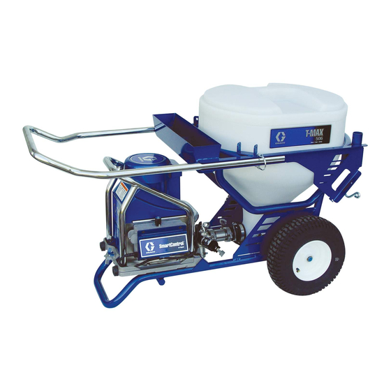
Graco T-Max 506 Operation - Repair - Parts
Texture sprayer
Hide thumbs
Also See for T-Max 506:
- Quick operator's manual (2 pages) ,
- Operation - repair - parts (80 pages) ,
- Quick operator's manual (2 pages)
Table of Contents
Advertisement
Operation, Repair, Parts
™
T-Max
506/657/6912
Texture Sprayer
For portable spraying of water-based materials. Can be used for application of
solvent-based materials only when solvent compatible seals are installed and
solvent compatible, conductive hoses are used. For professional use only.
Not approved for use in European explosive atmosphere locations.
T-Max 506: 50 bar (5 MPa, 725 psi) Maximum Working Pressure
T-Max 657: 65 bar (6.5 MPa, 940 psi) Maximum Working Pressure
T-Max 6912: 69 bar (6.9 MPa, 1000 psi) Maximum Working Pressure
See page 4-6 for model information.
Important Safety Instructions
Read all warnings and instructions in this manual and related manuals before using
the equipment. Be familiar with the controls and the proper usage of the equipment.
Save these instructions.
STX Trigger Gun
T-Max Remote Switch Kit
PrimeValve Accessory Kit
Vibra-Flo T-Max
Air Manifold Kit
Related Manuals
3A6746
Bag Roller Kits
3A6784
T-Max Applicator
3A6785
Free Flow Applicator
3A6909
Inline Applicator
3A6839
www.graco.com/techsupport
3A6748B
312790, 3A4995
312879
313537
309495
EN
Advertisement
Table of Contents

Related Manuals for Graco T-Max 506


Summary of Contents for Graco T-Max 506
- Page 1 For professional use only. Not approved for use in European explosive atmosphere locations. T-Max 506: 50 bar (5 MPa, 725 psi) Maximum Working Pressure T-Max 657: 65 bar (6.5 MPa, 940 psi) Maximum Working Pressure T-Max 6912: 69 bar (6.9 MPa, 1000 psi) Maximum Working Pressure...
-
Page 2: Table Of Contents
T-Max 506/657 ........ - Page 3 Graco Standard Warranty ........
-
Page 4: Models
Models Models T-MAX 506 17 Gallon Power Model Hoses Applicator Hopper Cord 17Z169 Bare Unit 230VAC CEE 7/7 3m whip 17X980 T-Max Applicator 17Z170 Bare Unit 110VAC 3m whip 17X982 T-Max Applicator 17Z291 Bare Unit 230VAC Multi-Cord 3m whip... - Page 5 Models T-MAX 6912 25 Gallon Power Model Hoses Applicator Hopper Manifold Cord 17Z173 Bare Unit 3m whip 17Z626 3m whip T-Max 17X986 Applicator 3m whip Inline 17Z532 Applicator 3m whip Free-Flow 17X990 Applicator 3m whip 17X993 230VAC CEE 7/7...
- Page 6 Models T-MAX 6912 continued 25 Gallon Power Model Hoses Applicator Hopper Manifold Cord 17Z293 Bare Unit 3m whip 17Z628 3m whip T-Max 17X987 Applicator 3m whip Inline 17Z533 Applicator 3m whip Free-Flow 17X991 Applicator 3m whip STX Spray 17X994 ...
-
Page 7: Warnings
Warnings Warnings The following warnings are for the setup, use, grounding, maintenance, and repair of this equipment. The exclamation point symbol alerts you to a general warning and the hazard symbols refer to procedure-specific risks. When these symbols appear in the body of this manual or on warning labels, refer back to these Warnings. - Page 8 All parts of the spray system, including the pump, hose assembly, spray gun, and objects in and around the spray area shall be properly grounded to protect against static discharge and sparks. Use Graco conductive or grounded high-pressure airless material sprayer hoses.
- Page 9 Check hoses and parts for signs of damage. Replace any damaged hoses or parts. • This system is capable of producing 1000 psi (69 bar, 6.9 MPa). Use Graco parts or accessories that are rated a minimum of 1000 psi (69 bar, 6.9 MPa). •...
- Page 10 Warnings WARNING EQUIPMENT MISUSE HAZARD Misuse can cause death or serious injury. • Do not operate the unit when fatigued or under the influence of drugs or alcohol. • Do not exceed the maximum working pressure or temperature rating of the lowest rated system component.
-
Page 11: Component Identification 506
Component Identification 506 Component Identification 506 12 Hopper Plug Pump Module 13 Scraper Tool Hopper Frame 14 Whip Hose Pump 15 Material Hose Pump Outlet 16 T-Max Applicator Pressure Relief Valve 17 Inline Applicator Module Securing Clamp 18 Tool Box Power Cord ON/OFF Switch NOTE: All hoses sent with the unit are for... -
Page 12: Component Identification 657
Component Identification 657 Component Identification 657 12 Hopper Plug Pump Module 13 Scraper Tool Hopper Frame 14 Whip Hose Pump 15 Material Hose Pump Outlet 16 T-Max Applicator Pressure Relief Valve 17 Inline Gun Module Securing Clamp 18 Tool Box Power Cord ON/OFF Switch NOTE: All hoses sent with the unit are for... -
Page 13: Component Identification 6912
Component Identification 6912 Component Identification 6912 14 Hopper Plug Pump Module 15 Signal / Air Hose Hopper Frame 16 Scraper Tool Pump 17 Material Hose Pump Outlet 18 Whip Hose Pressure Relief Valve 19 Tool Box Module Securing Clamp 20 Free Flow Applicator Power Cord 21 STX Spray Gun Pump Mode Switch... -
Page 14: Component Identification
Component Identification Component Identification Free Flow 18m Remote 30m Remote Applicator (17Z128) Switch (17Z157) Switch (17Z158) T-Max Applicator (17Z054) STX Spray Gun 18m Signal/Air 13m Signal/Air (17Y910) Hose (17Z144) Hose (17Z148) 33m Signal/Air Hose (17Z151) Inline Applicator (17Y907) 3A6748B... -
Page 15: Pump Control Settings
Pump Control Settings Pump Control Settings T-Max 506/657 Pump Control Setting Description Pressure Mode The motor will run to meet the pressure determined by the Pressure Control Knob (K). The “Flow Mode with Remote Control” setting allows the user to control ON/OFF... -
Page 16: Preparation
Preparation Preparation Grounding • Flush with a fluid that is compatible with the fluid being dispensed and the equipment wetted parts. • Flush at the lowest pressure possible. Check connectors for leaks and tighten The equipment must be grounded to as necessary. -
Page 17: Extension Cords
Preparation Extension Cords Premix Slowly add water to a 5 gallon (18.9 liter) Use an extension cord with an undamaged bucket of premix. ground contact. If an extension cord is necessary, use a 3-wire, 12 AWG (2.5 mm minimum. NOTE: Lighter gauge or longer extension cords may reduce sprayer performance. -
Page 18: Hose Lubrication Mixing Instructions
Preparation Hose Lubrication Mixing Instructions Hose lubrication (17Z224) is used to lube the Fill remainder of bucket with water. Stir pump and hose passages to reduce the risk for one minute. of packout when priming aggregate material. NOTE: If using other hose lubricants, follow manufacturer’s mixing instructions. -
Page 19: Pressure Relief Procedure
Preparation Pressure Relief Procedure Point applicator into hopper. Turn Follow the Pressure Relief applicator ON. Procedure whenever you see this symbol. This equipment stays pressurized until pressure is manually relieved. To help prevent serious injury from pressurized fluid, such as skin injection, splashing fluid and moving parts, follow the Pressure Relief Procedure when you stop spraying and before cleaning, checking, or... - Page 20 Preparation If you suspect the spray tip or hose is Loosen the retaining nut or the clogged or that pressure has not been coupling completely. fully relieved: Clear the obstruction in the hose or If installed, turn prime valve down to tip.
-
Page 21: Setup
Setup Setup Depending on materials being sprayed with the T-Max 6912, different pump setups might be desired. For disassembly instructions, see Pump Repair, page 60. When unpacking sprayer for the first time or Smooth materials: Use steel inlet after long term storage perform setup ball with spring and steel outlet ball procedure. - Page 22 Setup To remove outlet spring, remove Move module securing clamp down. pump inlet and pump cylinder. Then remove spring from the piston. Connect pump module to hopper frame. Lock front caster. Release hopper clamp. 3A6748B...
- Page 23 Setup If hopper and pump do not align, loosen Turn ON/OFF Switch to OFF. Connect four nuts on back of hopper. Make sure power cord. hopper and pump are aligned and then tighten four nuts. Remove pump plug. Connect material hose to pump outlet.
-
Page 24: Start Up - Airless
Start Up - Airless Start Up - Airless Turn ON/OFF Switch to ON. Perform the start up procedure each time the sprayer is started for the first time after it has been cleaned or stored. Perform Pressure Relief Procedure, page 19. 6912 only: Place Pump Mode Fill material hopper with pre-mixed Switch in up position. - Page 25 Start Up - Airless Once a steady stream flows from Connect applicator to material hose. the material hose, run for an additional 30 seconds. ti11697a Turn ON/OFF Switch to OFF. Turn ON/OFF Switch to ON. Install filter or air passage plug and tip extension.
-
Page 26: Spray Tip Installation
Start Up - Airless Spray Tip Installation Assemble retaining ring on tip guard adapter then assemble tip guard. To avoid serious injury from skin injection do not put your hand in front of the spray tip when installing or removing the spray tip and tip guard. -
Page 27: Clear Spray Tip Clog
Start Up - Airless Clear Spray Tip Clog Rotate spray tip back to spray position. Turn applicator ON. Spray test pattern. To avoid tip clogs: SPRAY • When the applicator is not in use for ti11715a extended periods of time, keep the tip “wet”... -
Page 28: Start Up - Air Assist
Start Up - Air Assist Start Up - Air Assist To prime without outlet spring, remove hose and pour water into the outlet. Place unit in “flow mode” and turn Pressure Control Knob clockwise until material comes out of the pump outlet. - Page 29 Start Up - Air Assist Prime pump. Once a steady stream flows from the material hose, run for an Place material hose in hopper. additional 30 seconds. ti11697a Turn ON/OFF Switch to OFF. Turn ON/OFF Switch to ON. Place Pump Mode Switch in down position.
-
Page 30: Start Up - Air Assist Stx Gun
Start Up - Air Assist STX Gun Start Up - Air Assist STX Gun Turn air needle valve to low setting. Hold applicator over material hopper and Connect applicator to material hose. turn applicator ON. Connect signal wire connector to gun handle, then the air hose. - Page 31 Start Up - Air Assist STX Gun When done spraying, release trigger. Adjust air needle valve and/or select The fluid passage will stay open, alternative nozzle size (4 - 12mm) for relieving pressure. desired finish. When pressure is relieved, press trigger stop button to close fluid passage.
-
Page 32: Operation
Operation Operation The system comes with the following hoses: T-Max 506: • Fluid Hose: 5 m of 25 mm ID & 3 m of 19 mm ID The system has thermal overload protection that will automatically shut T-Max 657: down the sysem if it overheats. To reduce the risk of bodily injury due to the system •... -
Page 33: Cleanup
Cleanup Cleanup Clean hopper sides to material level. Storage less than 24 hours Cover material in hopper with hopper cover. Perform Pressure Relief Procedure, page 19. Remove applicator. Keep applicator “wet” by placing in water or wrapping with a wet cloth. Disconnect pump from hopper. - Page 34 Cleanup Storage more than 24 hours Install hopper plug. Perform Pressure Relief Procedure, page 19. Shut air OFF if spraying with air. Remove applicator from material hose. Clean applicator. ti11711a Install cap on pump inlet. Turn Pressure Control Knob clockwise and pump unused texture from material hopper and hose.
- Page 35 Cleanup Scrape remaining texture in hopper into Insert two wet cleaning balls into pump pump to be pumped from sprayer. outlet. Connect material hose to pump outlet. Fill material hopper with water and clean sides. Rotate pump control to shut pump OFF. Rotate Pressure Control Knob clockwise to start pump.
- Page 36 Cleanup 10. Run pump until cleaning balls exit 13. Turn Pressure Control Knob clockwise material hose. Hold material hose to start pump. securely while passing balls through it. Pressure can build up and make hose jump. Save cleaning balls. 11. Rotate Pressure Control Knob to shut pump OFF.
- Page 37 Cleanup 16. Rotate Pressure Control Knob to shut 19. Clean applicators, spray tips and guard pump off. with brush. 17. Disconnect pump from hopper. 18. Flush hopper with water. Clean and install drain plug. 3A6748B...
- Page 38 Cleanup 20. Clean hardened material from applicator nozzles with air nozzle cleaner. NOTICE Do not use air nozzle cleaner to clean applicator check valve and spray tip. Doing so will damage both items. ti11811a ti11847a 3A6748B...
-
Page 39: Troubleshooting
Troubleshooting Troubleshooting Follow Pressure Relief Procedure, page 19, before checking or repairing. Check all possible problems and causes before disassembling unit. Motor Will Not Operate Problem Cause Solution Basic Fluid Pressure Problems Pressure control knob setting. Slowly increase pressure setting to Motor will not run if at minimum see if motor starts. - Page 40 Troubleshooting Problem Cause Solution Basic Electrical Problems Motor control board. Board shuts See Control Board Diagnostics, down and displays error code. page 43. Electrical supply. Meter must read: Reset building circuit breaker; 210-255 Vac for 220-240 Vac replace building fuse. Try another models;...
- Page 41 Troubleshooting Low or Fluctuating Output Problem Cause Solution Low Output Worn spray tip. Follow Pressure Relief Procedure Warning, then replace tip. See your separate gun or tip manual. Verify pump does not continue to Service pump. Check piston and stroke when applicator is turned off. intake valves for wear or obstructions.
- Page 42 Troubleshooting Problem Cause Solution Motor runs but pump does not Pump pin damaged or missing. Replace pump pin if missing. Be stroke sure retainer spring is fully in groove all around connecting rod. Connecting rod assembly is Replace connecting rod assembly. damage.
-
Page 43: Repair
Repair Repair Control Board Diagnostics Perform Pressure Relief Procedure, Observe display messages in the page 19. following table. NOTE: Do not allow sprayer to develop fluid Observe LED operation and reference pressure without transducer installed. Leave the following table. pump outlet open if test transducer is used. Control board status Display... - Page 44 Repair Control board status Display LED Blinks Spray Operation Indicates What to Do CODE 08 Eight times Sprayer does not operate. Voltage supply to Set sprayer to OFF and repeatedly low. disconnect power to sprayer remove other equipment that uses the same circuit. Locate a good voltage supply to avoid damage to electronics.
-
Page 45: Control Board Removal 506/657
Repair Control Board Removal Remove four screws and motor cover. 506/657 Perform Pressure Relief Procedure, page 19. Unplug power cord to disconnect power. Separate pump from hopper. Remove four screws and control cover. Disconnect display from control board. ti11854a 3A6748B... - Page 46 Repair Reference Wiring Diagram, page 81. Remove ON/OFF switch toggle boot. Remove screw. Disconnect ground, blue and brown leads. ti11853a Remove power cord from control box. Disconnect black lead from control board to filter board. Remove filter board screws. 10. Remove filter board from control box. ti11856a 3A6748B...
-
Page 47: Control Board Installation 506, 657
Repair Control Board Installation 11. Remove screw from bottom of control box. 506, 657 Install control board with four screws. ti11864a 12. Disconnect motor (A), thermister (B), potentiometer (C) and transducer (D) ti11863a connectors. Remove grommet (E). Connect motor (A), thermister (B), potentiometer (C) and transducer (D) connectors. - Page 48 Repair Install filter board in control box. Install filter board screw. ti11856a Install power cord (C) in control box. Connect black lead from control board to filter board. Reference Wiring Diagram, page 81. Connect ground, blue and brown leads. Install screw. Install ON/OFF switch toggle boot.
-
Page 49: Control Board Removal 6912
Repair Control Board Removal 10. Connect display to control board. Install control cover with four screws. 6912 Perform Pressure Relief Procedure, page 19. Unplug power cord to disconnect power. ti11854a Separate pump from hopper. 11. Install motor cover with four screws. ti11737a 3A6748B... - Page 50 Repair Remove four screws and motor cover. Remove four screws and open cover. Remove two screws and remove filter board and amp switch. 3A6748B...
-
Page 51: Control Board Installation 6912
Repair Reference Wiring Diagrams, page 82. Disconnect motor leads, thermal switch, Disconnect mode switch (yellow and and motor hall/encoder sensor. Remove black), transducer, potentiometer, amp grommet. switch, LED display filter board (black, blue). Remove front cover. Remove two screws from back of control box and remove box. - Page 52 Repair Connect motor leads, thermal switch, Install filter board in control box with two and motor hall/encoder sensor. Install screws. Install amp switch. grommet. Reference Wiring Diagrams, page 82. Connect mode switch (yellow and black), transducer, potentiometer, amp Close cover and install four screws. switch, LED display filter board (black, blue).
- Page 53 Repair Install motor cover using four screws. Connect pump to hopper. 3A6748B...
-
Page 54: Pump Removal
Repair Pump Removal Remove four screws and motor cover. Perform Pressure Relief Procedure, page 19. Unplug power cord to disconnect power. Perform Storage more than 24 hours procedure, page 34. Separate pump from hopper. Remove four screws and control cover. 506/657 ti11854a 6912... - Page 55 Repair Disconnect transducer from control Loosen retaining nut. board. Remove transducer and strain relief from control box. Slowly rotate fan blade on motor until connecting rod is at bottom of stroke. 10. Unscrew pump from bearing housing. ti11867a Pry retaining spring up on connecting rod toward motor.
-
Page 56: Pump Installation
Repair Pump Installation Tighten retaining nut. Push piston rod out of pump 50 to 70 mm (2 to 2.8 in.). ti11879a Screw retaining nut onto pump until it stops. Screw pump into bearing housing until pump stops. Unscrew pump until pump outlet is 13°... - Page 57 Repair Install transducer and strain relief in Install motor cover with four screws. control box. Connect transducer to control board. Install control cover with four screws. 506/657 Connect pump module. 6912 ti11854b 3A6748B...
-
Page 58: Pump Repair 506/657
Repair Pump Repair 506/657 Remove packing nut. Push piston rod from outlet housing. Disassembly NOTE: It may be easier to leave the pump connected to the connecting rod and bearing housing if the only assembies to be cleaned and inspected are the intake housing or piston valve. - Page 59 Repair Assembly Install packing nut. Hand tighten then tap with screw driver. Push piston rod into Place end of piston rod in vise. Install outlet housing. Extend piston rod 50 - 75 new piston seal. Torque piston valve to mm (A) out of outlet housing. 27 ft-lb (36,6 N·m).
-
Page 60: Pump Repair 6912
Repair Pump Repair 6912 Install clamp on pump cylinder. Torque clamp to 100in-lb (11.3 Nm). Disassembly NOTE: It may be easier to leave the pump connected to the connecting rod and bearing housing if the only assembies to be cleaned and inspected are the intake housing or piston valve. - Page 61 Repair Remove clamp and pump cylinder. Place cage of piston rod in vise and remove piston valve. Remove piston Remove packing nut. Push piston rod seal. Remove packings and glands from from outlet housing. Remove throat piston rod. Inspect all parts for nicks and packings and glands from cylinder.
- Page 62 Repair Assembly Install packing nut. Hand tighten then tap with screw driver. Push piston rod into Place cage of piston rod in vise. Install outlet housing. Extend piston rod 50 - 75 new piston seal. Torque piston valve to mm (A) out of outlet housing. 90 ft-lb (122 N·m).
-
Page 63: Cross-Section Reference / Pump Ball Identification 6912
Repair Cross-Section Reference / Pump Ball Identification 6912 3A6748B... -
Page 64: Motor Removal
Repair Motor Removal Remove four screws, washers and bearing housing. Perform Pressure Relief Procedure, page 19. Unplug power cord to disconnect power. Remove pump. See Pump Removal, page 54. Tip unit on back. NOTE: Do not drop gear cluster when removing drive housing. -
Page 65: Motor Installation
Repair Motor Installation Install motor with two screws. Torque to 200 - 220 in-lbs (22.6 - 24.9 N·m). NOTICE When installing motor, carefully align gears to avoid damaging mating parts. Install drive housing with three screws. Install fan with screw. Torque 11 - 13 in-lb (1.24 - 1.46 N·m). -
Page 66: Recycling And Disposal At End Of Life
Repair Recycling and Disposal at End of Life At the end of the product’s useful life, Dismantle and recycle: dismantle and recycle it in a responsible • Remove motors, circuit boards, LCDs manner. (liquid crystal displays), and other electronic components. Recycle Preparation: according to applicable regulations. - Page 67 Notes Notes 3A6748B...
-
Page 68: Parts - Hopper Frame
Parts - Hopper Frame Parts - Hopper Frame 3A6748B... -
Page 69: Parts List - Frame
Parts - Hopper Frame Parts List - Frame Description Ref. Part Description Ref. Part 19A674 BRACKET, guide, hopper 19A673 FRAME, hopper, Tmax 113796 SCREW, flanged, hex hd 156306 WASHER, flat HOPPER, material 116038 WASHER, wave spring 20a 25E541 17 gallon 119509 WHEEL, pneumatic 20b 25E542 25 gallon 120211 RING, retaining, e-ring... -
Page 70: Parts - Power Module 506/657
Parts - Power Module 506/657 Parts - Power Module 506/657 PAGE PAGES 74, 75 3A6748B... -
Page 71: Parts List - Power Module 506/657
Parts - Power Module 506/657 Parts List - Power Module 506/657 Description Ref. Part Description Ref. Part 19A713 BUMPER, rubber 287234 HOUSING, drive, Tmax 115483 NUT, lock 103374 SCREw, mach, rhd 287235 HOUSING, drive, Tmax 106062 WHEEL, semi- pneumatic 116192 WASHER, thrust 101242 RING, retaining 114672 WASHER, thrust 104811 CAP, hub... -
Page 72: Parts - Power Module 6912
Parts - Power Module 6912 Parts - Power Module 6912 PAGE PAGE 76 3A6748B... -
Page 73: Parts List - Power Module 6912
Parts - Power Module 6912 Parts List - Power Module 6912 Description Ref. Part Description Ref. Part 115483 NUT, lock 24M008 HOUSING, drive 103374 SCREW, mach 116192 WASHER, thrust 106062 WHEEL, semi- 114672 WASHER, thrust pneumatic 114699 WASHER, thrust 101242 RING, retaining 243951 GEAR, combination 104811 CAP, hub 25P037 KIT, repair, motor... -
Page 74: Parts - Pump 289555 (506)
Parts - Pump 289555 (506) Parts - Pump 289555 (506) Parts List - Pump Ref. Part Description Ref. Part Description 501095 SPRING, ball check 15D117 TUBE, fiber, pump 121588 O-RING 107185 PACKING, o-ring 101822 BALL, bearing 118597 PACKING, u-cup 15D116 SEAL, piston 15R739 HOUSING, outlet,... -
Page 75: Parts - Pump 289556 (657)
Parts - Pump 289556 (657) Parts - Pump 289556 (657) Parts List - Pump Ref. Part Description Ref. Part Description 501095 SPRING, ball check 15D117 TUBE, fiber, pump 121587 O-RING 107185 PACKING, o-ring 101822 BALL, bearing 118597 PACKING, u-cup 15D116 SEAL, piston 15R621 HOUSING, outlet,... -
Page 76: Parts - Pump 25E668 (6912)
Parts - Pump 25E668 (6912) Parts - Pump 25E668 (6912) 3A6748B... -
Page 77: Parts List - Pump 25E668 (6912)
Parts - Pump 25E668 (6912) Parts List - Pump 25E668 (6912) Ref. Part Description Ref. Part Description 10† 130792 O-RING 19A610 HOUSING, outlet, 620223 CLAMP machining 17Z241 HOUSING, intake ball 2† 187939 GLAND, male 235962 SEAL, foot valve 3† 187071 PACKING, vee 19A692 GUIDE, ball, inlet 4†... -
Page 78: Parts - Control Box 506/657
Parts - Control Box 506/657 Parts - Control Box 506/657 3A6748B... -
Page 79: Parts List - Control Box 506/657
Parts - Control Box 506/657 Parts List - Control Box 506/657 Ref. Part Description Ref. Part Description 15B120 GROMMET, transducer 277228 BOX, control 121453 CLAMP, wire 15G562 BUSHING, control box 15T342 CONDUIT, corrugated 256219 POTENTIOMETER 15B469 CORD, st, UK 116167 KNOB, potentiometer 158470 CORD, st, CE... -
Page 80: Parts - Control Box 6912
Parts - Control Box 6912 Parts - Control Box 6912 Parts List - Control Box Ref. Part Description Ref. Part Description 277228 BOX, control 17D888 POTENTIOMETER 15G562 BUSHING, control box 15C973 GASKET 287913 FILTER, board 116167 KNOB, potentiometer 120405 SCREW, mach, hex 130863 SWITCH, toggle washer hd... -
Page 81: Wiring Diagrams
Wiring Diagrams Wiring Diagrams 506/657 3A6748B... -
Page 82: 6912 - Us
Wiring Diagrams 6912 - US 3A6748B... -
Page 83: 6912 - Uk
Wiring Diagrams 6912 - UK 3A6748B... -
Page 84: Technical Specifications
Technical Specifications Technical Specifications T-Max 506 Metric Power requirements ..100-120 Vac 220-240 Vac 50/60 Hz, 13A 50/60 Hz, 8A Motor..... . 1.2 HP... - Page 85 Technical Specifications T-Max 657 Metric Power requirements ..100-120 Vac 220-240 Vac 50/60 Hz, 13A 50/60 Hz, 8A Motor ..... . 1.2 HP 900 W Maximum fluid working pressure.
-
Page 86: California Proposition 65
Technical Specifications T-Max 6912 Metric Power requirements ..100-120 Vac 220-240 Vac 50/60 Hz, 15/20A 50/60 Hz, 10/16A Motor..... . 2.5 HP 1864 W Maximum fluid working pressure 1000 psi 6.9 MPa, 69 bar... -
Page 87: Graco Standard Warranty
Graco’s written recommendations. This warranty does not cover, and Graco shall not be liable for general wear and tear, or any malfunction, damage or wear caused by faulty installation, misapplication, abrasion, corrosion, inadequate or improper maintenance, negligence, accident, tampering, or substitution of non-Graco component parts. -
Page 88: Graco Information
For the latest information about Graco products, visit www.graco.com. For patent information, see www.graco.com/patents. TO PLACE AN ORDER, contact your Graco distributor or call 1-800-690-2894 to identify the nearest distributor. All written and visual data contained in this document reflects the latest product information available at the time of publication.