Table of Contents
Advertisement
Quick Links
Instruction Manual
Form 1446
November 2006
2502 Series Level-Trol
Contents
. . . . . . . . . . . . . . . . . . . . . . . . . . . . . . .
. . . . . . . . . . . . . . . . . . . . . . . . .
. . . . . . . . . . . . . . . . . . . . . . . . . . . . . .
. . . . . . . . . . . . . . . . . . . . . . . . . . . .
. . . . . . . . . . . . . . . . . . . . . . . . . . . . . . . .
. . . . . . . . . . . . . . . . . . . . . . . . . . . . . . . .
. . . . . . . . . . . . . . . . . . . . . . . . .
. . . . . . . . . . . . . . . . . . . . . . . . . . . .
. . . . . . . . . . . . . . . . . . . . . . . . . . . . . . .
. . . . . . . . . . . . . . . . . . . . . . . . .
. . . . . . . . . . . . . . . . . . . . . . . . .
. . . . . . . . . . . . . . . . . . . . . . . .
. . . . . . . . . . . . . . . . . . . . . . .
. . . . . . . . . . . . . . . . . . . . . . . . . . . . . . . . . .
Type 2502F Controller with Reset
. . . . . . . . . . . . . . . . . . . . . . . . . .
. . . . . . . . . . . . . . . . . . . . . . . . . . . . .
. . . . . . . . . . . . . . . . . . . . . . . . .
. . . . . . . . . . . . . . . . . . . . . . . . .
www.Fisher.com
. . . . . . . . . . . . . . . . . . . . . .
. . . . . . . . . . . . . . . . . . . . . . .
. . . . . . . . . . . . . . . . . . . . .
. . . . . . . . . . . . . . . . . . .
. . . . . . . . . . . . . . . . . .
. . . . . . . . . . . . . . .
. . . . . . . . . . . . . . . . . . . .
. . . . . . . . . . . . . . . . . . . .
. . . . . . . . . . . . . . . .
. . . . . . . . . . . . . . . . . . .
. . . . . . . . . . . .
. . . . . . . . . . . . . . . . . . . . . .
. . . . . . . . . . . .
. . . . . . . . . . . . . .
. . . . . . . . . . . . . . . . . . . .
. . . . . . . . . . . . . . . . . . . . .
. . . . . . . . . . . . . . . . . . . . .
. . . . . . . . . .
. . . . . . . . . . . . . . .
. . . . . . . . . . . . .
. . . . . . . . . . . . . . . . .
. . . . . . . . . . . . . . . . .
2502 Series Controllers
R
Controller
1
1
2
2
2
2
4
5
5
5
6
7
8
8
9
9
11
11
11
11
12
12
W8334
12
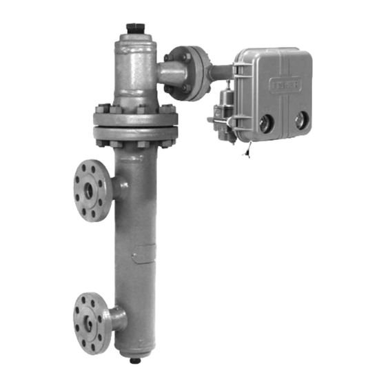
Figure 1. Type 2502 Controller Mounted on
12
12
12
13
14
15
15
Introduction
15
17
Scope of Manual
18
This instruction manual provides installation,
18
operating, calibration, and maintenance procedures
18
for 2502 Series pneumatic controllers (figure 1) used
20
in combination with 249 Series level sensors.
20
This manual does not include regulator or sensor
21
installation or maintenance procedures. For this
21
information, refer to the instruction manual for the
21
appropriate regulator and 249 Series level sensor.
TYPE 2502
CONTROLLER
249B SERIES SENSOR
Type 249B Sensor
. . . . . . . . . . . . . . . . . . . . . . .
. . . . . . . . . . . . . . . . . . . . . . . .
. . . . . . . . . . . . . . . . . . . . . . . . . . . .
. . . . . . . . . . . . . . . . . . . . . . . . . . . . . . . .
. . . . . . . . . . . . . . . . . . . . . . . . . . . . . . . .
22
22
23
23
23
Advertisement
Table of Contents

Related Manuals for Emerson Fisher Level-Trol 2502 Series


Summary of Contents for Emerson Fisher Level-Trol 2502 Series
-
Page 1: Table Of Contents
Instruction Manual Form 1446 2502 Series Controllers November 2006 2502 Series Level-Trol Controller Contents Introduction ....... Scope of Manual . -
Page 2: Description
If you have any questions about these product. Responsibility for the instructions, contact your Emerson Process selection, use, and maintenance of any Managementt sales office before proceeding. product remains with the purchaser and end-user. - Page 3 Instruction Manual Form 1446 2502 Series Controllers November 2006 Table 1. Specifications Available Configurations Maximum Supply Pressure 3.4 bar (50 psig) Type 2502: A direct-acting controller which provides proportional-plus-reset control Type 2502C: A Type 2502 with a level indicator Supply Pressure Consumption assembly At 1.4 bar (20 Psig) Type 2502F: A Type 2502 with a differential relief...
-
Page 4: 249 Series Sensors
Instruction Manual Form 1446 2502 Series Controllers November 2006 Table 1. Specifications (continued) Hazardous Area Classification Declaration of SEP 2502 Series controllers comply with the Fisher Controls International LLC declares this requirements of ATEX Group II Category 2 Gas product to be in compliance with Article 3 and Dust paragraph 3 of the Pressure Equipment Directive (PED) 97 / 23 / EC. -
Page 5: Uncrating
Instruction Manual Form 1446 2502 Series Controllers November 2006 process pressure or liquid. This danger may not be readily apparent ADJUSTING PRESSURE SCREW when disassembling the sensor or LOCKNUT REGULATOR removing the displacer. Before 1/4”-18 NPT SUPPLY disassembling the sensor or removing CONNECTION the displacer, observe the more specific warning provided in the... -
Page 6: Mounting Caged Sensors
Instruction Manual Form 1446 2502 Series Controllers November 2006 STYLE 1: TOP STYLE 2: TOP AND BOTTOM AND LOWER SIDE RIGHT-HAND MOUNTING SCREWED: S2 SCREWED: S1 FLANGED: F2 FLANGED: F1 STYLE 2: UPPER STYLE 2: UPPER AND LOWER SIDE SIDE AND BOTTOM AH9150−A LEFT-HAND MOUNTING A2613−2/IL... -
Page 7: Mounting Cageless Sensors
Instruction Manual Form 1446 2502 Series Controllers November 2006 VENT CENTER OF LIQUID OR EQUALIZING INTERFACE LINE SHUTOFF LEVEL VALVES DRAIN W0645-1 SIDE (SHOWING STILLWELL) DF5379-A A6771/IL Figure 6. Caged Sensor Mounting Mounting Cageless Sensor Note MOUNTED If a stillwell is used, it must be installed plumb so that the displacer does not touch the wall of the stillwell. -
Page 8: Side-Mounted Sensor
Instruction Manual Form 1446 2502 Series Controllers November 2006 Note If the controller is not mounted on the DISPLACER STEM sensor, refer to the Installing END PIECE Controller on Sensor section. This section also provides instructions for adding a heat insulator to a unit. DISPLACER ROD DISPLACER STEM... -
Page 9: Regulator Supply Pressure
During startup, it is necessary to change process diameter will suffice in most levels to position the displacer from its maximum to applications, check with an Emerson its minimum range of operations. Provide a means to Process Management field office and change the process level or interface. - Page 10 Instruction Manual Form 1446 2502 Series Controllers November 2006 POINTER ASSEMBLY 30A8943-H 29A2834-C TYPE 2502C LEVEL INDICATOR A1933/IL INSTRUCTION LABEL WITH RIGHT-HAND MOUNTING RAISE LEVEL DIAL FOR RESET ADJUSTMENT LEFT-HAND MOUNTING MOUNTING SCREWS W5637/IL/A 21A6447-A ADJUSTING A1903/IL SCREW 1E8731-C 1E8732-C A1897-1/IL TYPICAL RIGHT-HAND MOUNTED DIFFERENTIAL RELIEF VALVE...
-
Page 11: Adjustments
Instruction Manual Form 1446 2502 Series Controllers November 2006 Adjustments than 0.2 bar (3 psig) for the 0.2 to 1.0 bar (3 to 15 psig) range or 0.4 bar (6 psig) for the 0.4 to 2.0 bar Controller adjustments are provided in this section. (6 to 30 psig) range. -
Page 12: Differential Relief Adjustment
Instruction Manual Form 1446 2502 Series Controllers November 2006 Differential Relief Adjustment displacer to an appropriate depth in a liquid having a specific gravity equal to that of the process liquid. The differential relief valve protrudes from the back of the controller case on a construction with an F in If necessary, use water for wet calibration in the the type number. -
Page 13: Determining Suspended Weight For Calibration
= Volume of the displacer submerged by the applications under dry conditions, lighter liquid, in cubic inches. consult your Emerson Process Management sales office for the maximum allowable substitute weight that can be used with your V = π/4 (displacer diameter) -
Page 14: Calibration Procedure
Instruction Manual Form 1446 2502 Series Controllers November 2006 Table 2. Minimum and Maximum Limits for Setting Process Variables Application Minimum Limit Maximum Limit Liquid level Displacer must be completely out of liquid Displacer must be completely submerged in liquid Displacer must be completely submerged in the upper Displacer must be completely submerged in the lower Interface... -
Page 15: Startup
Instruction Manual Form 1446 2502 Series Controllers November 2006 Startup applied to the controller, which uses a nozzle, bellows, and pneumatic relay to convert the rotary Adjustment locations are shown in figure 9. motion to a standard pneumatic output signal. The output signal is sent to a final control element. - Page 16 Instruction Manual Form 1446 2502 Series Controllers November 2006 TORQUE PROPORTIONAL TUBE SHAFT BELLOWS FIXED MOVABLE PIVOTING PIVOT CROSS LEVEL SET SPRINGS ADJUSTMENT FIXED BEAM AND NOZZLE PIVOT FLAPPER RESET RESET BELLOWS VALVE PROPORTIONAL VALVE FIXED RESTRICTION EXHAUST END OF RELAY LARGE VALVE DIAPHRAGM...
-
Page 17: Relief Valve
Instruction Manual Form 1446 2502 Series Controllers November 2006 LEVEL SET MOVABLE ARM PROPORTIONAL ADJUSTMENT BELLOWS RELIEF INNER CHAMBER VALVE DIFFERENTIAL FIXED RELIEF VALVE PIVOT PIVOTING BEAM AND CROSS FLAPPER DIAPHRAGM SPRINGS NOZZLE ASSEMBLY RESTRICTION RESET RELIEF BELLOWS RESET DIAPHRAGM VALVE OUTER CHAMBER... -
Page 18: Maintenance
Instruction Manual Form 1446 2502 Series Controllers November 2006 chamber pressure exceeds that in the inner relief that must be taken to protect against valve chamber by the amount of the relief pressure process media. setting, the relief diaphragm will move off the orifice in the relief valve, and the pressure in the outer chamber will bleed into the reset system. - Page 19 Instruction Manual Form 1446 2502 Series Controllers November 2006 Table 3. Troubleshooting Chart for 2502 Series Controllers Fault Possible Cause Check Correction 1. Process wanders or cycles 1.1 Proportional band or specific 1.1 Insure the prestartup 1.1 If stable control cannot be around setpoint.
-
Page 20: Changing Mounting Method
Instruction Manual Form 1446 2502 Series Controllers November 2006 3. Remove any insulating tape from the joint between the controller case and the torque tube arm. Remove the four cap screws (key 39, figure 12) that hold the controller or heat insulator to the torque tube arm. -
Page 21: Changing Proportional, Reset, Or
Instruction Manual Form 1446 2502 Series Controllers November 2006 as shown in the figure. Then mount the insulator 2. To change the reset restriction valve assembly assembly (key 35) on the controller case with four (key 91), remove the two mounting screws (key 182) washers (key 53) and button-head cap screws located on the back side of case. -
Page 22: Replacing Bellows
Instruction Manual Form 1446 2502 Series Controllers November 2006 4. Install a new gasket, the replacement relay if SEAL SCREW necessary, and both mounting screws. Reconnect RINGS the tubing. On a controller with indicator assembly, slide the base plate under the two lower screws of SEAL SCREW the relay case, align the plate so that the pointer will... -
Page 23: Parts Ordering
Heat Insulator Parts Kit Contains keys 35, 36, 37, 38, 39, 40, and 53 R2500XH0012 Whenever corresponding with your Emerson Process Management sales office about this equipment, always mention the controller type number and the serial number found on the unit Parts List nameplate (figure 9). - Page 24 Instruction Manual Form 1446 2502 Series Controllers November 2006 30A8942-H/DOC 43A2366-H/DOC 30A8943-H/DOC Figure 14. 2502 Series Controller Constructions...
- Page 25 Instruction Manual Form 1446 2502 Series Controllers November 2006 Description Part Number Description Part Number Pressure Gauge (2 req’d) Nozzle, stainless steel 1U639135132 Triple Scale Beam, steel, pl 1K873825072 Brass Flapper, K93600 alloy 1J416241132 0-30 psig/0-0.2MPa/0-2.0 bar 11B8577X012 Flapper Base, stainless steel 1J416335032 0-60 psig/0-0.4MPa/0-4.0 bar 11B8577X022...
- Page 26 Instruction Manual Form 1446 2502 Series Controllers November 2006 Description Part Number Description Part Number Differential Relief Valve Ass’y, Types 2502F Machine Screw, stainless steel, (2 req’d) and 2502FC Types 2502 and 2502C (not shown) 1B7839X0012 Standard 21A6447X0A2 Type 2502F and 2502FC 1C8969X0012 High temperature 21A6447X012...
- Page 27 Instruction Manual Form 1446 2502 Series Controllers November 2006...
- Page 28 November 2006 Level-Trol and Fisher are marks owned by Fisher Controls International LLC, a member of the Emerson Process Management business division of Emerson Electric Co. Emerson Process Management, Emerson, and the Emerson logo are trademarks and service marks of Emerson Electric Co.