Advertisement
NOTE: Read the entire instruction manual before starting the
installation.
This symbol → indicates a change since the last issue.
TABLE OF CONTENTS
Safety Considerations.....................................................................1
Installation Considerations.............................................................1
Introduction ....................................................................................1
Installation...................................................................................1-4
Sequence Of Operation...............................................................4-7
Thermostat Wiring ......................................................................6-8
Care And Maintenance ..................................................................8
Troubleshooting ........................................................................9-11
Wiring Diagrams.....................................................................12-16
Wiring Diagram Notes.................................................................16
SAFETY CONSIDERATIONS
Improper installation, adjustment, alteration, service, maintenance,
or use can cause fire, electrical shock, or other conditions which
may cause personal injury or property damage. Consult a qualified
installer, service agency, or your distributor or branch for infor-
mation or assistance. The qualified installer or agency must use
factory-authorized kits or accessories when modifying this prod-
uct. Refer to the individual instructions packaged with the kits or
accessories when installing.
Follow all safety codes and wear safety glasses. Have fire
extinguisher available. Read these instructions thoroughly and
follow all warnings or cautions attached to the unit. Consult local
and state building codes and Sheet Metal and Air Conditioning
National Association (SMACNA) for special installation require-
ments.
Recognize safety information. This is the safety-alert symbol
When you see this symbol on the unit or in instructions and
manuals, be alert to the potential for personal injury.
Understand the signal words DANGER, WARNING, or CAU-
TION. These words are used with the safety-alert symbol. DAN-
GER identifies the most serious hazards which will result in severe
personal injury or death. WARNING signifies hazards which
could result in personal injury or death. CAUTION is used to
identify unsafe practices which would result in minor personal
injury or product and property damage.
INSTALLATION CONSIDERATIONS
→
1. Install in non-condensing area with ambients between 32°F
and 150°F.
2. Use vibration isolators (flex connectors) on zone dampers
and ductwork to minimize noise.
3. Place dampers away from areas that may be noise sensitive.
4. TXV is required in air conditioning and heat pump appli-
cations.
5. Use separate isolated transformer to supply power to Zone
Perfect Two-Zone Center. (40va minimum, class 2, trans-
former, field supplied)
installation instructions
ZONE PERFECT™
TWO-ZONE
PAGE
.
—1—
Cancels: II ZONEKIT-0-2
Y2
T'sta t
Equp imt
Y1
HP
R
Fnc
W1
DTO
W2
Fnc Ht
C
Off
w/oF
On
w/F
G Y2 Y1
R W1 W2 C
Sens ors
HP
Du ct
→
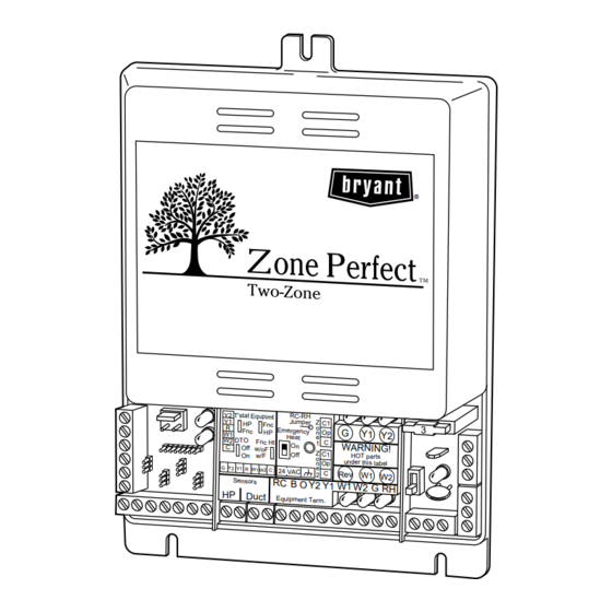
Fig. 1—Zone Perfect Two-Zone System
(Shown Without Cover)
6. Load calculations must be performed to determine equip-
ment size. Equipment selection is matched to block load. It
is imperative equipment is not over sized.
7. Ductwork must be designed based off the sum of peak plus
25 percent oversize. It is imperative ductwork is not under
sized.
INTRODUCTION
The Zone Perfect Two-Zone System allows the air conditioning
and heating equipment to control temperatures in 2 distinct spaces
or zones within a building. Each zone has independent temperature
settings controlled by a thermostat.
NOTE: Thermostats are purchased separately.
The comfort temperature settings can change automatically
through the use of schedules if programmable thermostats are
selected. This allows Zone Perfect Two-Zone to change the
temperature settings in zones to reflect occupancy or usage. The
Zone Perfect Two-Zone System uses motorized air volume control
dampers (also called zone dampers) to regulate the flow of
conditioned air into the zones.
INSTALLATION
I. CHECK EQUIPMENT AND JOBSITE
A. Inspect Equipment
File claim with shipping company, prior to installation, if shipment
is damaged or incomplete.
ZONEKIT
II ZONEKIT-0-6
®
RC-R H
Jum per
Z
C1
Fnc
o
3
Eme rgen cy
G
HP
n
Op
Y1
Y2
Heat
e
C
1
On
WA RN ING !
Z
Off
C1
HOT parts
o
unde r this labe l
n
Op
e
24 VAC
C
Rev
2
W1 W2
RC B O Y2 Y1
W1 W2 G RH
Equi pme nt Term .
6-97
A97291
Advertisement
Table of Contents

Related Manuals for Bryant ZONE PERFECT TWO-ZONE


Summary of Contents for Bryant ZONE PERFECT TWO-ZONE
- Page 1 INTRODUCTION Understand the signal words DANGER, WARNING, or CAU- The Zone Perfect Two-Zone System allows the air conditioning TION. These words are used with the safety-alert symbol. DAN- and heating equipment to control temperatures in 2 distinct spaces GER identifies the most serious hazards which will result in severe or zones within a building.
-
Page 2: Install Zone Dampers
RELEASE and de-energized during operation and may be an annoyance. BUTTON MOUNTING Install Zone Perfect Two-Zone in an area with a temperature range (RED) BRACKET between 32°F and 150°F. FIELD Install Zone Perfect Two-Zone center in a vertical position. - Page 3 NOTE: The barometric bypass damper is a critical part of the with actuator. Zone Perfect Two-Zone System for control of minimum airflow 4. Insulate damper using 1-1/2-in. to 2-in. insulation. (Check and noise reduction. It is recommended that the bypass be your local codes.) (See Fig.
- Page 4 (See Fig. 12 for connection to Zone Perfect HVAC EQUIPMENT CONNECTIONS Two-Zone center.) The Zone Perfect Two-Zone relay outputs are shown in Table 1. SEQUENCE OF OPERATION The Y1 and Y2 contacts are used for the compressor contactor only. Zone Perfect Two-Zone operates the heat pump by energiz- I.
- Page 5 3 positions, then 1 position every 20 connected to zone module input. sec there after until full open. Zone Perfect Two-Zone will not shut 2. If selected thermostat is a heat pump (HP) or 2-speed (2S) down second-stage cooling (if used);...
- Page 6 ONLY HOOKUP "C" WHEN SUPPLIED BY THERMOSTAT † HOOKUP WHEN USING APPLICABLE TWO-STAGE † HOOKUP WHEN USING APPLICABLE TWO-STAGE THERMOSTATS WITH TWO-STAGE EQUIPMENT THERMOSTATS WITH TWO-STAGE EQUIPMENT A93494 A93495 → Fig. 12—Zone Perfect Two-Zone Circuit Board with Standard Thermostat Wiring —6—...
- Page 7 A97294 → Fig. 13—Electronic Non-Programmable Thermostat Wiring Diagrams TIMEGUARD The Zone Perfect Two-Zone provides equipment protection with an internal 5-minute timeguard delay. This delay is present upon initial power up. There is also a 5-minute timeguard delay for all cooling (Y1) and heat pump modes. The time guard can be cleared by using the comprotec override feature.
-
Page 8: Care And Maintenance
CARE AND MAINTENANCE For continuing optimum performance and to minimize possible The Zone Perfect Two-Zone will allow a maximum of 4 equip- equipment failure, it is essential that periodic maintenance be ment cycles per hr or 1 every 15 minutes when a heating or cooling performed on this equipment. -
Page 9: Troubleshooting
When DTO is On, temperature is sensed by duct This section contains information to assist you in troubleshooting temperature sensor. When the duct temperature problems and errors associated with the Zone Perfect Two-Zone reaches this temperature setting, the duct temperature system. See Table 2. - Page 10 Red LED—Displays ON when first-stage heat is Red LED—Displays ON when fan is energized. energized. Red LED—Displays ON when first-stage cooling is Red LED—Displays ON when second-stage heat energized. is energized. Red LED—Displays ON when second-stage cooling is J2 (Not Shown)—Cut for 50 hz operation. Lo- energized.
-
Page 11: Wiring Diagrams
→ Table 3 shows a temperature/ohm/voltage relationship to help aid in troubleshooting the Zone Perfect Two-Zone System. This table will evaluate both the Duct/HP temperature sensor operation. Use a digital multimeter to perform the following: To verify a sensor is good, disconnect both leads from the I/O board and measure the resistance through the sensor. Match ohm reading to table and compare temperature reading on table to ambient temperature surrounding sensor (Accuracy should be ±... - Page 12 TWO-ZONE SYSTEM 2-STAGE OR VARIABLE-SPEED TWO-ZONE SYSTEM FURNACE SINGLE-STAGE FURNACE SINGLE-SPEED SINGLE-SPEED AIR CONDITIONER AIR CONDITIONER W/W1 Y/Y2 A97296 → Fig. 15—Single-Stage Furnace A97297 With Single-Speed Air Conditioner → Fig. 16—Two-Stage or Variable-Speed Furnace With Single-Speed Air Conditioner TWO-ZONE SYSTEM SINGLE-SPEED TWO-ZONE SYSTEM AIR CONDITIONER...
- Page 13 2-SPEED 2-SPEED AIR CONDITIONER AIR CONDITIONER SINGLE-STAGE 2-STAGE OR TWO-ZONE SYSTEM FURNACE VARIABLE-SPEED TWO-ZONE SYSTEM FURNACE W/W1 Y/Y2 See note 2 See notes 2 and 3 A97300 A97301 → Fig. 19—Single-Stage Furnace → Fig. 20—Two-Stage or Variable-Speed Furnace With 2-Speed Air Conditioner With 2-Speed Air Conditioner 2-SPEED 2-SPEED...
- Page 14 SINGLE-SPEED INTERFACE SINGLE-STAGE HEAT PUMP CONTROL FURNACE TWO-ZONE SYSTEM (KHAIC0101AAA) OUTDOOR THERMOSTAT (KHAOT0301FST) See notes 4, 5, 6, and 7 A97304 → Fig. 23—Single-Stage Furnace With Single-Speed Heat Pump 2-STAGE OR SINGLE-SPEED INTERFACE VARIABLE-SPEED HEAT PUMP CONTROL FURNACE TWO-ZONE SYSTEM (KHAIC0101AAA) W/W1 Y/Y2...
- Page 15 TWO-ZONE SYSTEM SINGLE-SPEED HEAT PUMP TWO-ZONE SYSTEM SINGLE-SPEED FK4C HEAT PUMP FAN COIL TYPICAL FAN COIL J1 JUMPER J2 JUMPER Y/Y2 Y/Y2 See note 1 See notes 1 and 3 A97307 → Fig. 26—FK4C Fan Coil A97306 With Single-Speed Heat Pump →...
-
Page 16: Wiring Diagram Notes
11. DO NOT select "ZONE" position on 2-speed heat pump control board. In heating mode, heat pump outdoor temperature sensor will control the compressor low- and high-speed change. © 1997 Bryant Heating & Cooling Systems 7310 W. Morris St. Indianapolis, IN 46231 —16—...