
Related Manuals for Sony STR-VA555ES


Summary of Contents for Sony STR-VA555ES
- Page 1 4-235-283-13(3) FM Stereo FM-AM Receiver Operating Instructions STR-VA555ES © 2001 Sony Corporation...
- Page 2 WARNING To prevent fire or shock hazard, do not expose the unit to rain or moisture. To prevent fire, do not Cover the ventilation of the apparatus with news papers, table-cloths, curtains, etc. And don’t place lighted candles on the apparatus. To prevent fire or shock hazard, do not place objects filled with liquids, such as vases, on the apparatus.
-
Page 3: Table Of Contents
Table of Contents Features ... 4 Parts Identification Main unit ... 5 Hooking Up the Components Required cords ... 6 Antenna hookups ... 7 Audio component hookups ... 8 Video component hookups ... 9 Digital component hookups ... 10 Multi channel input hookups ... 12 Other hookups ... -
Page 4: Features
Features 7.1 channel mode This receiver incorporates a 6 channel amplifier. It can reproduce the sound of movies (etc.) encoded in 6.1 channel audio through front (L/R), center, surround (L/R), surround back, and sub woofer speakers. This receiver also lets you enjoy a 7.1 channel mode. The 7.1 channel mode uses DSP (Digital Signal Processor) technology to reproduce the Surround Back channel in stereo (L/R) (page 28). -
Page 5: Parts Identification
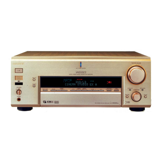
Parts Identification The items are arranged in alphabetical order. Refer to the pages indicated in parentheses ( ) for details. Main unit 1 23 2CH qg (30, 32) 2ND ROOM eh (29) 6.1CH indicator ql 6.1CH DECODING qk (33, 50) A.F.D. -
Page 6: Hooking Up The Components
Hooking Up the Components Required cords Before you get started • Turn off the power to all components before making any connections. • Do not connect the AC power cord until all of the connections are completed. • Be sure to make connections firmly to avoid hum and noise. •... -
Page 7: Antenna Hookups
Antenna hookups ANTENNA COAXIAL DIGITAL /SACD OPTICAL ND/DAT OPTICAL /B-Y MD/DAT OPTICAL /R-Y TV/SAT OPTICAL PHONO DVD/LD OPTICAL /SACD COAXIAL FRONT SURROUND CENTER DVD/LD COAXIAL SIGNAL GND ASSIGNABLE MULTI CHANNEL INPUT 2 Notes on antenna hookups • To prevent noise pickup, keep the AM loop antenna away from the receiver and other components. -
Page 8: Audio Component Hookups
Audio component hookups For details on the required cords (A – F), see page 6. Note on audio component hookups If your turntable has a ground wire, connect it to the U SIGNAL GND terminal. MD or DAT deck INPUT OUTPUT LINE LINE Turntable... -
Page 9: Video Component Hookups
Video component hookups COMPONENT VIDEO ANTENNA COAXIAL DIGITAL /SACD OPTICAL ND/DAT OPTICAL MD/DAT OPTICAL TV/SAT OPTICAL PHONO DVD/LD OPTICAL /SACD COAXIAL To the front DVD/LD panel COAXIAL SIGNAL GND ASSIGNABLE Camcorder or video game * You can display the SET UP, SURROUND, LEVEL, EQ parameters and selected sound field by pressing ON SCREEN. -
Page 10: Digital Component Hookups
You can also connect an LD player with an RF OUT jack via an RF demodulator, like the Sony MOD-RF1 (not supplied). You can select the input mode for your digital components. See “INPUT MODE” on page 27. - Page 11 Connect the digital output jacks of your MD or DAT deck to the receiver’s digital input jack and connect the digital input jacks of your MD or DAT deck to the receiver’s digital output jack. These connections allow you to make digital recordings of TV broadcasts, etc. MD or DAT deck DIGITAL OPTICAL...
-
Page 12: Multi Channel Input Hookups
Multi channel input hookups Although this receiver incorporates a multi channel decoder, it is also equipped with multi channel input jacks. These connections allow you to enjoy multi channel software encoded in formats other than Dolby Digital and DTS. If your DVD player is equipped with multi channel output jacks, you can connect them directly to the receiver to enjoy the sound of the DVD player’s multi channel decoder. -
Page 13: Other Hookups
SUB WOOFER SUB WOOFER MULTI CHANNEL INPUT 2 MULTI CHANNEL INPUT 1 • If you have a Sony CD changer with a COMMAND MODE selector If your CD changer’s COMMAND MODE compatible selector can be set to CD 1, CD 2, or CD 3, be sure to set the command mode to “CD 1”... -
Page 14: Connecting The Ac Power Cord
Other hookups (continued) 2ND ROOM hookup You can use the 2ND ROOM OUT jacks to output the audio/video signals of the selected component to a stereo amplifier located in another room (see page 29). Setting the voltage selector If your receiver has a voltage selector on the rear panel, check that the voltage selector is set to the local power supply voltage. - Page 15 Notes • (Models of area code E only) Two AC power cords are supplied. Use either AC power cord that fits your wall outlet. • We recommend that you connect this unit directly to a wall outlet. If you must use a multi-outlet tap, or extension cord, be sure to use one capable of handling high current (at least 10 A) or one designed for office use.
-
Page 16: Hooking Up And Setting Up The Speaker System
Hooking Up and Setting Up the Speaker System Speaker system hookup Required cords A Speaker cords (not supplied) (–) B Monaural audio cord (not supplied) Black C Audio cord (not supplied) White (L) Red (R) Active sub woofer INPUT AUDIO VIDEO 2 VIDEO 1 S2 VIDEO... - Page 17 Tips • You can connect an active sub woofer to either of the two jacks. The remaining jack can be used to connect a second active sub woofer. As the active sub woofer does not have the directivity, you can place it wherever you want.
-
Page 18: Performing Initial Setup Operations
Speaker system hookup (continued) Speaker impedance To enjoy multi channel surround, connect front, center, surround, and surround back speakers with a nominal impedance of 8 ohms or higher, and set the IMPEDANCE SELECTOR to “8 ”. Check the operating instructions supplied with your speakers if you’re not sure of their impedance. -
Page 19: Multi Channel Surround Setup
Performing initial setup operations Before using your receiver for the first time, adjust SET UP parameters so that the receiver correspond to your system. For the adjustable parameters, see the table on page 84. See pages 19–24 for speaker settings and pages 50–52 for other settings. - Page 20 Multi channel surround setup (continued) Initial settings Parameter FRONT SP CENTER SP SURROUND SP SURR BACK SP SURR BACK L/R SUB WOOFER FRONT CENTER SURROUND SURR BACK SUB WOOFER S.W PHASE DISTANCE UNIT SURR POSI. SURR HEIGHT SURR BACK HGT. FRONT SP >* CENTER SP >* SURROUND SP >*...
- Page 21 x Surround back speaker size (SURR BACK) • If you connect a large speaker that will effectively reproduce bass frequencies, select “LARGE”. Normally, select “LARGE”. However, if the front speakers are set to “SMALL”, you cannot set the surround back speaker to “LARGE”.
- Page 22 Multi channel surround setup (continued) x Surround speaker distance (SURROUND) Set the distance from your listening position to the surround speakers. Surround speaker distance should be set from a distance equal to the front speaker distance (A on page 19) to a distance 4.5 meters closer to your listening position (C on page 19).
- Page 23 x Surround speaker position (SURR POSI.)* This parameter lets you specify the location of your surround speakers for proper implementation of the Digital Cinema Sound surround modes in the “VIRTUAL” sound fields. Refer to the illustration below. • Select “SIDE” if the location of your surround speakers corresponds to section A.
- Page 24 Multi channel surround setup (continued) The surround/surround back speaker position parameter is designed specifically for implementation of the Digital Cinema Sound modes in the “VIRTUAL” sound fields. With the Digital Cinema Sound modes, speaker position is not as critical as other modes. All of the modes in the “VIRTUAL”...
-
Page 25: Checking The Connections
Adjusting the speaker level Use the remote while seated in your listening position to adjust the level of each speaker. Note The receiver incorporates a new test tone with a frequency centered at 800 Hz for easier speaker level adjustment. Press ?/1 to turn on the receiver. -
Page 26: Basic Operations
Basic Operations Selecting the component FUNCTION control Turn FUNCTION control to select the component you want to use. To select Rotate to light VIDEO 1 or VIDEO 2 Camcorder or VIDEO 3 video game DVD or LD player DVD/LD TV or satellite tuner TV/SAT Tape deck TAPE... -
Page 27: Input Mode
INPUT MODE Press INPUT MODE to select the input mode for your digital components. You can also select the COAXIAL or OPTICAL audio input of other functions assigned by AUDIO SPLIT. Each time you press the button, the input mode of the currently selected component switches. -
Page 28: Selecting The 7.1 Channel Mode
“Surround back speaker single or double (SURR BACK L/R)” to “YES”. For details on the setting, see pages 20–21. Note No sound is output from the SPEAKERS SURR BACK terminals. STR-VA555ES Stereo amplifier PRE OUT... -
Page 29: Listening To The Sound In Another Room
Listening to the sound in another room 1 / u – – – 2ND ROOM OUT AUDIO IN Stereo amplifier SPEAKERS You can select the analog audio signals for output to a stereo amplifier in another room. For details on the connection, see page 13. Press 2ND ROOM. -
Page 30: Enjoying Surround Sound
DCS is the concept name of the surround technology for home theater developed by Sony. DCS uses the DSP (Digital Signal Processor) technology to reproduce the sound characteristics of an actual cinema cutting studio in Hollywood. - Page 31 “VIRTUAL MATRIX 6.1” playback function (page 33). • SEMI C.STUDIO EX A reproduces the sound characteristics of Sony Pictures Entertainment’s classic editing studio. • SEMI C.STUDIO EX B reproduces the sound characteristics of Sony Pictures Entertainment’s mixing studio which is one of the most up-to- date facilities in Hollywood.
- Page 32 Selecting a sound field (continued) x CHURCH Reproduces the acoustics of a stone church. x OPERA HOUSE Reproduces the acoustics of an opera house. x JAZZ CLUB Reproduces the acoustics of a jazz club. x DISCO/CLUB Reproduces the acoustics of a discotheque/ dance club.
- Page 33 NIGHT MODE Allows you to retain a theater like environment, at low volume levels even late at night. Even at a low volume level, you can clearly hear the dialogues and adjust the volume in small steps. This function can be used with other sound field (pages 30–32).
-
Page 34: Dolby Digital Ex
Discrete 6.1 channel signals are DVD specific signals not used in movie theaters. Set 6.1 Channel Encoding to “AUTO” to play the discrete 6.1 channel signals. Set 6.1 Channel Decoding to “ON” to activate Sony DCMD and play 6.1 channel signals equivalent to those that would be used in a movie theater. -
Page 35: Understanding The Multi Channel Surround Displays
Understanding the multi channel surround displays PRO LOGIC L.F.E. 1 SW: Lights up when sub woofer selection is set to “YES” and the receiver detects that the disc being played back does not contain the LFE channel signal. While this indicator lights up, the receiver creates a sub woofer signal based on the low frequency components of the front channels. - Page 36 Understanding the multi channel surround displays (continued) qa MPEG: Lights up when MPEG signals are input. Note Only the front 2 channels are compatible with MPEG format. Multi channel surround sound is downmixed and output from the front 2 channels. qs DTS: Lights up when DTS signals are input.
-
Page 37: Customizing Sound Fields
Customizing sound fields By adjusting the surround parameters and the equalization of the front, center, surround, and surround back speakers, you can customize the sound fields to suit your particular listening situation. Once you customize a sound field, the changes are stored in the memory indefinitely. -
Page 38: Dts Neo:6
Customizing sound fields (continued) 2ch decode mode (2CH MODE) Lets you specify the type of decoding for the 2 channel source. This receiver incorporates with Dolby Surround Pro Logic II, and DTS Neo:6. Each of these has movie mode and music mode, and the receiver can reproduce the 2 channel sound in 5.1 channel through Dolby Surround Pro Logic II, or 6 channel through... -
Page 39: Adjusting The Level Parameters
Front reverberation (FRONT REVERB) This parameter can be used when “D.CONCERT HALL A, B” is selected. This parameter lets you adjust the amount of reverberations to add to the front signals according to the original reverberations in the source. • To increase front reverberations, select “WET”. •... - Page 40 Customizing sound fields (continued) Initial settings Parameter TEST TONE* PHASE NOISE* PHASE AUDIO* FRONT L__I__R SURROUND L__I__R SUR.BACK L__I__R CENTER LEVEL SURROUND LEVEL SUR.BACK LEVEL S.WOOFER LEVEL LFE MIX LEVEL D.RANGE COMP. * One of these parameters appears depending on the test tone mode (T.TONE) parameter in the SET UP menu (page 52).
-
Page 41: Adjusting The Equalizer
Dynamic range compressor (D. RANGE COMP.) Lets you compress the dynamic range of the sound track. This may be useful when you want to watch movies at low volumes late at night. We recommend using the “MAX” setting. • To reproduce the sound track with no compression, select “OFF”. - Page 42 Adjusting the equalizer (continued) Front speaker bass adjustment (Gain/Frequency) Lets you adjust the gain and frequency of bass. Front speaker midrange adjustment (Gain/Frequency) Lets you adjust the gain and frequency of midrange. Front speaker midrange bandwidth Lets you adjust the width of the midrange band. •...
-
Page 43: Receiving Broadcasts
Receiving Broadcasts Before receiving broadcasts, make sure you have connected FM and AM antennas to the receiver (see page 7). Storing FM stations automatically (AUTOBETICAL) (Models of area code CEL only) This function lets you store up to 30 FM and FM RDS stations in alphabetical order without redundancy. -
Page 44: Automatic Tuning
Direct tuning (continued) If you’ve tuned in an AM station, adjust the direction of the AM loop antenna for optimum reception. Repeat steps 2 to 5 to receive another station. Tips • If you do not remember the precise frequency, press TUNING + or TUNING –... -
Page 45: Presetting Radio Stations
Presetting radio stations Rotate FUNCTION to select TUNER. The last received station is tuned in. Tune in the station that you want to preset using Direct Tuning (page 43) or Automatic Tuning (page 44). Press MEMORY. “MEMORY” appears in the display for a few seconds. -
Page 46: Using The Radio Data System (Rds)
Using the Radio Data System (RDS) (Models of area code CEL only) This receiver also allows you to use RDS (Radio Data System), which enables radio stations to send additional information along with the regular program signal. You can use the following convenient RDS features: –... - Page 47 Description of program types Program type Description indication News News programs Current Affairs Topical programs that expand on current news Information Programs offering information on a wide spectrum of subjects, including consumer affairs and medical advice Sport Sports programs Education Educational programs, such as “how-to”...
-
Page 48: Other Operations
Other Operations Naming preset stations and program sources You can enter a name of up to 8 characters for preset stations and program sources. These names (for example, “VHS”) appear in the receiver’s display when a station or program source is selected. Note that no more than one name can be entered for each preset station or program source. -
Page 49: Using The Sleep Timer
Notes • You cannot record a digital audio signal using a component connected to the analog TAPE OUT or MD/DAT OUT jacks. To record a digital audio signal, connect a digital component to the DIGITAL MD/DAT OUT jacks. • Sound adjustments do not affect the signal output from the TAPE OUT or MD/DAT OUT jacks. -
Page 50: Adjustments Using The Set Up Button
Adjustments using the SET UP button The SET UP button allows you to make the following adjustments. Press SET UP. Press the cursor buttons ( select the parameter you want to adjust. Turn the jog dial to select the setting you want. - Page 51 “PCM”. x CONTROL A1 auto function (AUTO FUNCTION) Lets you switch the function of this receiver to the Sony components connected via CONTROL A1 cords (see page 13) automatically when the connected component is set to play mode. continued...
- Page 52 (COMMAND MODE) Lets you select the command mode of the remote. Change the command mode when you use 2 Sony receivers in the same room. x Test tone mode (T.TONE) Lets you select the test tone output mode (page 25).
-
Page 53: Control A1 Control System
The CONTROL A1 control system has been updated to the CONTROL A1 which is the standard system in the Sony 300 disc CD changer and other recent Sony components. Components with CONTROL A1 jacks are compatible with components with CONTROL A1 , and can be connected to each other. -
Page 54: Basic Functions
In this case, use the connecting cord for your connection. When using a commercially available cord, use a monaural (2P) mini-plug cord less than 2 meters long, with no resistance (like the Sony RK-G69HG). Basic Functions The CONTROL A1... -
Page 55: Operations Using The Remote
Operations using the remote Before you use your remote Inserting batteries into the remote Insert three LR6 (size-AA) alkaline batteries with the + and – properly oriented in the battery compartment. When using the remote, point it at the remote sensor receiver. -
Page 56: Location Of Parts And Basic Remote Operations
Before you use your remote (continued) Setting up the remote At the time of shipping, the remote has not been customized to your receiver yet. Before you use the remote for the first time, do the procedure below to set up the remote so that it can control your receiver properly. -
Page 57: Parts Description
Parts Description 1 Display window The current status of the selected component or a list of selectable items appears here. Note Characters other than letters of the alphabet or numbers may be displayed incorrectly on the remote, even if they appear correctly in the display window on the main unit. - Page 58 Location of parts and basic remote operations (continued) qa DIMMER button The function of this button is same as the DIMMER button on the receiver. See page qs AUDIO SPLIT button The function of this button is same as the AUDIO SPLIT button on the receiver.
- Page 59 “Programming the remote” on page 66. If you press the ?/1 switch (2) at the same time, it will turn off the main component and other Sony audio/video components (SYSTEM STANDBY). Note The function of the AV ?/1 switch changes automatically each time you press FUNCTION (4).
- Page 60 Table of buttons used to control each component When you program the remote to control the following Sony or non-Sony components, you can use the buttons on the remote that are marked with circles. Note, however, that some buttons may not operate your component.
- Page 61 Table of operations that appear when you press the SUB button Press SUB to display a list of operations that the corresponding buttons are not found on the remote. The contents of the lists will vary according to the currently selected component. The following table shows the items in each list and the function of each item.
- Page 62 Location of parts and basic remote operations (continued) Component Item(s) VIDEO CD TIME player INDEX + INDEX – CD Player DISC TRACK CONTINUE Selects Continuous Play. SHUFFLE PROGRAM REPEAT MD deck DISPLAY CONTINUE Selects Continuous Play. SHUFFLE PROGRAM REPEAT MENU(EDIT)/ Selects editing operation CLEAR Tape deck A-REC...
- Page 63 “SIDE A/B” appears for non-Sony LD players. b) Only with Sony TVs with the picture-in-picture function. c) Only with Sony TVs that supports the wide-picture mode. d) Only with the Sony CD changer. Note If you have programmed the remote to control non- Sony components, note the following: –...
-
Page 64: Using The Lists
Using the lists Chart of lists See the treelike chart below for the list hierarchy. Details on how to access each list is given from page 65. Some items have sub-lists that appear when you press SUB (see pages 61–62). VIDEO1 VIDEO2 VIDEO3... -
Page 65: Selecting A Component
Selecting a component Basic procedure for selecting a component Do the procedure below to select a component from the function list. Press FUNCTION. The function list appears. The items in the list correspond with the jacks on the receiver. Move the easy scroll key to select a component from the list, then press the key to enter the selection. -
Page 66: Programming The Remote
Using the lists (continued) If you selected a Sony CD changer Move the easy scroll key. The DISC MEMO list appears. Move the easy scroll key to select a disc, then press the key to enter the selection. Start playback. - Page 67 (“Kenwood”, for example), then press the key to enter the selection. When programming the remote to control Sony component Select “Sony.” Programming is now completed. To cancel programming Move the easy scroll key to select “Exit” or “Cancel”...
- Page 68 Using the lists (continued) Move the easy scroll key to select “MACRO1” (or “MACRO2”), then press the key to enter the selection. The program list appears. Move the easy scroll key to select the macro step number (“1-NO SET” for example) then press the key to enter the selection.
- Page 69 2 Move the easy scroll key to select “NO SET”, then press the key to enter selection. To turn off all Sony components (SYSTEM STANDBY) 1 In step 4, move the easy scroll key to select “Common”, then press the key to enter selection.
-
Page 70: Learning The Commands Of Your Components
Using the lists (continued) Learning the commands of your components By using the Learning function, it is possible for this commander to perform learned operations. Setting remote control codes that are not stored in the commander When a remote control code is not one of the presets stored in the commander, it is possible for the commander to learn the code using the Learning function. - Page 71 CD in each slot of a CD changer* from the receiver. * Appears only when you have selected a Sony CD changer (5, 50, 200, 300, or 400 discs) connected to the receiver using the CONTROL A1 cable.
- Page 72 • You can download the data only from the Sony CD changer (5, 50, 200, 300, or 400 discs) connected to the receiver using the CONTROL A1 cable.
- Page 73 Adjusting the level parameters Press SET UP. The set up list appears. Move the easy scroll key to select “RECEIVER”, then press the key to enter the selection. The RECEIVER list appears. Move the easy scroll key to select “LEVEL”, then press the key to enter the selection.
- Page 74 Notes • Switching to VIDEO 1–4 input may not be automatic on all Sony TVs. This is because some TVs cannot receive remote control codes immediately after being turned on. • When you select “(Off)” in step 4, the TV input does not switch.
- Page 75 Switching the COMMAND MODE You can switch the command mode (AV SYSTEM1 or AV SYSTEM2) of the remote. If the command mode of the receiver and the remote is different, you cannot use the remote to operate the receiver. Press SET UP. The set up list appears.
-
Page 76: Additional Information
If you have any question or problem concerning your receiver, please consult your nearest Sony dealer. Troubleshooting If you experience any of the following... - Page 77 There is no sound from one of the front speakers. • Connect a pair of headphones to the PHONES jack to verify that sound is output from the headphones (see page 28). If only one channel is output from the headphones, the component may not be connected to the receiver correctly.
- Page 78 Troubleshooting (continued) Recording cannot be done. • Check that the components are connected correctly. • Select the source component with FUNCTION control. • When recording from a digital component, make sure the INPUT MODE is set to ANALOG 2CH FIXED (see page 27) before recording with a component connected to the analog MD/DAT or TAPE terminals.
-
Page 79: Specifications
• Make sure you select the correct function on the remote. • When you operate a programmed non-Sony component, the remote may not function properly depending on the model and the make of the component. - Page 80 Specifications (continued) 1) Measured under the following conditions: Area code CN, CEL 2) Measured under the following conditions: Area code 3) Depending on the sound field settings and the source, there may be no sound output. Frequency response PHONO CD/SACD, TAPE, MD/DAT, TV/SAT, DVD/LD, VIDEO 1, 2, Inputs (Analog)
- Page 81 AM tuner section Tuning range Models of area code E With 10-kHz tuning scale: 530 – 1610 kHz With 9-kHz tuning scale: 531 – 1602 kHz Models of area code CN, CEL With 9-kHz tuning scale: 531 – 1602 kHz Antenna Loop antenna Usable sensitivity...
-
Page 82: Tables Of Settings Using Surround, Level, Eq, And Set Up Buttons
Tables of settings using SURROUND, LEVEL, EQ, and SET UP buttons You can make various settings using the LEVEL, SURROUND, EQ, SET UP buttons, jog dial, and cursor buttons. The tables below show each of the settings that these buttons can make. Press Press SURROUND... - Page 83 Press Press to select FRONT BASS GAIN FRONT BASS FREQUENCY FRONT MID GAIN FRONT MID FREQUENCY FRONT MID BANDWIDTH FRONT TREBLE GAIN FRONT TREBLE FREQUENCY CENTER BASS GAIN CENTER BASS FREQUENCY CENTER MID GAIN CENTER MID FREQUENCY CENTER MID BANDWIDTH CENTER TREBLE GAIN CENTER TREBLE FREQUENCY SURROUND BASS GAIN...
- Page 84 Tables of settings using SURROUND, LEVEL, EQ, and SET UP buttons (continued) Press Press SET UP FRONT SP CENTER SP SURROUND SP SURR BACK SP SURR BACK L/R SUB WOOFER FRONT CENTER SURROUND SURR BACK SUB WOOFER S.W PHASE DISTANCE UNIT SURR POSI.
-
Page 85: Adjustable Parameters For Each Sound Field
Adjustable parameters for each sound field The adjusted SURROUND parameters are stored in each sound field. The adjusted LEVEL parameters are applied to all the sound fields. < DECODING MODE A.F.D. AUTO NORMAL SURROUND CINEMA STUDIO EX A CINEMA STUDIO EX B CINEMA STUDIO EX C SEMI C.STUDIO EX A SEMI C.STUDIO EX B... - Page 86 Adjustable parameters for each sound field (continued) A.F.D. NORMAL SURROUND CINEMA STUDIO EX A CINEMA STUDIO EX B CINEMA STUDIO EX C SEMI C.STUDIO EX A SEMI C.STUDIO EX B SEMI C.STUDIO EX C NIGHT THEATER MONO MOVIE STEREO MOVIE V.MULTI DIMENSION VIRTUAL MULTI REAR V.SEMI M.DIMENSION...
- Page 87 A.F.D. NORMAL SURROUND CINEMA STUDIO EX A CINEMA STUDIO EX B CINEMA STUDIO EX C SEMI C.STUDIO EX A SEMI C.STUDIO EX B SEMI C.STUDIO EX C NIGHT THEATER MONO MOVIE STEREO MOVIE V.MULTI DIMENSION VIRTUAL MULTI REAR V.SEMI M.DIMENSION VIRTUAL ENHANCED A VIRTUAL ENHANCED B D.CONCERT HALL A...
- Page 88 Adjustable parameters for each sound field (continued) A.F.D. NORMAL SURROUND CINEMA STUDIO EX A CINEMA STUDIO EX B CINEMA STUDIO EX C SEMI C.STUDIO EX A SEMI C.STUDIO EX B SEMI C.STUDIO EX C NIGHT THEATER MONO MOVIE STEREO MOVIE V.MULTI DIMENSION VIRTUAL MULTI REAR V.SEMI M.DIMENSION...
- Page 89 < A.F.D. NORMAL SURROUND CINEMA STUDIO EX A CINEMA STUDIO EX B CINEMA STUDIO EX C SEMI C.STUDIO EX A SEMI C.STUDIO EX B SEMI C.STUDIO EX C NIGHT THEATER MONO MOVIE STEREO MOVIE V.MULTI DIMENSION VIRTUAL MULTI REAR V.SEMI M.DIMENSION VIRTUAL ENHANCED A VIRTUAL ENHANCED B D.CONCERT HALL A...
- Page 92 Sony Corporation Printed in Malaysia...