Table of Contents
Advertisement
SERVICE MANUAL
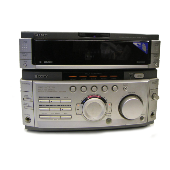
This set is the tuner and amplifier
section in MHC-VX700AV.
Amplifier section
The following measured at AC 120, 220, 240V 50/60 Hz
DIN power output (Rated) (FRONT)
120 + 120W (6 Ω at 1kHz DIN)
Continuous RMS power output (Reference)
FRONT SPEAKER: 150 + 150W
(6 Ω at 1kHz, 10% THD)
CENTER SPEAKER: 60W
(8 Ω at 1kHz, 10% THD)
REAR SPEAKER: 40 + 40W
(8 Ω at 1kHz, 10% THD)
Inputs
MD/VIDEO 1 IN (phono jacks): voltage
450/250mV, impedance 47kΩ
AV INPUT AUDIO (phono jacks): voltage
250mV, impedance 47kΩ
MIX MIC 1/2 (phone jack): sensitivity 1mV,
impedance 10kΩ
Output
MD/VIDEO 1 OUT (phono jacks): voltage
450/250mV, impedance 1kΩ
PHONES (stereo phone jack): accepts
headphones of 8Ω or more.
FRONT SPEAKER:
accepts impedance of 6 to 16Ω
CENTER SPEAKER:
accepts impedance of 8 to 16Ω
REAR SPEAKER:
accepts impedance of 8 to 16Ω
SUPER WOOFER:
Voltage 1V, impedance 1kΩ
Tuner section
FM stereo, FM/AM superheterodyne tuner
FM tuner section
Tuning range
87.5 – 108.0MHz
Antenna terminals
75Ω unbalanced
Intermediate frequency
10.7MHz
AM tuner section
MICROFILM
STR-VX700
SPECIFICATIONS
Tuning range
Thai models:
Other models:
Intermediate frequency
Antenna
General
Power requirements
Thai models:
Other models:
Power consumption
Dimensions (w/h/d)
Mass
Design and specifications are subject to change without notice.
FM STEREO/FM-AM RECEIVER
E Model
531 – 1,602kHz (with the AM tuning
interval set at 9kHz)
530 – 1,710kHz (with the AM tuning
interval set at 10kHz)
MW: 531 – 1,602kHz (with the MW tuning
interval set at 9kHz)
530 – 1,710kHz (with the MW tuning
interval set at 10kHz)
SW: 5.95 – 17.90MHz (with the SW tuning
interval set at 5kHz)
450kHz
AM loop antenna External antenna terminal
220V AC, 50/60Hz
120V, 220V or 230 – 240V AC, 50/60Hz
Adjustable with voltage selector
340W
Approx. 288 × 205 × 375mm
Approx. 8.7kg
Advertisement
Table of Contents

Related Manuals for Sony STR-VX700


Summary of Contents for Sony STR-VX700
- Page 1 STR-VX700 SERVICE MANUAL E Model This set is the tuner and amplifier section in MHC-VX700AV. SPECIFICATIONS Amplifier section Tuning range Thai models: 531 – 1,602kHz (with the AM tuning The following measured at AC 120, 220, 240V 50/60 Hz interval set at 9kHz) DIN power output (Rated) (FRONT) 120 + 120W (6 Ω...
-
Page 2: Table Of Contents
COMPONENTS IDENTIFIED BY MARK ! OR DOTTED LINE WITH MARK ! ON THE SCHEMATIC DIAGRAMS AND IN THE PARTS LIST ARE CRITICAL TO SAFE OPERATION. REPLACE THESE COMPONENTS WITH SONY PARTS WHOSE PART NUMBERS APPEAR AS SHOWN IN THIS MANUAL OR IN SUPPLEMENTS PUBLISHED BY SONY. -
Page 3: General
SECTION 1 GENERAL Front Panel qj qh ql m – button 1 MOVIE button w; NON-STOP button 2 MUSIC button 3 GAME button wa EDIT button 4 PLACE button ws FLASH button wd PLAY MODE button 5 P FILE button wf REPEAT button 6 EFFECT ON/OFF button 7 OPEN/CLOSE button... - Page 4 Rear Panel 1 SYSTEM CONTROL jack 2 ANTENNA terminal 3 CENTER SPEAKER terminal 4 REAR SPEAKER terminal 5 MONITOR OUT jack 6 FRONT SPEAKER terminal 7 MD/VIDEO 1 jack...
-
Page 5: Disassembly
SECTION 2 DISASSEMBLY Note: Follow the disassembly procedure in the numerical order given. 2-1. SLIDING PANEL ASSEMBLY 4 Flat type cable (19 core) Slide mechanism 1 Push the OPEN/CLOSE button to open the Sliding panel assembly. × 2 Screw (BVTP 3 5 Sliding panel assembly 3 Holder level 2-2. -
Page 6: Service Mode
SECTION 3 SERVICE MODE Connections and Operations When Used Alone Normally, use the unit connected to the HTC-VX500 as follows. Basically, when servicing the unit, connect the unit as follows. HTC-VX500 UNIT SYSTEM CONTROL 17P AC IN Even when not connected to the HTC-VX500, the unit can operate alone as it mounts a power supply (some functions will however not be available). - Page 7 LED and Fluorescent Indicator Tube All Lit, Key Check Mode (Do not connect the HTC-VX500.) Procedure: Press 1/1 button to turn the set ON. Press the OPEN/CLOSE button to open the sliding panel. Press three buttons DELAY , ENTER/NEXT , and DISPLAY/DEMO simultaneously. LEDs and fluorescent indicator tube are all turned on.
- Page 8 • When operations end abnormally: Display of fluorescent display tube Display Main Cause NO DISC ERR DISC 1 is NO DISC from the beginning FOCUS1 ERR Focus is not imposed properly FOCUS2 ERR The focus deviated several times after the disc rotated normally GFS ERR GFS ERROR FBIAS ERR...
-
Page 9: Diagrams
SECTION 4 DIAGRAMS PANEL Aging Mode 4-1. CIRCUIT BOARDS LOCATION This mode is used for opening and closing the sliding panel continuously. Setting the aging mode : With the set at standby condition, press FLASH button, ENTER/NEXT button and STEREO/MONO button together. PRIMARY board The aging will start and sliding panel will follow aging sequence as described below. -
Page 10: Block Diagrams
STR-VX700 4-2. BLOCK DIAGRAMS MAIN SECTION VIDEO IC111(1/2) VOLUME IC111(2/2) L-CH SELECT R-CH(CD R) SWITCH MUTE MICON MD/V1 R-CH(PB R) Q183 INTERFACE CN101 POWER R-CH SYSTEM IC113(2/2) R-CH MUTE SECTION CONTROL 32 34 R-CH(REC R) HTC-VX500 DBFB SELECTOR IIC DATA... -
Page 11: Power Section
STR-VX700 POWER SECTION J781 RY781 VIDEO VIDEO OUT SUPER WOOFER POWER AMP TB201 IC4001(1/2) RY741 C OUT CENTER SPEAKER OVER LOAD POWER AMP Q4002 IC4001(2/2) S OUT REAR SPEAKER OVER LOAD D746 Q4052 R-CH R-CH MAIN D761 SECTION POWER AMP... - Page 12 Waveforms THIS NOTE IS COMMON FOR PRINTED WIRING BOARDS AND SCHEMATIC DIAGRAMS. DISPLAY Section (In addition to this, the necessary note is printed in each block.) For schematic diagrams. For printed wiring boards. 5.5Vp-p Note: Note: • All capacitors are in µF unless otherwise noted. pF: µµF •...
-
Page 13: Printed Wiring Board Main Section
STR-VX700 4-3. PRINTED WIRING BOARD MAIN SECTION • Refer to page 9 for Circuit Boards Location. • Semiconductor Location Ref. No. Location D101 B-11 D102 B-11 D131 D742 D743 F-10 D746 F-11 D751 F-11 D752 E-10 D761 E-12 D781 G-10... -
Page 14: Schematic Diagram Main (1/2) Section
STR-VX700 4-4. SCHEMATIC DIAGRAM MAIN (1/2) SECTION • Refer to page 13 for Printed Wiring Board.. • Refer to page 28 to 29 for IC Block Diagrams. TO HTC-VX500 560k 560k 560k 560k 2.7k 2.7k... -
Page 15: Schematic Diagram Main (2/2) Section
STR-VX700 4-5. SCHEMATIC DIAGRAM MAIN (2/2) SECTION • Refer to page 13 for Printed Wiring Board. • Refer to page 29 for IC Block Diagrams. 1.2k 2SC2958 1.5 k Q854 2SA124ES 1000 R857 Q855 2SC2958L Q854, 855 RELAY SWITCH VG REG The components identified by mark ! or dotted line with mark ! are critical for safety. -
Page 16: Schematic Diagram Power Amp Section
STR-VX700 4-6. SCHEMATIC DIAGRAM POWER AMP SECTION 100V 100V STK4241MK2 100V STK4241MK2 The components identified by mark ! or dotted line with mark ! are critical for safety. Replace only with part number specified. -
Page 17: Printed Wiring Board Power Amp Section
STR-VX700 4-7. PRINTED WIRING BOARD POWER AMP SECTION • Refer to page 9 for Circuit Boards Location. TH MODEL... -
Page 18: Schematic Diagram Display Section
STR-VX700 4-8. SCHEMATIC DIAGRAM DISPLAY SECTION • Refer to page 30 for IC Block Diagrams. • Refer to page 12 for Waveform. EA MODEL R514 TH MODEL EA,HK,MY, SP MODEL MY,SP,HK, TH MODEL... -
Page 19: Printed Wiring Board Display Section
STR-VX700 4-9. PRINTED WIRING BOARD DISPLAY SECTION • Refer to page 9 for Circuit Boards Location. • Semiconductor Location Ref. No. Location D501 D502 D504 D505 D506 R514 EA MODEL D507 MY,SP,TH, HK MODEL D509 D511 TH MODEL D512 D513... -
Page 20: Schematic Diagram Sliding Panel Section
STR-VX700 4-10. SCHEMATIC DIAGRAM SLIDING PANEL SECTION • Refer to page 30 for IC Block Diagrams. -
Page 21: Printed Wiring Board Sliding Panel Section
STR-VX700 4-11. PRINTED WIRING BOARD SLIDING PANEL SECTION • Refer to page 9 for Circuit Boards Location. -
Page 22: Schematic Diagram Surround Amp Section
STR-VX700 4-12. SCHEMATIC DIAGRAM SURROUND AMP SECTION The components identified by mark ! or dotted line with mark ! are critical for safety. Replace only with part number specified. -
Page 23: Printed Wiring Board Surround Amp Section
STR-VX700 4-13. PRINTED WIRING BOARD SURROUND AMP SECTION • Refer to page 9 for Circuit Boards Location. -
Page 24: Printed Wiring Board Trans Section
STR-VX700 4-14. PRINTED WIRING BOARD TRANS SECTION • Refer to page 9 for Circuit Boards Location. T901 EA,HK,MY,SP MODEL F878 F879 EA,HK,MY,SP MODEL EA,HK,MY,SP MODEL EA,HK,MY, TH MODEL SP MODEL... -
Page 25: Schematic Diagram Trans Section
STR-VX700 4-15. SCHEMATIC DIAGRAM TRANS SECTION EA,HK,MY,SP MODEL F878 T2.5A 250V F879 T2.5A 250V EA,HK,MY,SP MODEL T8AL T8AL The components identified by mark ! or dotted line with mark ! are critical for safety. Replace only with part number specified. -
Page 26: Schematic Diagram Av/Mic Section
STR-VX700 4-16. SCHEMATIC DIAGRAM AV/MIC SECTION • Refer to page 30 for IC Block Diagrams. L6301 C6304... -
Page 27: Printed Wiring Board Av/Mic Section
STR-VX700 4-17. PRINTED WIRING BOARD AV/MIC SECTION • Refer to page 9 for Circuit Boards Location. -
Page 28: Ic Block Diagrams
4-18. IC BLOCK DIAGRAMS • MAIN BOARD IC300 LV1041M R BPF2 L BPF2 RECT RECT LOGIC LOGIC R BPF1 RECT L BPF1 RECT LOGIC LOGIC RT IN S DC OUT C DC OUT R DC OUT LT IN L DC OUT CONTROL DC CUT V REF... - Page 29 IC851 µPC1237HA OVER LOAD DET MUTE OFFSET DET LATCH/ AUTORESET AC OFF...
- Page 30 • PANEL BOARD IC505 µPD4053BC IC506 BA3833F-E2 RESET RESET 18 RESET B.COM OPEN A.COM REFFERENCE PREF 17 f01 CURRENT C.COM OPEN LINE 16 f02 LINE 15 f03 OPEN BIAS 13 f Bias 12 VCC 11 NC 10 NC • MOTOR BOARD •...
-
Page 31: Ic Pin Function
4-19. IC PIN FUNCTION • IC501 SYSTEM CONTROL (uPD780016AYGF-025-3BA)(PANEL BOARD) Pin No. Pin Name Description Prologic clock output LEVEL A Not used LEVEL B Not used PROLOGIC RLY Prologic relay drive signal output DBFB B2 DBFB level 2 signal output DBFB B1 DBFB level 1 signal output TA MUTE... - Page 32 Pin No. Pin Name Description AV IN AV INPUT (VIDEO 2) switch input SENSOR IN Sliding (panel) sensor signal input SIRCS IN Remote sensor signal input SPEANE RST Spectrum analyzer reset output — — Ground — — SOFT Soft test terminal Audio indicator output MOVIE A MOVIE G...
- Page 33 Pin No. Pin Name Description — Ground MOTOR1 Panel motor control output MOTOR2 PANEL OPEN Panel open switch output PANEL CLOSE Panel close switch output ST. MUTE ST mute signal output STEREO Stereo detection input for tuner TUNED Tuner detection input for tuner Tuner PLL latch output DATA IN Tuner PLL data input...
-
Page 34: Exploded Views
SECTION 5 EXPLODED VIEWS NOTE: • -XX, -X mean standardized parts, so they may • Hardware (# mark) list and accessories and When indicating parts by reference number, have some differences from the original one. packing materials are given in the last of this please include the board name. -
Page 35: Front Panel Section
X-4951-665-1 ESCUTCHEON (L) ASSY * 62 4-932-810-11 CUSHION (FL) X-4949-994-1 ESCUTCHEON (EQ) ASSY * 63 4-900-849-01 HOLDER (FL) 4-962-708-11 EMBLEM (4-A), SONY * 64 1-669-957-11 FRONT AV BOARD 4-951-620-01 SCREW (2.6 × 8), +BVTP 4-900-845-01 BRACKET SLIDER * 59 A-4414-708-A MIC/ECHO BOARD, COMPLETE (EA,HK,MY,SP) -
Page 36: Slide Mechanism Section
5-3. SLIDE MECHANISM SECTION M891 Ref. No. Part No. Description Remarks Ref. No. Part No. Description Remarks 4-900-844-01 LEVEL SLIDER 4-900-864-01 BRACKET TOP 4-951-620-01 SCREW (2.6X8), +BVTP 4-900-847-01 GEAR (2) X-4950-394-2 HOLDER (L) ASSY 3-344-059-01 BELT (L) X-4950-395-2 HOLDER (R) ASSY * 111 1-669-965-11 MOTOR BOARD * 105... -
Page 37: Circuit Boards And Back Panel Section
5-4. CIRCUIT BOARDS AND BACK PANEL SECTION TH MODEL EA, MY, SP MODEL HK MODEL not supplied T901 M901 not supplied Ref. No. Part No. Description Remarks Ref. No. Part No. Description Remarks * 151 A-4419-955-A MAIN BOARD, COMPLETE (EA,HK,MY,SP) 4-970-381-11 FOOT (REAR) * 151 A-4426-816-A MAIN BOARD, COMPLETE (TH) -
Page 38: Electrical Parts List
CONNECTOR DETECTOR FRONT AV SECTION 6 ELECTRICAL PARTS LIST HEADPHONE LOADING PANEL NOTE: • Due to standardization, replacements in the • RESISTORS • Abbreviation parts list may be different from the parts All resistors are in ohms. : Hong Kong model specified in the diagrams or the components METAL: metal-film resistor : Singapore model... - Page 39 LOADING PANEL MAIN Ref. No. Part No. Description Remarks Ref. No. Part No. Description Remarks < DIODE > R661 1-249-429-11 CARBON 1/4W R662 1-249-429-11 CARBON 1/4W D631 8-719-046-39 DIODE SEL5821A-TP15 (GROOVE) R663 1-249-429-11 CARBON 1/4W D632 8-719-046-44 DIODE SEL5221S-TP15 (REW) R665 1-247-843-11 CARBON 3.3K...
- Page 40 MAIN Ref. No. Part No. Description Remarks Ref. No. Part No. Description Remarks C118 1-162-290-31 CERAMIC 470PF C318 1-126-961-11 ELECT 2.2uF C119 1-162-600-11 CERAMIC 0.0047uF 30% C319 1-104-664-11 ELECT 47uF C121 1-126-964-11 ELECT 10uF C320 1-136-173-00 FILM 0.47uF C122 1-162-291-31 CERAMIC 560PF C321 1-161-494-00 CERAMIC...
- Page 41 MAIN Ref. No. Part No. Description Remarks Ref. No. Part No. Description Remarks C806 1-126-964-11 ELECT 10uF D853 8-719-911-19 DIODE 1SS119-25 C807 1-136-165-00 FILM 0.1uF C808 1-136-165-00 FILM 0.1uF < TERMINAL > C809 1-126-943-11 ELECT 2200uF C810 1-126-943-11 ELECT 2200uF * E801 1-537-738-21 TERMINAL, EARTH C815...
- Page 42 MAIN Ref. No. Part No. Description Remarks Ref. No. Part No. Description Remarks R123 1-249-421-11 CARBON 2.2K 1/4W F R375 1-249-437-11 CARBON 1/4W R132 1-249-421-11 CARBON 2.2K 1/4W F R376 1-249-421-11 CARBON 2.2K 1/4W F R134 1-249-435-11 CARBON 1/4W R377 1-249-425-11 CARBON 4.7K 1/4W F...
- Page 43 MAIN MIC/ECHO MOTOR Ref. No. Part No. Description Remarks Ref. No. Part No. Description Remarks < VIBRATOR > < JACK > X301 1-579-952-21 VIBRATOR, CERAMIC 8MHz J6001 1-770-226-11 JACK (LARGE TYPE)(MIX MIC 1) J6002 1-750-733-11 JACK (LARGE TYPE)(MIX MIC 2) ************************************************************** A-4414-708-A MIC/ECHO BOARD, COMPLETE (EA,HK,MY,SP) <...
- Page 44 PANEL Ref. No. Part No. Description Remarks Ref. No. Part No. Description Remarks A-4426-835-A PANEL BOARD, COMPLETE (EA) < DIODE > ************************* A-4417-076-A PANEL BOARD, COMPLETE (HK,MY,SP) D501 8-719-024-99 DIODE 11ES2-NTA2B D502 8-719-911-19 DIODE 1SS119-25 ******************************* A-4417-069-A PANEL BOARD, COMPLETE (TH) D504 8-719-911-19 DIODE 1SS119-25 D505...
- Page 45 PANEL Ref. No. Part No. Description Remarks Ref. No. Part No. Description Remarks R505 1-249-429-11 CARBON 1/4W R566 1-247-807-31 CARBON 1/4W R506 1-249-429-11 CARBON 1/4W R567 1-247-807-31 CARBON 1/4W R507 1-249-441-11 CARBON 100K 1/4W R568 1-247-807-31 CARBON 1/4W R511 1-249-429-11 CARBON 1/4W R569 1-249-407-11 CARBON...
- Page 46 PANEL POWER AMP Ref. No. Part No. Description Remarks Ref. No. Part No. Description Remarks < SWITCH > C937 1-128-560-11 ELECT 22uF 100V C938 1-126-934-11 ELECT 220uF S501 1-762-751-11 SWITCH, TACTILE (EQ 16kHz+) C940 1-128-581-11 ELECT 4.7uF 100V S502 1-762-751-11 SWITCH, TACTILE (NAME IN) C950 1-162-306-11 CERAMIC 0.01uF...
- Page 47 POWER AMP PRIMARY SECONDARY SURR AMP Ref. No. Part No. Description Remarks Ref. No. Part No. Description Remarks R934 1-249-421-11 CARBON 2.2K 1/4W F < FUSE > R935 1-249-421-11 CARBON 2.2K 1/4W F R936 1-249-421-11 CARBON 2.2K 1/4W F ! F874 1-533-949-31 FUSE TIME LAG 8A/250V R937 1-249-429-11 CARBON...
- Page 48 STR-VX700 SURR AMP SURR SPK Ref. No. Part No. Description Remarks Ref. No. Part No. Description Remarks < RESISTOR > < RELAY > R4001 1-249-417-11 CARBON 1/4W F RY781 1-515-622-11 RELAY R4002 1-249-437-11 CARBON 1/4W R4003 1-249-413-11 CARBON 1/4W F <...