
Related Manuals for Sony STR-DG700


Summary of Contents for Sony STR-DG700
- Page 1 2-680-065-11 (1) Multi Channel AV Receiver Operating Instructions STR-DG700 ©2006 Sony Corporation...
-
Page 2: About This Manual
About This Manual • The instructions in this manual are for model STR-DG700. Check your model number by looking at the lower right corner of the front panel. In this manual, models of area code CEL is used for illustration purposes unless stated otherwise. -
Page 3: Table Of Contents
Table of Contents Getting Started Description and location of parts ... 4 1: Installing speakers... 13 2: Connecting speakers ... 14 3a: Connecting the audio components ... 15 3b: Connecting the video components ... 20 4: Connecting the antennas ... 28 5: Preparing the receiver and the remote... -
Page 4: Getting Started
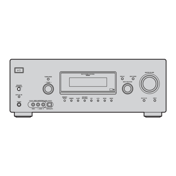
Getting Started Description and location of parts Front panel TUNING MODE – TUNING SPEAKERS (OFF/A/B/A+B) AUTO CAL MIC VIDEO 3 IN/PORTABLE AV IN PHONES VIDEO L AUDIO R DIGITAL(OPT) To remove the cover Press PUSH. When you remove the cover, keep it out of reach from children. - Page 5 Name Function F MULTI CHANNEL Lights up when multi DECODING lamp channel audio is decoded (page 37). G Remote sensor Receives signals from remote commander. H DISPLAY Press to select information displayed on the display (page 63, 67). I INPUT MODE Press to select the input mode when the same components are connected...
- Page 6 About the indicators on the display SP A DIGITAL EX SP B SLEEP OPT COAX SL S SR Name Function A SW Lights up when sub woofer selection is set to “YES” (page 41) and the audio signal is output from the SUB WOOFER jack.
- Page 7 Name Function H MEMORY Lights up when a memory function, such as Preset Memory (page 61), etc., is activated. I A.DIRECT Lights up when ANALOG DIRECT is selected (page 56). J Preset Lights up when using the station receiver to tune in radio stations indicators you have preset.
-
Page 8: Rear Panel
Rear panel DIGITAL DVD IN OPTICAL VIDEO 1 ANTENNA ASSIGNABLE VIDEO 2 TAPE TAPE SA-CD/ COAXIAL SA-CD/CD MD/TAPE A DIGITAL INPUT/OUTPUT section OPTICAL IN/OUT jack COAXIAL IN jack HDMI IN/ MONITOR OUT jack* B VIDEO/AUDIO INPUT/OUTPUT section AUDIO IN/ White (L) OUT jack Red (R) VIDEO IN/... - Page 9 MONITOR OUT jack to a TV monitor (page 22). Remote commander You can use the supplied remote RM-AAP011 to operate the receiver and to control the Sony audio/video components that the remote is assigned to operate. You can also program the remote to control non-Sony audio/video components.
- Page 10 Press to enter the value after selecting a channel, disc or track using the numeric buttons. To enter the value of Sony TV, press TV (Z) and then press ENTER. Press MEMORY to store a station. Press to display options applicable to the entire disc (e.g.
- Page 11 PSX, DVD/VIDEO COMBO, or DVD/HDD COMBO on the TV screen. Then, use the control buttons to perform menu operations. To display the menus of Sony TV, press TV (Z) and then press MENU. L TV CH + /– Press TV (Z) and then press TV CH +/–...
- Page 12 DVD player, Blu-ray disc recorder, PSX, or satellite tuner is displayed on the TV screen. To return to the previous menu of Sony TV, press TV (Z) and then press RETURN/ EXIT O. R Control After pressing AMP (J), buttons...
-
Page 13: 1: Installing Speakers
1: Installing speakers This receiver allows you to use a 6.1 channel system (6 speakers and one sub woofer). Enjoying a 5.1/6.1 channel system To fully enjoy theater-like multi channel surround sound requires five speakers (two front speakers, a center speaker, and two surround speakers) and a sub woofer (5.1 channel). -
Page 14: 2: Connecting Speakers
2: Connecting speakers DVD IN VIDEO 2 IN MONITOR OUT ASSIGNABLE HDMI MONITOR VIDEO IN VIDEO IN VIDEO OUT VIDEO IN VIDEO OUT S-VIDEO S-VIDEO S-VIDEO S-VIDEO S-VIDEO AUDIO IN AUDIO IN AUDIO OUT AUDIO IN FRONT MD/TAPE VIDEO 2 VIDEO 1 MULTI CH IN A Monaural audio cord (not supplied) -
Page 15: 3A: Connecting The Audio Components
3a: Connecting the audio components How to hook up your components This section describes how to hook up your components to this receiver. Before you begin, refer to “Component to be connected” below for the pages which describe how to connect each component. - Page 16 Connecting components with digital audio input/output jacks The following illustration shows how to connect a Super Audio CD player/CD player and an MD deck/tape deck. Super Audio CD player/CD player OPTICAL VIDEO 1 VIDEO 2 TAPE TAPE SA-CD/ COAXIAL A Audio cord (not supplied) B Coaxial digital cord (not supplied) C Optical digital cord (not supplied) MD deck/Tape deck...
- Page 17 Notes on playing a Super Audio CD disc on a Super Audio CD player • No sound is output when you play a Super Audio CD disc on a Super Audio CD player connected to only the SA-CD/CD COAXIAL IN jack on this receiver. When you play a Super Audio CD disc, connect the player to the MULTI CH IN or SA-CD/CD IN jack.
- Page 18 Connecting components with multi channel output jacks If your DVD or Super Audio CD player is equipped with multi channel output jacks, you can connect it to the MULTI CH IN jacks of this receiver to enjoy multi channel sound. Alternatively, the multi channel input jacks can be used to connect an external multi channel decoder.
-
Page 19: Connecting Components With
Connecting components with analog audio jacks The following illustration shows how to connect a component which has analog jacks such as tape deck, etc. Super Audio CD player/CD player DIGITAL OPTICAL VIDEO 1 ANTENNA VIDEO 2 TAPE TAPE SA-CD/ COAXIAL SA-CD/CD CD player, MD deck,... -
Page 20: 3B: Connecting The Video Components
3b: Connecting the video components How to hook up your components This section describes how to hook up your components to this receiver. Before you begin, refer to “Component to be connected” below for the pages which describe how to connect each component. -
Page 21: Component
TV monitor etc., INPUT jack Receiver MONITOR OUT jack Receiver INPUT jack Video component OUTPUT jack Notes • Connect image display components such as a TV monitor or a projector to the MONITOR OUT jack on the receiver. • Turn on the receiver when the video and audio of a playback component are being output to a TV through the receiver. -
Page 22: Tv Monitor
Hooking up a TV monitor The image from a visual component connected to this receiver can be displayed on a TV screen. It is not necessary to connect all the cables. Connect video cords according to the jacks of your components. DIGITAL OPTICAL VIDEO 1... -
Page 23: Dvd Player/Dvd Recorder
Hooking up a DVD player/DVD recorder The following illustration shows how to connect a DVD player/DVD recorder. It is not necessary to connect all the cables. Connect audio and video cords according to the jacks of your components. 1 Connecting audio DVD player DIGITAL OPTICAL... - Page 24 2 Connecting video DIGITAL OPTICAL VIDEO 1 ANTENNA VIDEO 2 TAPE TAPE SA-CD/ COAXIAL SA-CD/CD MD/TAPE A S-video cord (not supplied) B Video cord (not supplied) C Component video cord (not supplied) If you connect a DVD recorder • Be sure to change the factory setting of the VIDEO 1 input button on the remote so that you can use the button to control your DVD recorder.
-
Page 25: Satellite Tuner
Hooking up a satellite tuner The following illustration shows how to connect a satellite tuner. It is not necessary to connect all the cables. Connect audio and video cords according to the jacks of your components. DIGITAL OPTICAL VIDEO 1 ANTENNA VIDEO 2 TAPE... - Page 26 TAPE SA-CD/ COAXIAL A HDMI cable (not supplied) We recommend that you use a Sony HDMI cable. Notes on HDMI connections • The multi/stereo area audio signals of a Super Audio CD are not output. • Turn on the receiver when the video and audio of a playback component are being output to a TV via the receiver.
-
Page 27: Vcr
Hooking up components with analog video and audio jack The following illustration shows how to connect a component which has analog jacks such as a VCR, etc. DIGITAL OPTICAL VIDEO 1 ANTENNA VIDEO 2 TAPE TAPE SA-CD/ COAXIAL SA-CD/CD MD/TAPE To the VIDEO 3 IN/PORTABLE AV IN jacks Camcorder/ video game... -
Page 28: 4: Connecting The Antennas
4: Connecting the antennas Connect the supplied AM loop antenna and FM wire antenna. FM wire antenna (supplied) DIGITAL OPTICAL VIDEO 1 ANTENNA VIDEO 2 TAPE TAPE SA-CD/ COAXIAL SA-CD/CD * The shape of the connector varies depending on the area code of this receiver. Notes •... -
Page 29: 5: Preparing The Receiver And The Remote
5: Preparing the receiver and the remote Connecting the AC power cord Connect the AC power cord to a wall outlet. AC power cord CENTER AC OUTLET – SURROUND BACK – – FRONT A FRONT B EAKERS To the wall outlet * The configuration, shape and number of AC outlets will vary according to the area code of the receiver you purchased. -
Page 30: 6: Selecting The Speaker System
Inserting batteries into the remote Insert two R6 (size-AA) batteries in the RM-AAP011 remote commander. Observe the correct polarity when installing batteries. Notes • Do not leave the remote in an extremely hot or humid place. • Do not use a new battery with old ones. •... -
Page 31: 7: Calibrating The Appropriate Settings Automatically (Auto Calibration)
7: Calibrating the appropriate settings automatically (AUTO CALIBRATION) This receiver is equipped with D.C.A.C. (Digital Cinema Auto Calibration) Technology which allows you to perform automatic calibration as follows: • Check the connection between each speaker and the receiver. • Adjust the speaker level. •... -
Page 32: Error Code And Remedies
Press AUTO CAL. The following appears on the display. A.CAL [5] t A.CAL [4] t A.CAL [3] t A.CAL [2] t A.CAL [1] The table below shows the display when measurement starts. Measurement for Display Environment noise level NOISE.CHK Speaker connection MEASURE and SP DET. -
Page 33: Change Settings Manually
Error Explanation Remedies code ERROR 23 Surround back Be sure to connect speaker is the surround detected but speakers. surround speakers are not connected. Warning codes During Auto Calibration, the warning code provides information on the measurement result. The warning code will appear on the display cyclically as follows: Warning code t blank display t (warning code t blank display) -
Page 34: 8: Adjusting The Speaker Levels And Balance (Test Tone)
8: Adjusting the speaker levels and balance (TEST TONE) You can adjust the speaker levels and balance while listening to the test tone from your listening position. The receiver employs a test tone with a frequency centered at 800 Hz. DISPLAY TOOLS RETURN/... -
Page 35: Playback
Playback Selecting a component SYSTEM STANDBY VIDEO 1 VIDEO 2 VIDEO 3 MD/TAPE SA-CD/CD TUNER MULTI CH MULTI CH A.F.D. MOVIE SLEEP FM MODE D. TUNING AUTO CAL – /– – 0/10 CLEAR ENTER >10 MEMORY DISPLAY TOOLS RETURN/ MENU EXIT REPLAY ADVANCE <... -
Page 36: Listening/Watching A Component
TOP MENU MENU TV/VIDEO WIDE Notes • The operation is described for a Sony Super Audio CD player. • Refer to the operating instructions supplied with the Super Audio CD player or CD player. Tips • You can select the sound field to suit the music. -
Page 37: Watching A Dvd
Watching a DVD RM SET UP AV ?/1 SYSTEM STANDBY VIDEO 1 VIDEO 2 VIDEO 3 MD/TAPE SA-CD/CD TUNER MULTI CH A.F.D. MOVIE MUSIC SLEEP FM MODE D. TUNING AUTO CAL SPEAKERS (OFF/A/B/A+B) – /– – 0/10 CLEAR ENTER >10 MEMORY AUTO CAL MIC DISPLAY... -
Page 38: Amplifier Operations
Amplifier Operations Navigating through menus By using the amplifier menus, you can make various adjustments to customize the receiver. DISPLAY RETURN/ MENU EXIT REPLAY ADVANCE < < Press AMP, then press MENU. “1-LEVEL” appears on the display. Press control button V/v repeatedly to select the menu you want. - Page 39 Overview of the menus The following options are available in each menu. For details on navigating through menus, see page 38. Menu Parameters [Display] [Display] LEVEL (42) Test tone [T. TONE] [1-LEVEL] Front speaker balance [FRT BAL] Center speaker level [CNT LVL] Surround left speaker level [SL LVL]...
- Page 40 Menu Parameters [Display] [Display] TUNER (45) FM station receiving mode [4-TUNER] [FM MODE] Naming preset stations [NAME IN] AUDIO (45) Digital audio input decoding [5-AUDIO] priority [DEC. PRI.] Digital broadcast language selection A/V Sync Naming inputs VIDEO (46) Component video assign [6-VIDEO] [COMP.
- Page 41 Menu Parameters [Display] [Display] SYSTEM (47) Sub woofer [7-SYSTEM] [SW SPK] Front speakers [FRT SPK] Center speakers [CNT SPK] Surround speakers [SUR SPK] Surround back speaker [SB SPK] Front speaker distance [FRT DIST.] Center speaker distance [CNT DIST.] Surround left speaker distance [SL DIST.] Surround right speaker distance...
-
Page 42: Adjusting The Level (Level Menu)
Adjusting the level (LEVEL menu) You can use the LEVEL menu to adjust the balance and level of each speaker. These settings are applied to all sound fields. Select “1-LEVEL” in the amplifier menus. For details on adjusting the parameters, see “Navigating through menus”... -
Page 43: Adjusting The Equalizer (Eq Menu)
Adjusting the equalizer (EQ menu) You can use the EQ menu to adjust the tonal quality (bass/treble level) of the front speakers. These settings are applied to all sound fields. Select “2-EQ” in the amplifier menus. For details on adjusting the parameters, see “Navigating through menus”... - Page 44 Using the surround back decoding mode (SUR BACK DECODING) By decoding the surround back signal of DVD software (etc.) recorded in Dolby Digital Surround EX, DTS-ES Matrix, DTS-ES Discrete 6.1, etc., format, you can enjoy the surround sound intended by the filmmakers. Select the surround back decoding mode using “SB DEC”...
-
Page 45: Settings For The Tuner (Tuner Menu)
Settings for the tuner (TUNER menu) You can use the TUNER menu to set the FM station receiving mode and to name preset stations. Select “4-TUNER” in the amplifier menus. For details on adjusting the parameters, see “Navigating through menus” (page 38) and “Overview of the menus”... -
Page 46: Settings For The Video (Video Menu)
x DUAL (Digital broadcast language selection) Lets you select the language you want to listen to during digital broadcast. This feature only functions for Dolby Digital sources. • DUAL M/S (Main/Sub) Sound of the main language will be output through the front left speaker and sound of the sub language will be output through the front right speaker simultaneously. -
Page 47: Settings For The System (System Menu)
Settings for the system (SYSTEM menu) You can use the SYSTEM menu to set the size and distance of the speakers connected to this system. Select “7-SYSTEM” in the amplifier menus. For details on adjusting the parameters, see “Navigating through menus” (page 38) and “Overview of the menus”... -
Page 48: Speaker Distance
x SB SPK (Surround back speaker) When the surround speakers are set to “NO”, the surround back speaker is also automatically set to “NO” and the setting cannot be changed. • YES If you have connected a surround back speaker, select “YES”. •... - Page 49 x SB DIST. (Surround back speaker distance) Lets you set the distance from your listening position to the surround back speaker. Surround back speaker distance should be set from a distance equal to the front speaker distance (A) to a distance 4.5 meters closer to your listening position (E).
-
Page 50: Calibrating The Appropriate Settings Automatically (A. Cal Menu)
Surround speaker position is designed specifically for implementation of the Cinema Studio EX modes. For other sound fields, speaker position is not so critical. Those sound fields were designed under the premise that the surround speakers would be located behind the listening position, but presentation remains fairly consistent even with the surround speakers positioned at a rather wide angle. -
Page 51: Enjoying Surround Sound
Enjoying Surround Sound Enjoying Dolby Digital and DTS Surround sound (AUTO FORMAT DIRECT) The Auto Format Direct (A.F.D.) mode allows you to listen to higher fidelity sound and select the decoding mode for listening to a 2 channel stereo sound as multi channel sound. MULTI CH A.F.D. - Page 52 Types of A.F.D. mode Decoding A.F.D. mode mode [Display] (Detecting A.F.D. AUTO automatically) [A.F.D. AUTO] Dolby Pro Logic PRO LOGIC [DOLBY PL] Dolby Pro Logic PRO LOGIC II MOVIE [PLII MV] PRO LOGIC II MUSIC [PLII MS] PRO LOGIC II GAME [PLII GM] Dolby Pro Logic PRO LOGIC IIx MOVIE...
-
Page 53: Selecting A Pre-Programmed Sound Field
If you connect a sub woofer This receiver will generate a low frequency signal for output to the sub woofer when there is no LFE signal, which is a low-pass sound effect output from a sub woofer to a 2 channel signal. - Page 54 [HP MULTI] HEADPHONE THEATER DCS [HP THEA] Effect Reproduces the sound characteristics of the Sony Pictures Entertainment “Cary Grant Theater” cinema production studio. This is a standard mode, great for watching almost any type of movie. Reproduces the sound characteristics of the Sony Pictures Entertainment “Kim Novak Theater”...
- Page 55 Sound fields with DC S mark use DCS technology. DCS is a unique sound reproduction technology for home theater developed by Sony, in cooperation with Sony Pictures Entertainment, for enjoying the exciting and powerful sound of movie theaters at home. With this “Digital Cinema Sound” developed...
-
Page 56: Using Only The Front Speakers (2Ch Stereo)
Using only the front speakers (2CH STEREO) In this mode, the receiver outputs the sound from the front left/right speakers only. There is no sound from the sub woofer. Standard 2 channel stereo sources completely bypass the sound field processing and multi channel surround formats are downmixed to 2 channel. -
Page 57: Resetting Sound Fields To The Initial Settings
Resetting sound fields to the initial settings Be sure to use the buttons on the receiver for this operation. MULTI CHANNEL DECODING TUNING MODE – TUNING SPEAKERS (OFF/A/B/A+B) AUTO CAL MIC MEMORY/ SUR BACK ENTER DIMMER SLEEP DECODING A.F.D. MOVIE MUSIC VIDEO 3 IN/PORTABLE AV IN PHONES... -
Page 58: Direct Tuning
Automatic tuning MD/TAPE SA-CD/CD TUNER MULTI CH A.F.D. MOVIE MUSIC SLEEP FM MODE D. TUNING AUTO CAL – /– – 0/10 CLEAR ENTER >10 MEMORY DISPLAY TOOLS RETURN/ MENU EXIT REPLAY ADVANCE < < > TUNING – TUNING + DISC SKIP Press TUNER repeatedly to select the FM or AM band. -
Page 59: Storing Fm Stations Automatically (Autobetical)
Press ENTER. You can also use MEMORY/ENTER on the receiver. If you cannot tune in a station Make sure you have entered the right frequency. If not, repeat steps 2 to 4. If you still cannot tune in a station, the frequency is not used in your area. -
Page 60: Presetting Radio Stations
Hold down MEMORY/ENTER and press ?/1 to turn the receiver back on. “AUTO-BETICAL SELECT” appears on the display and the receiver scans and stores all the FM and FM RDS stations in the broadcast area. For RDS stations, the tuner first checks for stations broadcasting the same program, then stores only the ones with the clearest signal. -
Page 61: Tuning To Preset Stations
Press MEMORY. You can also use MEMORY/ENTER on the receiver. “MEMORY” lights up for a few seconds. Perform steps 4 and 5 before “MEMORY” goes out. Press the numeric buttons to select a preset number. You can also press TUNING + or TUNING –... -
Page 62: Naming Preset Stations
Using the controls on the receiver Turn INPUT SELECTOR to select the FM or AM band. Press TUNING MODE repeatedly to select “PRESET T.”. Turn TUNING +/– to select the preset station you want. Naming preset stations MD/TAPE SA-CD/CD TUNER MULTI CH A.F.D. -
Page 63: Using The Radio Data System (Rds)
Using the Radio Data System (RDS) (Models of area code CEL, CEK only) This receiver also allows you to use RDS (Radio Data System), which enables radio stations to send additional information along with the regular program signal. You can display RDS information. -
Page 64: Other Operations
Program type Description indication VARIED Other types of programs such as celebrity interviews, panel games, and comedy POP M Popular music programs ROCK M Rock music programs EASY M Easy Listening LIGHT M Instrumental, vocal, and choral music CLASSICS Performances of major orchestras, chamber music, opera, etc. -
Page 65: Watching Component Images From
Watching component images from other inputs (COMPONENT VIDEO ASSIGN) You can reassign a component video input to another input. Press AMP, then press MENU. “1-LEVEL” appears on the display. Press control button V/v repeatedly to select “6-VIDEO”. Press the control button or control button b to enter the menu. -
Page 66: Watching Hdmi Images From Other Inputs (Hdmi Assign)
Watching HDMI images from other inputs (HDMI ASSIGN) You can reassign a HDMI input to another input. Press AMP, then press MENU. “1-LEVEL” appears on the display. Press control button V/v repeatedly to select “6-VIDEO”. Press the control button or control button b to enter the menu. -
Page 67: Naming Inputs
Naming inputs You can enter a name of up to 8 characters for inputs and display it on the receiver’s display. This is convenient for labeling the jacks with the names of the connected components. Press the input button to select the input you want to create an index name for. -
Page 68: Using The Sleep Timer
Using the Sleep Timer You can set the receiver to turn off automatically at a specified time. Press SLEEP repeatedly while the power is on. You can also use SLEEP on the receiver. Each time you press the button, the display changes cyclically as follows: 1-30-00 t 1-00-00 t 0-30-00 2-00-00 t... -
Page 69: Using The Remote
Furthermore, you can also program the remote for Sony components that the remote is unable to control. Note that the remote can only control components that accept infrared wireless control signals. -
Page 70: Other Components
Use the numeric codes in the tables below to control non-Sony components and also Sony components that the remote is normally unable to control. Since the remote signal that a component accepts differs depending on the... - Page 71 742, 743, 744, 745 SANYO 717, 720, 746 SHARP 748, 749 TELEFUNKEN 751, 752 TOSHIBA 747, 756 ZENITH * If an AIWA VCR does not work even though you enter the code for AIWA, enter the code for Sony instead. continued...
- Page 72 To control a DVD player Maker Code(s) SONY 401, 402, 403 BROKSONIC DENON HITACHI 415, 423 MITSUBISHI ORITRON PANASONIC 406, 408, 425 PHILIPS PIONEER 409, 410 SAMSUNG 416, 422 TOSHIBA 404, 421 ZENITH 418, 420 To control a DVD recorder...
- Page 73 503, 517, 566 YORK ZENITH 542, 543, 567 509, 510, 503, 544 LOEWE 515, 534, 556 To control a satellite tuner Maker Code(s) SONY 801, 802, 803, 804, 824, 825, 865 AMSTRAD 845, 846 BskyB GENERAL ELECTRIC (GE) GRUNDIG 859, 860...
-
Page 74: Additional Information
To control a tuner Maker Code(s) SONY 002, 005 To control a blu-ray disc recorder Maker Code(s) SONY 310, 311, 312 To control a PSX Maker Code(s) SONY 313, 314, 315 To control a DVD/VIDEO COMBO Maker Code(s) SONY To control a DVD/HDD COMBO... - Page 75 x Dolby Pro Logic II This technology converts 2ch stereo recorded audio into 5.1ch for playback. There is a MOVIE mode for movies and MUSIC mode for stereo sources such as music. Old movies encoded in the traditional stereo format can be enhanced with 5.1ch surround sound.
-
Page 76: Precautions
Do not use any type of abrasive pad, scouring powder, or solvent, such as alcohol or benzine. If you have any questions or problems concerning your receiver, please consult your nearest Sony dealer. -
Page 77: Troubleshooting
Troubleshooting If you experience any of the following difficulties while using the receiver, use this troubleshooting guide to help you remedy the problem. There is no sound, no matter which component is selected, or only a very low-level sound is heard. •... - Page 78 The source sound input to the HDMI jack on the receiver is not output from the TV speaker. • Check the HDMI connection. • You cannot listen to the Super Audio CD by connecting HDMI. • Depending on the playback component, you may need to set up the component.
- Page 79 The FM reception is poor. • Use a 75-ohm coaxial cable (not supplied) to connect the receiver to an outdoor FM antenna as shown below. If you connect the receiver to an outdoor antenna, ground it against lightning. To prevent a gas explosion, do not connect the ground wire to a gas pipe.
-
Page 80: Remote Control
If the problem persist Consult your nearest Sony dealer. Note that if service personnel changes some parts during repair, these parts may be retained. Reference sections for clearing the receiver’s memory... -
Page 81: Specifications
Specifications Amplifier section Models of area code CEL, CEK, AU Stereo Power Output , Reference Power 1)2) Output 8 ohms 20 Hz – 20 kHz, THD 0.09% 85 W + 85 W, 110 W/ch 8 ohms 1 kHz, THD 0.7% 100 W + 100 W, 120 W/ch 8 ohms 1 kHz, THD 10% 125 W + 125 W, 150 W/ch... - Page 82 General Power requirements Area code Power requirements CEL, CEK 230 V AC, 50/60 Hz 240 V AC, 50 Hz Power consumption Area code Power consumption CEL, CEK, AU 220 W Power consumption (during standby mode) 0.2 W AC outlets Area code AC outlets CEL, CEK, AU 1 switched, 100 W/...
-
Page 83: Index
Index Numerics 2 channel 56 2CH STEREO 56 5.1 channel 13 6.1 channel 13 AUTO CALIBRATION 31 AUTO FORMAT DIRECT (A.F.D.) 51 AUTOBETICAL 59 CD player connecting 15 playback 36 COMPONENT VIDEO ASSIGN 65 Digital Cinema Sound (DCS) 55 Dolby Digital 74 DTS 75 DVD player hooking up 20... - Page 84 Sony Corporation Printed in Malaysia...