Table of Contents
Advertisement
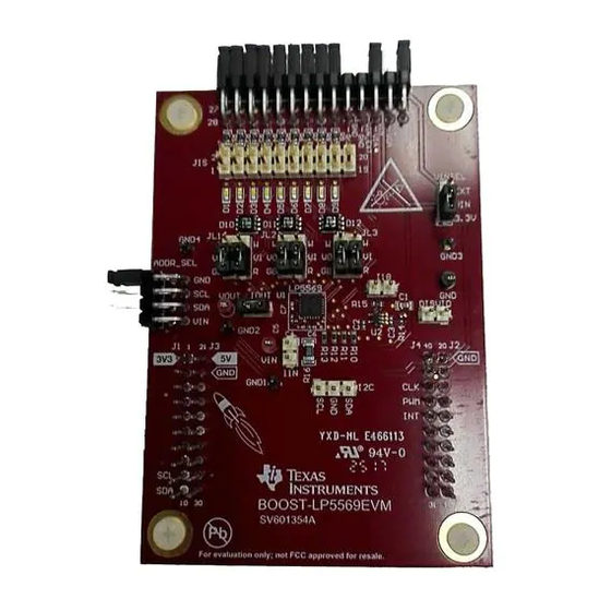
Using the BOOST-LP5569EVM Evaluation Module
The Texas Instruments LP5569 evaluation module (EVM) helps designers evaluate the operation and
performance of the LP5569 nine-LED driver. The LP5569 device is an RGB LED driver that can
individually control up to 9 LEDs. The driver has 12-bit PWM and 8-bit current control of each low-side
LED current sink. The current sinks can be individually controlled through the I
The EVM contains one LP5569 device (see
..........................................................................................................................
1
1.1
2
1.2
I
1.3
1.4
1.5
1.6
1.7
1.8
2
2.1
2.2
2.3
2.4
2.5
2.6
2.7
2.8
2.9
2.10
2.11
2.12
2.13
2.14
2.15
3
3.1
3.2
3.3
3.4
3.5
3.6
3.7
4
Table 1. Device and Package Configurations
REFERENCE ID
U1
..............................................................................................
..................................................................................
................................................................................................
...............................................................................................
............................................................................................
................................................................................................................
.........................................................................................
.......................................................................................
............................................................................................
......................................................................................
.........................................................................................................
..........................................................................................................
...................................................................................................
......................................................................................................
.......................................................................................................
.....................................................................................
.................................................................................
..........................................................................................
.............................................................................................................
.....................................................................................................
........................................................................................
...............................................................................................
.......................................................................................................
...........................................................................................................
...............................................................................................................
............................................................................................
..........................................................................................
................................................................................................................
Copyright © 2017, Texas Instruments Incorporated
SNVU564A - July 2017 - Revised August 2017
Table
1).
DEVICE
PACKAGE
LP5569
WQFN (24)
Contents
..............................................................................
..................................................................
..............................................................................
User's Guide
2
C interface.
........................................
.................................
3
3
3
3
4
5
6
6
8
9
9
14
16
16
18
18
18
19
19
21
24
25
25
27
27
29
29
30
30
31
31
32
34
38
1
Advertisement
Table of Contents

Related Manuals for Texas Instruments BOOST-LP5569EVM


Summary of Contents for Texas Instruments BOOST-LP5569EVM
-
Page 1: Table Of Contents
SNVU564A – July 2017 – Revised August 2017 Using the BOOST-LP5569EVM Evaluation Module The Texas Instruments LP5569 evaluation module (EVM) helps designers evaluate the operation and performance of the LP5569 nine-LED driver. The LP5569 device is an RGB LED driver that can individually control up to 9 LEDs. -
Page 2: Snvu564A – July 2017 – Revised August
Schematic ..................... Bill of Materials (BOM) Trademarks LaunchPad is a trademark of Texas Instruments. Microsoft, Windows are registered trademarks of Microsoft Corporation. All other trademarks are the property of their respective owners. Using the BOOST-LP5569EVM Evaluation Module SNVU564A – July 2017 – Revised August 2017 Submit Documentation Feedback Copyright ©... -
Page 3: Setup
The connectors JL1, JL2, and JL3 are used to select the LED type and supply rail. Figure 2. JL1, JL2, JL3 Configuration SNVU564A – July 2017 – Revised August 2017 Using the BOOST-LP5569EVM Evaluation Module Submit Documentation Feedback Copyright © 2017, Texas Instruments Incorporated... -
Page 4: Rgb Led Operation
The recommended settings, using shunts, are as follows: • ADDR_SEL: Shunt installed between pins 1 and 2 only. • IOUT: Shunt installed. Using the BOOST-LP5569EVM Evaluation Module SNVU564A – July 2017 – Revised August 2017 Submit Documentation Feedback Copyright © 2017, Texas Instruments Incorporated... -
Page 5: White Led Operation
19 and 20, 21 and 22, 23 and 24, 25 and 26, 27 and 28. In this configuration, the white LEDs are connected to the charge pump output. SNVU564A – July 2017 – Revised August 2017 Using the BOOST-LP5569EVM Evaluation Module Submit Documentation Feedback Copyright © 2017, Texas Instruments Incorporated... -
Page 6: External Led Operation
EVM and MSP-EXP432P401R LaunchPad Development Kit Setup The MSP-EXP432P401R LaunchPad jumpers should be set as shown in Figure Using the BOOST-LP5569EVM Evaluation Module SNVU564A – July 2017 – Revised August 2017 Submit Documentation Feedback Copyright © 2017, Texas Instruments Incorporated... - Page 7 Figure 6. MSP432 Jumper Settings Connect the MSP432 LaunchPad development kit and EVM (BOOSTXL-LP5569) as shown in Figure SNVU564A – July 2017 – Revised August 2017 Using the BOOST-LP5569EVM Evaluation Module Submit Documentation Feedback Copyright © 2017, Texas Instruments Incorporated...
-
Page 8: Minimum Procedure For Turning On The Leds
6. If the LaunchPad development kit is a new one or was used another purpose, the EVM software asks to update the firmware. Update the firmware through the top menu, File → Update Firmware. The EVM software restarts after updating the firmware. Using the BOOST-LP5569EVM Evaluation Module SNVU564A – July 2017 – Revised August 2017 Submit Documentation Feedback... -
Page 9: Evm Software
Run button even though the Windows security warning message appears. Click the Next button. SNVU564A – July 2017 – Revised August 2017 Using the BOOST-LP5569EVM Evaluation Module Submit Documentation Feedback Copyright © 2017, Texas Instruments Incorporated... - Page 10 Figure 9. Setting Up the LP5569 EVM Check to accept the agreement and click the Next button to proceed with the installation. Using the BOOST-LP5569EVM Evaluation Module SNVU564A – July 2017 – Revised August 2017 Submit Documentation Feedback Copyright © 2017, Texas Instruments Incorporated...
- Page 11 Figure 10. License Agreement Click Next button. By default, the program is installed in the C:\Program Files (x86)\Texas Instruments\LP5569 folder and Texas Instruments\LP5569EVM in the start menu. SNVU564A – July 2017 – Revised August 2017 Using the BOOST-LP5569EVM Evaluation Module Submit Documentation Feedback Copyright ©...
- Page 12 EVM Software www.ti.com Figure 11. Installation Directory Dialog Click the Next button to proceed with the installation. Using the BOOST-LP5569EVM Evaluation Module SNVU564A – July 2017 – Revised August 2017 Submit Documentation Feedback Copyright © 2017, Texas Instruments Incorporated...
- Page 13 Check to create a desktop icon for the program and check to launch the EVM software after installation. SNVU564A – July 2017 – Revised August 2017 Using the BOOST-LP5569EVM Evaluation Module Submit Documentation Feedback Copyright © 2017, Texas Instruments Incorporated...
-
Page 14: Xds110 Driver Installation
Connect the PC and MSP-EXP432P401R LaunchPad development kit using a USB cable and open the Device Manager of Windows (Control Panel→Device Manager). Verify that XDS110 Class Application/User UART and XDS110 Class Auxiliary Data Port appear. Using the BOOST-LP5569EVM Evaluation Module SNVU564A – July 2017 – Revised August 2017 Submit Documentation Feedback... - Page 15 EVM software is already installed. The default EVM software installation folder is C:\Program Files (x86)\Texas Instruments\LP5569 EVM. SNVU564A – July 2017 – Revised August 2017 Using the BOOST-LP5569EVM Evaluation Module Submit Documentation Feedback Copyright © 2017, Texas Instruments Incorporated...
-
Page 16: Evm Software Launch
Figure 16. Driver Installation EVM Software Launch Run C:\Program Files (x86)\Texas Instruments\ LP5569 EVM\LP5569_EVM.exe if the default installation folder was not modified in the EVM software installation step or click the desktop icon, LP5569_EVM. Figure 17. Desktop Icon Update Firmware for MSP-EXP432P401R LaunchPad Development Kit The MSP-EXP432P401R LaunchPad development kit can be used for many purposes. - Page 17 A firmware-download-status popup is displayed after finishing the firmware update. Figure 20. Firmware Download Status The EVM software is restarted after updating the firmware. SNVU564A – July 2017 – Revised August 2017 Using the BOOST-LP5569EVM Evaluation Module Submit Documentation Feedback Copyright © 2017, Texas Instruments Incorporated...
-
Page 18: Msp432 Firmware Running
MSP432 LaunchPad development kit, the light blue sign Hardware Connected is displayed. Figure 23. Status Bar (Hardware Connected) Using the BOOST-LP5569EVM Evaluation Module SNVU564A – July 2017 – Revised August 2017 Submit Documentation Feedback... -
Page 19: Information View
The register view is shown when the Register icon is clicked, and it provides the register values, field values, and descriptions. SNVU564A – July 2017 – Revised August 2017 Using the BOOST-LP5569EVM Evaluation Module Submit Documentation Feedback Copyright © 2017, Texas Instruments Incorporated... - Page 20 RegisterName group. Any RegisterName that is expanded can be collapsed by clicking on the RegisterName a second time. Figure 26. Register View (Expanded) Using the BOOST-LP5569EVM Evaluation Module SNVU564A – July 2017 – Revised August 2017 Submit Documentation Feedback...
-
Page 21: Control Menu
External Clock Control – External clock pin control. Red color means that a 32.7-kHz external clock is operating. SNVU564A – July 2017 – Revised August 2017 Using the BOOST-LP5569EVM Evaluation Module Submit Documentation Feedback Copyright © 2017, Texas Instruments Incorporated... - Page 22 Regarding pwm(x) and current(x), an Update button click is required to write data through I after changing the value by using the slide bar or text box. Figure 29. LED ON-OFF Control Using the BOOST-LP5569EVM Evaluation Module SNVU564A – July 2017 – Revised August 2017 Submit Documentation Feedback...
- Page 23 The LED_FAULT1, LED_FAULT2, and GENERAL_FAULT registers can be read by clicking the read button or selecting the poll check box. The polling time to read the fault registers is 1s. SNVU564A – July 2017 – Revised August 2017 Using the BOOST-LP5569EVM Evaluation Module Submit Documentation Feedback Copyright © 2017, Texas Instruments Incorporated...
-
Page 24: Control View - Program Tab
Run Program—This mode executes the instructions stored in the program memory. Execution register (ENG1_EXEC, and so forth) bits define how the program is executed (hold, step, free run, or execute Using the BOOST-LP5569EVM Evaluation Module SNVU564A – July 2017 – Revised August 2017 Submit Documentation Feedback Copyright ©... -
Page 25: Control View - Code Memory Tab
The Source Edit tab on the control view provides the interfaces to create or edit a source file and compile. SNVU564A – July 2017 – Revised August 2017 Using the BOOST-LP5569EVM Evaluation Module Submit Documentation Feedback Copyright © 2017, Texas Instruments Incorporated... - Page 26 Figure 36. File List After Compilation 2.13.5 Input Instruction A source file can be edited using the interfaces on the Input Instruction group. Using the BOOST-LP5569EVM Evaluation Module SNVU564A – July 2017 – Revised August 2017 Submit Documentation Feedback Copyright © 2017, Texas Instruments Incorporated...
-
Page 27: Control View - Log Tab
Field read FIELD_NAME must be same FIELD_NAME() exp_en0(); read exp_en0 bit as the register map on the GUI SNVU564A – July 2017 – Revised August 2017 Using the BOOST-LP5569EVM Evaluation Module Submit Documentation Feedback Copyright © 2017, Texas Instruments Incorporated... - Page 28 1 read_all(); read all regsiters wait(1000); en_pin(low); en pin set to low} Figure 38. Console Window Figure 39. Macro File Using the BOOST-LP5569EVM Evaluation Module SNVU564A – July 2017 – Revised August 2017 Submit Documentation Feedback Copyright © 2017, Texas Instruments Incorporated...
-
Page 29: Lp5569 Programming
PSPad usage.) Then the program is compiled into hex and binary files. Finally, the hex file is loaded into the LP5569 memory and tested. Figure 40. Programming Flow Chart SNVU564A – July 2017 – Revised August 2017 Using the BOOST-LP5569EVM Evaluation Module Submit Documentation Feedback Copyright © 2017, Texas Instruments Incorporated... -
Page 30: Reserved Keywords
• • .segment Commenting Commenting starts with a semicolon (;). The assembler ignores all characters after a semicolon. Using the BOOST-LP5569EVM Evaluation Module SNVU564A – July 2017 – Revised August 2017 Submit Documentation Feedback Copyright © 2017, Texas Instruments Incorporated... -
Page 31: Directives
Time is a positive Wait 0.25 seconds. constant (0 to 0.484). Note: time is rounded by assembler if needed. SNVU564A – July 2017 – Revised August 2017 Using the BOOST-LP5569EVM Evaluation Module Submit Documentation Feedback Copyright © 2017, Texas Instruments Incorporated... -
Page 32: Instruction Set Details
An SRAM address containing mapping data is restricted to lower half of memory. Using the BOOST-LP5569EVM Evaluation Module SNVU564A – July 2017 – Revised August 2017 Submit Documentation Feedback Copyright © 2017, Texas Instruments Incorporated... - Page 33 (ra, rb, location. rc, rd); address is a label which specifies the offset. SNVU564A – July 2017 – Revised August 2017 Using the BOOST-LP5569EVM Evaluation Module Submit Documentation Feedback Copyright © 2017, Texas Instruments Incorporated...
-
Page 34: Programming Examples
2, 255 ramp 2, –255 ramp 2, -255 branch 0, loop1 .segment program2 trigger w{1} map_addr ENG2 Using the BOOST-LP5569EVM Evaluation Module SNVU564A – July 2017 – Revised August 2017 Submit Documentation Feedback Copyright © 2017, Texas Instruments Incorporated... - Page 35 ENG3 loop3: ramp 2, –255 ramp 2, –255 ramp 2, 255 branch 0, loop3 SNVU564A – July 2017 – Revised August 2017 Using the BOOST-LP5569EVM Evaluation Module Submit Documentation Feedback Copyright © 2017, Texas Instruments Incorporated...
- Page 36 0000 0001 0001 0001b 01 008C ENG2: 0000 0000 1000 1100b 02 0062 ENG3: 0000 0000 0110 0010b Using the BOOST-LP5569EVM Evaluation Module SNVU564A – July 2017 – Revised August 2017 Submit Documentation Feedback Copyright © 2017, Texas Instruments Incorporated...
- Page 37 = 08 loop2 = 0F loop3 = 16 ======================== ======== Segments: program1 = 04 program2 = 0D SNVU564A – July 2017 – Revised August 2017 Using the BOOST-LP5569EVM Evaluation Module Submit Documentation Feedback Copyright © 2017, Texas Instruments Incorporated...
-
Page 38: Board Layout
Table 9. Example .lst File (continued) program3 = 14 ======================== ======== Free memory: 228 Errors: 0 Board Layout Figure 42. Top Assembly Layer Using the BOOST-LP5569EVM Evaluation Module SNVU564A – July 2017 – Revised August 2017 Submit Documentation Feedback Copyright © 2017, Texas Instruments Incorporated... - Page 39 Board Layout www.ti.com Figure 43. Top Layer Routing Figure 44. Middle Layer 1 Routing SNVU564A – July 2017 – Revised August 2017 Using the BOOST-LP5569EVM Evaluation Module Submit Documentation Feedback Copyright © 2017, Texas Instruments Incorporated...
- Page 40 Board Layout www.ti.com Figure 45. Middle Layer 2 Routing Figure 46. Bottom Layer Routing (Mirrored) Using the BOOST-LP5569EVM Evaluation Module SNVU564A – July 2017 – Revised August 2017 Submit Documentation Feedback Copyright © 2017, Texas Instruments Incorporated...
- Page 41 Schematic www.ti.com Schematic Figure 47. LP5569EVM Schematic SNVU564A – July 2017 – Revised August 2017 Using the BOOST-LP5569EVM Evaluation Module Submit Documentation Feedback Copyright © 2017, Texas Instruments Incorporated...
- Page 42 Texas Instruments driver, RTW0024B (WQFN-24) Micropower, 150-mA low-dropout CMOS MAA05A LP5951MG-1.8/NOPB Texas Instruments voltage regulator, 5-pin SC-70, Pb-free Using the BOOST-LP5569EVM Evaluation Module SNVU564A – July 2017 – Revised August 2017 Submit Documentation Feedback Copyright © 2017, Texas Instruments Incorporated...
- Page 43 STANDARD TERMS FOR EVALUATION MODULES Delivery: TI delivers TI evaluation boards, kits, or modules, including any accompanying demonstration software, components, and/or documentation which may be provided together or separately (collectively, an “EVM” or “EVMs”) to the User (“User”) in accordance with the terms set forth herein.
- Page 44 FCC Interference Statement for Class B EVM devices NOTE: This equipment has been tested and found to comply with the limits for a Class B digital device, pursuant to part 15 of the FCC Rules. These limits are designed to provide reasonable protection against harmful interference in a residential installation.
- Page 45 【無線電波を送信する製品の開発キットをお使いになる際の注意事項】 開発キットの中には技術基準適合証明を受けて いないものがあります。 技術適合証明を受けていないもののご使用に際しては、電波法遵守のため、以下のいずれかの 措置を取っていただく必要がありますのでご注意ください。 1. 電波法施行規則第6条第1項第1号に基づく平成18年3月28日総務省告示第173号で定められた電波暗室等の試験設備でご使用 いただく。 2. 実験局の免許を取得後ご使用いただく。 3. 技術基準適合証明を取得後ご使用いただく。 なお、本製品は、上記の「ご使用にあたっての注意」を譲渡先、移転先に通知しない限り、譲渡、移転できないものとします。 上記を遵守頂けない場合は、電波法の罰則が適用される可能性があることをご留意ください。 日本テキサス・イ ンスツルメンツ株式会社 東京都新宿区西新宿6丁目24番1号 西新宿三井ビル 3.3.3 Notice for EVMs for Power Line Communication: Please see http://www.tij.co.jp/lsds/ti_ja/general/eStore/notice_02.page 電力線搬送波通信についての開発キットをお使いになる際の注意事項については、次のところをご覧ください。http:/ /www.tij.co.jp/lsds/ti_ja/general/eStore/notice_02.page 3.4 European Union 3.4.1 For EVMs subject to EU Directive 2014/30/EU (Electromagnetic Compatibility Directive): This is a class A product intended for use in environments other than domestic environments that are connected to a low-voltage power-supply network that supplies buildings used for domestic purposes.
- Page 46 Notwithstanding the foregoing, any judgment may be enforced in any United States or foreign court, and TI may seek injunctive relief in any United States or foreign court. Mailing Address: Texas Instruments, Post Office Box 655303, Dallas, Texas 75265 Copyright © 2018, Texas Instruments Incorporated...
- Page 47 IMPORTANT NOTICE FOR TI DESIGN INFORMATION AND RESOURCES Texas Instruments Incorporated (‘TI”) technical, application or other design advice, services or information, including, but not limited to, reference designs and materials relating to evaluation modules, (collectively, “TI Resources”) are intended to assist designers who are developing applications that incorporate TI products;...