Table of Contents
Advertisement
Service Literature
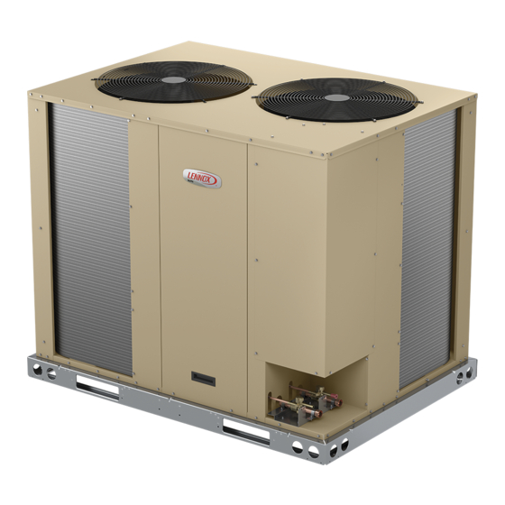
The ELS units are designed for light commercial applica-
tions, with a remotely located blower-coil unit or a furnace
with an add-on evaporator coil. Capacities for the series
are 6, 7-1/2, 10, 12.5, 15 and 20 tons (21, 26, 35, 44,
53, and 70 kW).ELS072, ELS090 and ELS120S4S mod-
els have one dual-speed scroll compressor. ELS120S4D,
ELS150S4D, ELS180S4D and ELS240S4D models have
two single-speed scroll compressors. ELS units match
with the ELA blower-coil units. All ELS units are three
phase and use HFC-410A refrigerant.
This
manual
covers
ELS120S4S, ELS120S4D, ELS150S4D, ELS180S4D and
ELS240S4D units. It is divided into sections which discuss
the major components, refrigerant system, charging pro-
cedure, maintenance and operation sequence.
Information in this manual is intended for qualified service
technicians only. All specifications are subject to change.
Procedures in this manual are presented as a recommen-
dation only and do not supersede or replace local or state
codes.
WARNING
Improper installation, adjustment, alteration, service
or maintenance can cause property damage, personal
injury or loss of life. Installation and service must be
performed by a licensed professional HVAC installer or
equivalent, service agency, or the gas supplier.
IMPORTANT
The Clean Air Act of 1990 bans the intentional venting of
refrigerant (CFCs, HCFCs and HFCs) as of July 1, 1992.
Approved methods of recovery, recycling or reclaiming
must be followed. Fines and/or incarceration may be
levied for noncompliance.
WARNING
Electric shock hazard! - Disconnect all power
supplies before servicing.
Replace all parts and panels before
operating.
Failure to do so can result in death or
electrical shock.
CAUTION
As with any mechanical equipment, contact with sharp
sheet metal edges can result in personal injury. Take
care while handling this equipment and wear gloves and
protective clothing.
UNIT INFORMATION
ELS SERIES UNITS
ELS072S4S,
ELS090S4S,
Corp. 1811-L3
May 15, 2018
Table of Contents
Unit Plumbing Parts Arrangement .................................5
Model Number Identification ........................................10
Unit Control Box Components Arrangement ................ 11
I-UNIT COMPONENTS ................................................12
A-CONTROL BOX COMPONENTS ............................12
B-COOLING COMPONENTS .......................................12
II- REFRIGERANT SYSTEM .......................................13
A-Plumbing ..................................................................13
B-Service Valves .........................................................14
III-START-UP ................................................................15
IV-CHARGING ..............................................................16
A-Leak Testing ..............................................................16
B-Evacuating the System .............................................17
C-Charging ...................................................................18
V-MAINTENANCE ........................................................22
VI-Wiring Diagram and Sequence of Operation ...........23
Page 1
ELS
6 - 20 TON
Advertisement
Table of Contents

Related Manuals for Lennox ELS SERIES


Summary of Contents for Lennox ELS SERIES
-
Page 1: Table Of Contents
6 - 20 TON May 15, 2018 Service Literature ELS SERIES UNITS The ELS units are designed for light commercial applica- tions, with a remotely located blower-coil unit or a furnace with an add-on evaporator coil. Capacities for the series are 6, 7-1/2, 10, 12.5, 15 and 20 tons (21, 26, 35, 44,... - Page 2 NOTE - Extremes of operating range are plus and minus 10% of line voltage. Field provided charge with 25 ft. line set. Refer to the Lennox Refrigerant Piping Manual to determine refrigerant charge required with longer length refrigerant lines. HACR type circuit breaker or fuse.
- Page 3 NOTE - Extremes of operating range are plus and minus 10% of line voltage. Field provided charge with 25 ft. line set. Refer to the Lennox Refrigerant Piping Manual to determine refrigerant charge required with longer length refrigerant lines. HACR type circuit breaker or fuse.
- Page 4 OPTIONS / ACCESSORIES Item Catalog CABINET Combined Coil/Hail Guards T2GARD51L-1 13T29 T2GARD51M11 13T30 T2GARD51M21 13T32 T2GARD51N-1 13T37 Corrosion Protection Factory CONTROLS BACnet Module A0CTRL31LS1 17A08 ® K0SNSR01FF1 97W23 BACnet Sensor with Display ® BACnet Sensor without Display K0SNSR00FF1 97W24 ® Network Thermostat Control (NTC) C0CTRL07AE1L 17M10 A0CTRL32LS1 16H99...
-
Page 5: Unit Plumbing Parts Arrangement
Unit Plumbing Parts Arrangement ELS072S4S ELS090S4S Page 5... - Page 6 ELS120S4S ELS120S4D – STAGE 2 Page 6...
- Page 7 ELS120S4D – STAGE 1 ELS150S4D – STAGE 2 Page 7...
- Page 8 ELS150S4D – STAGE 1 ELS180S4D – STAGE 2 Page 8...
- Page 9 ELS180S4D – STAGE 1 ELS240S4D – STAGE 2 Page 9...
-
Page 10: Model Number Identification
ELS240S4D – STAGE 1 Model Number Identification E L S 120 S Voltage Brand/Family Elite™ Product Line Y = 208/230V 3 phase 60hz G = 460V 3 phase 60hz J = 575V 3 phase 60hz M = 380/420V 3 phase 50hz Minor Design Sequence 1 = 1st Revision S = Split System Air Conditioner... -
Page 11: Unit Control Box Components Arrangement
Unit Control Box Components Arrangement ICM CONTROLLER (FIELD INSTALLED) ICM CONTROLLER (FIELD INSTALLED) TRANSFORMER TRANSFORMER ELS120S ELS072/090S ICM CONTROLLER (FIELD INSTALLED) ICM CONTROLLER (FIELD INSTALLED) TRANSFORMER TRANSFORMER CONTACTOR CONTACTOR ELS180D / ELS240D ELS120D/ELS150D Page 11... -
Page 12: I-Unit Components
I-UNIT COMPONENTS 4 - Compressor Contactor K1 (all units) K2 (120S4D, 150, 180, 240) The ELS parts arrangements are shown on pages 5 - 10 All compressor contactors are three-pole double-break and control boxes on page 11. contactors with auxiliary switch with a 24V coil. In WARNING ELS072, 090 and 120S4S, K1 energizes compressor B1. -
Page 13: Ii- Refrigerant System
(120S4D, 150, 180, 240) at the corner of the unit below the control box. Piping can All ELS series units use a belly-band type crankcase heat- be routed directly from the service valves or field supplied er. Heater HR1 is wrapped around compressor B1 and elbows can be added to divert the piping as required Refer heater HR2 is wrapped around compressor B2. -
Page 14: B-Service Valves
1 - Remove service port cap with an appropriately fittings). Size refrigerant lines greater than 50 linear feet sized wrench. (15m or greater) according to the Lennox Refrigerant Pip- 2 - Connect gauge to the service port. ing Design and Fabrication Guidelines (Corp. 9351-L9) or latest version. -
Page 15: Iii-Start-Up
III-START-UP Liquid And Suction Line Service Valve The following is a general procedure and does not apply (Valve Open) stem cap to all thermostat control systems. Refer to sequence of insert hex operation in this manual for more information. wrench here IMPORTANT service port... -
Page 16: Iv-Charging
4 - Close the valve on the HFC-410A cylinder and the IV-CHARGING valve on the high pressure side of the manifold A-Leak Testing gauge set. WARNING 5 - Disconnect the HFC-410A cylinder. 6 - Connect a cylinder of dry nitrogen with a pressure Refrigerant can be harmful if it is inhaled. -
Page 17: B-Evacuating The System
MANIFOLD Connect an HFC-410A manifold gauge set high pressure hose to the GAUGE SET suction valve service port. With both manifold valves closed, connect the cylinder of HFC-410A refrigerant to the center port of the manifold gauge set. After the line set has been connected to both the indoor and outdoor units, check the line set connections and indoor unit for leaks. -
Page 18: C-Charging
If line set is less than 25 feet, subtract this 4 - When the absolute pressure reaches 23,000 amount from each circuit. Refer to Lennox Refrigerant microns (29 inches of mercury), close the manifold Piping Design and Fabrication Guidelines for more infor- mation. - Page 19 4 - Compare the normal operating pressures to 2 - Approach temperature should as indicated in table the pressures obtained from the gauges. Minor 4 for each stage. An approach temperature greater variations in these pressures may be expected due than this value indicates an undercharge.
- Page 20 TABLE 6 HFC-410A Normal Operating Pressures (Liquid ±10 and Suction ±5 psig) (Dual-Stage Units)** -150S4D -150S4D -120S4D -120S4D STAGE 1 STAGE 2 STAGE 1 STAGE 2 Temp* Liquid Suction Liquid Suction Liquid Suction Liquid Suction 65 F (18 C) 75 F (24 C) 85 F (29 C) 95 F (35 C) 105 F (41 C)
- Page 21 TABLE 8. Normal Operating Temperatures – Residential Matchups ELS120S4D + (2) CBA27UHE-060 or ELS120S4D + (2) CH33-62D ELS120S4D + (2) CH23-068 (2) CBA38MV-060 Normal Operating Pressures Normal Operating Pressures Normal Operating Pressures Liquid at Liquid at Liquid at (ºF) Suction (ºF) Suction (ºF)
-
Page 22: V-Maintenance
V-MAINTENANCE INDOOR COIL 1 - Clean coil if necessary. Installation and service must be performed by a licensed professional installer (or equivalent) or a service agen- 2 - Check connecting lines, joints and coil for evidence cy. At the beginning of each cooling season, the system of oil leaks. -
Page 23: Vi-Wiring Diagram And Sequence Of Operation
VI-Wiring Diagram and Sequence of Operation A-ELS072-120S TB14 COOL 2 COOL 1 CIRCUIT BREAKER-TRANS T1 K10,-1 K67-1 SWITCH-LOSS OF CHARGE,COMP 1 TRANSFORMER-CONTROL TB14 TERMINAL STRIP-CLASS II VOLTAGE LINE VOLTAGE FIELD INSTALLED DENOTES OPTIONAL COMPONENTS WIRING DIAGRAM 09/17 DUAL SPEED COMPRESSOR ELS-072,090,120-G,J,M,Y SECTION A2 REV. - Page 24 B-ELS120S4D, 150 TB14 COOL 2 COOL 1 TB14 LINE VOLTAGE FIELD INSTALLED DENOTES OPTIONAL COMPONENTS CIRCUIT BREAKER-TRANS T1 SWITCH-LOSS OF CHARGE,COMP 1 SWITCH-LOSS OF CHARGE,COMP 2 TRANSFORMER-CONTROL TERMINAL STRIP-CLASS II VOLTAGE TB14 K10,-1 WIRING DIAGRAM K66,-1,2 08/17 K67,-1,2 ELS-120,150-G,J,M,Y SECTION A 3 REV.
- Page 25 C-ELS180, 240 TB14 COOL 2 COOL 1 TB14 SWITCH-LOSS OF CHARGE,COMP 1 SWITCH-LOSS OF CHARGE,COMP 2 TRANSFORMER-CONTROL TB14 TERMINAL STRIP-CLASS II VOLTAGE DENOTES OPTIONAL COMPONENTS LINE VOLTAGE FIELD INSTALLED K10,-1 K66,-1,2 K67,-1,2 K149,-1 CIRCUIT BREAKER-TRANS T1 08/17 WIRING DIAGRAM SINGLE SPEED COMPRESSOR ELS-180,240-G,J,M,Y SECTION A 4 REV.