Table of Contents
Advertisement
Quick Links
Advertisement
Table of Contents

Related Manuals for Asus WS C246M PRO


Summary of Contents for Asus WS C246M PRO
- Page 1 WS C246M...
- Page 2 Product warranty or service will not be extended if: (1) the product is repaired, modified or altered, unless such repair, modification of alteration is authorized in writing by ASUS; or (2) the serial number of the product is defaced or missing.
-
Page 3: Table Of Contents
Contents Safety information ...................... vi About this guide ......................vii WS C246M PRO specifications summary ..............ix Package contents ....................... xi Installation tools and components ................xii Chapter 1: Product Introduction Motherboard overview ................1-1 1.1.1 Before you proceed ..............1-1 1.1.2... - Page 4 Contents Chapter 3: BIOS Setup Managing and updating your BIOS ............3-1 3.1.1 ASUS CrashFree BIOS 3 utility........... 3-1 3.1.2 ASUS EzFlash Utility..............3-2 3.1.3 BUPDATER utility ............... 3-3 BIOS setup program .................. 3-5 3.2.1 BIOS menu screen ..............3-6 3.2.2...
- Page 5 Creating a RAID set ..............4-9 4.3.2 Changing a Volume Type............4-11 4.3.3 Deleting a volume ..............4-12 4.3.4 Preferences ................4-13 Appendix WS C246M PRO block diagram ................A-1 Q-Code table ......................A-2 Notices ........................A-5 ASUS contact information ..................A-9...
-
Page 6: Safety Information
Safety information Electrical safety • To prevent electrical shock hazard, disconnect the power cable from the electrical outlet before relocating the system. • When adding or removing devices to or from the system, ensure that the power cables for the devices are unplugged before the signal cables are connected. If possible, disconnect all power cables from the existing system before you add a device. -
Page 7: About This Guide
Refer to the following sources for additional information and for product and software updates. ASUS website The ASUS website (www.asus.com) provides updated information on ASUS hardware and software products. Optional documentation Your product package may include optional documentation, such as warranty flyers, that may have been added by your dealer. - Page 8 Conventions used in this guide To ensure that you perform certain tasks properly, take note of the following symbols used throughout this manual. DANGER/WARNING: Information to prevent injury to yourself when trying to complete a task. CAUTION: Information to prevent damage to the components when trying to complete a task.
-
Page 9: Ws C246M Pro Specifications Summary
4 x DIMM, Max 64GB, DDR4 2666 / 2400 / 2133 MHz, ECC/ non-ECC UDIMM* Memory Dual channel architecture * Refer to www.asus.com for the Memory QVL(Qualified Vendors List) PCIEX1_1: PCI-E x1 slot, x1 Gen3 Link, from PCH PCIEX16_1: PCI-E x16 slot, x16 Gen3 Link Expansion slots... - Page 10 - 18-pin AUX panel connector 32 MB Flash ROM, EFI AMI BIOS, PnP, DMI3.0, WfM2.0, SM BIOS 3.0, BIOS Feature ACPI 5.0a, ASUS EZ Flash Utility, ASUS CrashFree BIOS 3 WfM 2.0, DMI 3.0, WOL by PME, WOR by PME, PXE Manageability...
-
Page 11: Package Contents
Package contents Check your motherboard package for the following items. Motherboard 1 x WS C246M PRO motherboard 6 x Serial ATA 6Gb/s cables Cables 1 x USB 2.0 bracket cable 2 x M.2 screws kits Accessories 1 x COM port brackets... -
Page 12: Installation Tools And Components
Installation tools and components Intel LGA1151 compatible CPU Fan Intel LGA1151 CPU ® ® Phillips (cross) screwdriver SATA hard disk drive PC chassis Power supply unit 1 bag of screws DIMM SATA optical disc drive (optional) Graphics card The tools and components in the table above are not included in the motherboard package. -
Page 13: Chapter 1: Product Introduction
Chapter 1: Product Introduction Product Introduction Motherboard overview 1.1.1 Before you proceed Take note of the following precautions before you install motherboard components or change any motherboard settings. • Unplug the power cord from the wall socket before touching any component. • Before handling components, use a grounded wrist strap or touch a safely grounded object or a metal object, such as the power supply case, to avoid damaging them due to static electricity. • Hold components by the edges to avoid touching the ICs on them. • Whenever you uninstall any component, place it on a grounded antistatic pad or in the bag that came with the component. • Before you install or remove any component, ensure that the ATX power supply is switched off or the power cord is detached from the power supply. Failure to do so may cause severe damage to the motherboard, peripherals, or components. ASUS WS C246M PRO... -
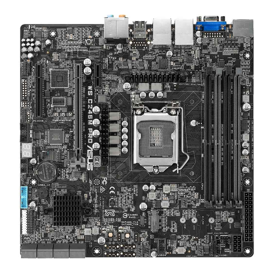
Page 14: Motherboard Layout
1.1.2 Motherboard layout Refer to 1.1.9 Internal connectors and 2.3.1 Rear I/O connection for more information about rear panel connectors and internal connectors. Chapter 1: Product Introduction... - Page 15 16. USB 3.1 Gen 1 connector (20-1 pin USB3_12) 1-19 17. Storage device activity LED connector (4-pin HDLED1) 1-20 18. Chassis Intrusion (2-pin INTRUSION1) 1-26 19. Q-Code LED 1-16 20. Serial port connector (10-1 pin COM1) 1-19 21. TPM connector (14-1 pin TPM1) 1-18 22. Digital audio connector (4-1 pin SPDIF_OUT1) 1-21 23. Front panel audio connector (10-1 pin AAFP) 1-18 24. Clear RTC RAM (3-pin CLRTC1) 25. Thermal sensor cable connector (3-pin TR1) 1-23 26. Power-on button 27. LGA1151 CPU socket 28. LAN controller setting (3-pin LAN_SW2) 1-10 ASUS WS C246M PRO...
-
Page 16: Central Processing Unit (Cpu)
1.1.3 Central Processing Unit (CPU) The motherboard comes with a surface mount LGA1151 socket designed for the Intel ® Xeon Processor E Family (Coffee Lake) / Intel Pentium™ processors / Intel Celeron™ ® ® ® processors. Ensure that you install the correct CPU designed for LGA1151 socket only. DO NOT install a CPU designed for other sockets on the LGA1151 socket. • Ensure that all power cables are unplugged before installing the CPU. • Upon purchase of the motherboard, ensure that the PnP cap is on the socket and the socket contacts are not bent. Contact your retailer immediately if the PnP cap is missing, or if you see any damage to the PnP cap/socket contacts/motherboard components. ASUS will shoulder the cost of repair only if the damage is shipment/ transit-related. • Keep the cap after installing the motherboard. ASUS will process Return Merchandise Authorization (RMA) requests only if the motherboard comes with the cap on the LGA2066 socket. • The product warranty does not cover damage to the socket contacts resulting from incorrect CPU installation/removal, or misplacement/loss/incorrect removal of the PnP cap. Chapter 1: Product Introduction... -
Page 17: System Memory
1.1.4 System memory The motherboard comes with four DDR 4 (Double Data Rate 4) Dual Inline Memory Modules (DIMM) slots. A DDR4 module is notched differently from a DDR, DDR2 or DDR3 module. DO NOT install a DDR, DDR2 or DDR3 memory module to the DDR4 slot. Recommended memory configurations ASUS WS C246M PRO... - Page 18 Memory configurations You may install 2 GB, 4 GB, 8 GB and 16 GB unbuffered and ECC and non-ECC DDR4 DIMMs into the DIMM sockets. You may install varying memory sizes in Channel A and Channel B. The system maps the total size of the lower-sized channel for the dual-channel configuration. Any excess memory from the higher-sized channel is then mapped for single-channel operation. • The default memory operation frequency is dependent on its Serial Presence Detect (SPD), which is the standard way of accessing information from a memory module. Under the default state, some memory modules for overclocking may operate at a lower frequency than the vendor-marked value. • For system stability, use a more efficient memory cooling system to support a full memory load (8 DIMMs) or overclocking condition. • Always install the DIMMS with the same CAS Latency. For an optimum compatibility, we recommend that you install memory modules of the same version or data code (D/C) from the same vendor. Check with the vendor to get the correct memory modules. • Visit the ASUS website for the latest QVL. Chapter 1: Product Introduction...
-
Page 19: Expansion Slots
1.1.5 Expansion slots Unplug the power cord before adding or removing expansion cards. Failure to do so may cause you physical injury and damage motherboard components. Slot No. Slot Description PCIE x1_1 slot PCIE x16_1 slot PCIE x8_1 slot PCI Express 3.0 operating mode VGA / PCIe configuration Single VGA / PCIe card PCIe 3.0 x1_1 PCIe 3.0 x16_1 PCIe 3.0 x8_1 ASUS WS C246M PRO... -
Page 20: Onboard Buttons And Switches
1.1.6 Onboard buttons and switches Onboard buttons and switches allow you to fine-tune performance when working on a bare or open-case system. This is ideal for overclockers and gamers who continually change settings to enhance system performance. Power-on button The motherboard comes with a power-on button that allows you to power up or wake up the system. The LED near the button also lights up when the system is plugged to a power source indicating that you should shut down the system and unplug the power cable before removing or installing any motherboard component. Chapter 1: Product Introduction... -
Page 21: Jumpers
1.1.7 Jumpers Clear RTC RAM (3-pin CLRTC1) This jumper allows you to clear the Real Time Clock (RTC) RAM in CMOS. You can clear the CMOS memory of date, time, and system setup parameters by erasing the CMOS RTC RAM data. The onboard button cell battery powers the RAM data in CMOS, which include system setup information such as system passwords. To erase the RTC RAM: Turn OFF the computer and unplug the power cord. Move the jumper cap from pins 1-2 (default) to pins 2-3. Keep the cap on pins 2-3 for about 5-10 seconds, then move the cap back to pins 1-2. Plug the power cord and turn ON the computer. Hold down the <Del> key during the boot process and enter BIOS setup to reenter data. Except when clearing the RTC RAM, never short-circuit the CLRTC1 jumper. Shorting the CLRTC1 jumper will cause system boot failure! If the steps above do not help, remove the onboard battery and move the jumper again to clear the CMOS RTC RAM data. After the CMOS clearance, reinstall the battery. ASUS WS C246M PRO... - Page 22 LAN controller setting (3-pin LAN_SW2) This jumper allows you to enable or disable the onboard Intel I210-AT Gigabit (LAN_ ® SW2) controller. Set to pins 1–2 to activate the Gigabit LAN feature. ME firmware force recovery setting (3-pin ME_RCVR1) This jumper allows you to force Intel Management Engine (ME) boot from recovery ® mode when ME becomes corrupted. Chapter 1: Product Introduction 1-10...
- Page 23 PCH_MFG1 setting (3-pin PCH_MFG1) This jumper allows you to update the BIOS ME block. Smart Ride Through (SmaRT) setting (3-pin SMART_PSU1) This jumper allows you to enable or disable the Smart Ride Through (SmaRT) function. This feature is enabled by default. Set to pins 2-3 to disable it. When enabled, SmaRT allows uninterrupted operation of the system during an AC loss event. ASUS WS C246M PRO 1-11...
-
Page 24: Onboard Leds
1.1.8 Onboard LEDs Diagnosis LEDs The Diagnosis LEDs provide the status of these key components during POST (Power- On-Self Test): CPU, memory modules, VGA card, and hard disk drives. If an error is found, the critical component’s LED stays lit up until the problem is solved. The Diagnosis LEDs provide the most probable cause of an error code as a starting point for troubleshooting. The actual cause may vary from case to case. Standby Power LED (SBPWR1) The motherboard comes with a standby power LED. The green LED lights up to indicate that the system is ON, in sleep mode, or in soft-off mode. This is a reminder that you should shut down the system and unplug the power cable before removing or plugging in any motherboard component. The illustration below shows the location of the onboard LED. Chapter 1: Product Introduction 1-12... - Page 25 CPU Warning LED (ERRCPU1) The CPU warning LED lights up to indicate that a CPU error or failure has occurred. Message LED (MLED1) This onboard LED lights up to indicate that there is a temperature warning or a BMC event log is generated. ASUS WS C246M PRO 1-13...
- Page 26 BMC LED (BMCLED1) The BMC LED lights up to indicate that the on-board BMC is functional. ME LED (MELED1) The ME LED is an onboard LED that blinks when the ME is operating properly. Chapter 1: Product Introduction 1-14...
- Page 27 CATT ERR LED (CATTERR1) The CATT ERR LED indicates that the system has experienced a fatal or catastrophic error and cannot continue to operate. USB BIOS Flashback LED (FLBK_LED) The BIOS Flashback LED flashes when you press the BIOS Flashback button for BIOS update. ASUS WS C246M PRO 1-15...
- Page 28 Q-Code LED The Q-Code LED design provides you with a 2-digit error code that displays the system status. • The Q-Code LED provides the most probable cause of an error code as a starting point for troubleshooting. The actual cause may vary from case to case. • Please refer to the Q-Code table in the Appendix section for more details. Chapter 1: Product Introduction 1-16...
-
Page 29: Internal Connectors
1.1.9 Internal connectors Intel Serial ATA 6 Gb/s connectors (7-pin SATA6G_1-8) ® These connectors connect to Serial ATA 6 Gb/s hard disk drives via Serial ATA 6 Gb/s signal cables. If you installed Serial ATA hard disk drives, you can create a RAID 0, 1, 5, and 10 configuration with the Intel Rapid Storage Technology enterprise through the onboard ® Intel C246 chipset. ® These connectors are set to [AHCI Mode] by default. If you intend to create a Serial ATA RAID set using these connectors, set the SATA Mode item in the BIOS to [Intel RST Premium (RAID)]. ASUS WS C246M PRO 1-17... - Page 30 Front panel audio connector (10-1 pin AAFP) This connector is for a chassis-mounted front panel audio I/O module that supports HD Audio. Connect one end of the front panel audio I/O module cable to this connector. We recommend that you connect a high-definition front panel audio module to this connector to avail of the motherboard’s high-definition audio capability. TPM connector (14-1 pin TPM1) This connector supports a Trusted Platform Module (TPM) system, which securely store keys, digital certificates, passwords and data. A TPM system also helps enhance network security, protect digital identities, and ensures platform integrity. The TPM module is purchased separately. Chapter 1: Product Introduction 1-18...
- Page 31 Serial port connector (10-1 pin COM1) This connector is for a serial (COM) port. Connect the serial port module cable to this connector, then install the module to a slot opening at the back of the system chassis. USB 3.1 Gen 1 connector (20-1 pin USB3_12) This connector allows you to connect a USB 3.1 Gen 1 module for additional USB 3.1 Gen 1 front or rear panel ports. With an installed USB 3.1 Gen 1 module, you can enjoy all the benefits of USB 3.1 Gen 1 including faster data transfer speeds of up to 5 Gb/s, faster charging time for USB-chargeable devices, optimized power efficiency, and backward compatibility with USB 2.0. The USB 3.1 Gen 1 module is purchased separately. The plugged USB 3.1 Gen 1 device may run on xHCI or EHCI mode depending on the operating system’s setting. ASUS WS C246M PRO 1-19...
- Page 32 USB 2.0 connectors (10-1 pin USB34, USB78) The 10-1 pin connector allows you to connect a USB 2.0 module for additional USB 2.0 front or rear panel ports. These USB connectors comply with USB 2.0 specification that supports up to 480 Mbps connection speed. DO NOT connect a 1394 cable to the USB connectors. Doing so will damage the motherboard! Storage device activity LED connector (4-pin HDLED1) This LED connector is for the storage add-on card cable connected to the SATA or SAS add-on card. The read or write activities of any device connected to the SATA or SAS add-on card causes the front panel LED to light up. Chapter 1: Product Introduction 1-20...
- Page 33 Fan connectors (4-pin CPU_FAN1; 4-pin FRNT_FAN1-3; 4-pin REAR_FAN1) Connect the fan cables to the fan connectors on the motherboard, ensuring that the black wire of each cable matches the ground pin of the connector. • DO NOT forget to connect the fan cables to the fan connectors. Insufficient air flow inside the system may damage the motherboard components. These are not jumpers! Do not place jumper caps on the fan connectors! • Ensure that the CPU fan cable is securely installed to the CPU fan connector. Digital audio connector (4-1 pin SPDIF_OUT1) This connector is for an additional Sony/Philips Digital Interface (S/PDIF) port. Connect the S/PDIF Out module cable to this connector, then install the module to a slot opening at the back of the system chassis. The S/PDIF module is purchased separately. ASUS WS C246M PRO 1-21...
- Page 34 System panel connector (20-1 pin PANEL1) This connector supports several chassis-mounted functions. • System power LED (3-pin PLED) This 3-pin connector is for the system power LED. Connect the chassis power LED cable to this connector. The system power LED lights up when you turn on the system power, and blinks when the system is in sleep mode. • Message LED (2-pin MLED) This 2-pin connector is for the message LED cable that connects to the front message LED. The message LED is controlled by the BMC to indicate an abnormal event occurrence. • System warning speaker (4-pin SPEAKER) This 4-pin connector is for the chassis-mounted system warning speaker. The speaker allows you to hear system beeps and warnings. • Hard disk drive activity LED (2-pin +HDLED) This 2-pin connector is for the HDD Activity LED. Connect the HDD Activity LED cable to this connector. The LED lights up or flashes when data is read from or written to the HDD. • Power button/soft-off button (2-pin PWRSW) This connector is for the system power button. Pressing the power button turns the system on or puts the system in sleep or soft-off mode depending on the BIOS settings. Pressing the power switch for more than four seconds while the system is ON turns the system OFF. • Reset button (2-pin RESET) This 2-pin connector is for the chassis-mounted reset button for system reboot without turning off the system power. Chapter 1: Product Introduction 1-22...
- Page 35 Auxiliary panel connector (20-2 pin AUX_PANEL1) This connector is for additional front panel features including front panel SMB, locator LED and switch, chassis intrusion, and LAN LEDs. • Front panel SMB (6-1 pin FPSMB) This 6-1 pin connector is for the front panel SMBus cable. • LAN activity LED (2-pin LAN1_LED, LAN2_LED) This 2-pin connector is for the Gigabit LAN activity LEDs on the front panel. • Locator LED (2-pin LOCATORLED1, 2-pin LOCATORLED2) This 2-pin connector is for the locator LED1 and LED2 on the front panel. Connect the Locator LED cables to these 2-pin connector. The LEDs will light up when the Locator button is pressed. • Locator Button/Switch (2-pin LOCATORBTN) This 2-pin connector is for the locator button on the front panel. This button queries the state of the system locator. Thermal sensor cable connector (3-pin TR1) This connector allows you to connect a thermal sensor cable that is used for monitoring temperature. Connect the thermal sensor cable to the connector and place its probe to the device that you want to monitor. ASUS WS C246M PRO 1-23...
- Page 36 ATX power connectors (24-pin EATXPWR1; 8-pin EATX12V1) These connectors are for ATX power supply plugs. The power supply plugs are designed to fit these connectors in only one orientation. Find the proper orientation and push down firmly until the connectors completely fit. Ensure to connect the 8-pin power plug. • For a fully configured system, we recommend that you use a power supply unit (PSU) that complies with ATX 12 V Specification 2.0 (or later version) and provides a minimum power of 350 W. • DO NOT forget to connect the 8-pin EATX12V1 power plug. Otherwise, the system will not boot. • We recommend that you use a PSU with a higher power output when configuring a system with more power-consuming devices. The system may become unstable or may not boot up if the power is inadequate. Chapter 1: Product Introduction 1-24...
- Page 37 Serial General Purpose Input/Output connector (6-1 pin SGPIO1) The SGPIO1 connector is used for the Intel Rapid Storage Technology Enterprise SGPIO interface that controls the LED pattern generation, device information, and general purpose data. Power Supply SMBus connector (5-pin PSUSMB1) This connector allows you to connect SMBus (System Management Bus) to the PSU (power supply unit) to read PSU information. Devices communicate with an SMBus host and/or other SMBus devices using the SMBus interface. ASUS WS C246M PRO 1-25...
- Page 38 Chassis Intrusion (2-pin INTRUSION1) These leads are for the intrusion detection feature for chassis with intrusion sensor or microswitch. When you remove any chassis component, the sensor triggers and sends a high level signal to these leads to record a chassis intrusion event. The default setting is to short the CHASSIS# and the GND pin by a jumper cap to disable the function. System Management Bus (SMBUS) connector (5-1 pin SMBUS1) This connector controls the system and power management-related tasks. This connector processes the messages to and from devices rather than tripping the individual control lines. Chapter 1: Product Introduction 1-26...
- Page 39 M.2 (NGFF) connector (NGFF1) This connector allows you to install an M.2 device. • NGFF1 socket supports PCIe 3.0 x4 and SATA mode M Key design and type 2242 / 2260 / 2280 / 22110 PCIe and SATA storage devices. • When the NGFF1 connector is operating in SATA mode, SATA connector 8 (SATA 6 Gbps_8) will be disabled. • These sockets support IRST (Intel Rapid Storage Technology). ® The M.2 SSD module is purchased separately. ASUS WS C246M PRO 1-27...
- Page 40 Chapter 1: Product Introduction 1-28...
-
Page 41: Chapter 2: Basic Installation
2.1.1 CPU installation • Ensure that you install the correct CPU designed for LGA1151 socket only. DO NOT install a CPU designed for LGA1155 and LGA1156 sockets on the LGA1151 socket. • Upon purchase of the motherboard, ensure that the PnP cap is on the socket and the socket contacts are not bent. Contact your retailer immediately if the PnP cap is missing, or if you see any damage to the PnP cap/socket contacts/motherboard components. ASUS will shoulder the cost of repair only if the damage is shipment/ transit-related. • The product warranty does not cover damage to the socket contacts resulting from incorrect CPU installation/removal, or misplacement/loss/incorrect removal of the PnP cap. Load lever Retention tab CPU notches Gold triangle Alignment mark Alignment Load plate ASUS WS C246M PRO... - Page 42 Load lever Load lever Retention tab Retention lock Chapter 2: Basic Installation...
-
Page 43: Cooling System Installation
2.1.2 Cooling system installation Apply the Thermal Interface Material to the CPU cooling system and CPU before you install the cooling system, if necessary. To install the CPU heatsink and fan assembly ASUS WS C246M PRO... -
Page 44: Motherboard Installation
2.1.3 Motherboard installation Install the ASUS Q-Shield to the chassis rear I/O panel. Place the motherboard into the chassis, ensuring that its rear I/O ports are aligned to the chassis’ rear I/O panel. Chapter 2: Basic Installation... - Page 45 Place eight (8) screws into the holes indicated by circles to secure the motherboard to the chassis. DO NOT overtighten the screws! Doing so can damage the motherboard. ASUS WS C246M PRO...
-
Page 46: Dimm Installation
2.1.4 DIMM installation To remove a DIMM Chapter 2: Basic Installation... -
Page 47: Atx Power Connection
2.1.5 ATX power connection Ensure to connect the 8-pin power plug. 2.1.6 SATA device connection ASUS WS C246M PRO... -
Page 48: Front I/O Connector
2.1.7 Front I/O connector To install ASUS Q-Connector To install front panel audio connector AAFP To install USB 3.1 Gen 1 connector To install USB 2.0 connector USB 3.1 Gen 1 USB 2.0 Chapter 2: Basic Installation... -
Page 49: Expansion Card Installation
2.1.8 Expansion card installation To install PCIe x16 cards To install PCIe x1 cards ASUS WS C246M PRO... -
Page 50: Installation
2.1.9 M.2 installation Supported M.2 type varies per motherboard. Chapter 2: Basic Installation 2-10... -
Page 51: Bios Update Utility
USB BIOS Flashback allows you to easily update the BIOS without entering the existing BIOS or operating system. Simply insert a USB storage device to the USB port (the USB port hole marked in green on the I/O shield) then press the USB BIOS Flashback button for three seconds to automatically update the BIOS. To use USB BIOS Flashback: 1. Download the latest BIOS from the support site at www.asus.com/support/ and save it to as USB storage device. • We recommend you to use a USB 2.0 storage device to save the latest BIOS version for better compatibility and stability. • When downloading or updating the BIOS file, rename it as WSC246MPRO.CAP for this motherboard. Insert the USB storage device to the USB Flashback port. Shut down your computer. On your motherboard, press the BIOS Flashback button for three seconds until the Flashback LED blinks three times, indicating that the BIOS Flashback function is enabled. Wait until the light goes out, indicating that the BIOS updating process is completed. • Refer to section 1.1.8 Onboard LEDs for more information of the Flashback LED. • For more BIOS update utilities in BIOS setup, refer to the section 3.10 Updating BIOS in Chapter 3. ASUS WS C246M PRO 2-11... - Page 52 • Do not unplug portable disk, power system, or short the CLRTC jumper while BIOS update is ongoing, otherwise update will be interrupted. In case of interruption, please follow the steps again. • If the light flashes for five seconds and turns into a solid light, this means that the BIOS Flashback is not operating properly. This may be caused by improper installation of the USB storage device and filename/file format error. If this scenario happens, please restart the system to turn off the light. • Updating BIOS may have risks. If the BIOS program is damaged during the process and results to the system’s failure to boot up, please contact your local ASUS Service Center. Chapter 2: Basic Installation 2-12...
-
Page 53: Motherboard Rear And Audio Connections
Optical S/PDIF Out port ® (I219-LM & I210-AT)* HDMI port Audio I/O ports** USB 3.1 Gen 1 ports 5 and 6 * and ** : Refer to the tables on the next page for LAN port LEDs and audio port definitions. • USB 3.1 Gen 1/Gen 2 devices can only be used as data storage only. • We strongly recommend that you connect your devices to ports with matching data transfer rate. Please connect your USB 3.1 Gen 1 devices to USB 3.1 Gen 1 ports and your USB 3.1 Gen 2 devices to USB 3.1 Gen 2 ports for faster and better performance for your devices. ASUS WS C246M PRO 2-13... - Page 54 * LAN ports LED indications Activity Link LED Speed LED Status Description Status Description ACT/LINK SPEED No link 10 Mbps connection Orange Linked Orange 100 Mbps connection Orange (Blinking) Data activity Green 1 Gbps connection Orange (Blinking Ready to wake up LAN port then steady) from S5 mode You can disable the LAN controllers in BIOS. Due to hardware design, the LAN1 port’s LEDs may continue to blink even when disabled. ** Audio 2, 4, 5.1 or 7.1-channel configuration Headset Port 4-channel...
-
Page 55: Audio I/O Connections
2.3.2 Audio I/O connections Audio I/O ports Connect to Headphone and Mic Connect to Stereo Speakers Connect to 2-channel Speakers ASUS WS C246M PRO 2-15... - Page 56 Connect to 4-channel Speakers Connect to 5.1-channel Speakers Connect to 7.1-channel Speakers Chapter 2: Basic Installation 2-16...
-
Page 57: Starting Up For The First Time
BIOS Beep Description One short beep VGA detected Quick boot set to disabled No keyboard detected One continuous beep followed by two No memory detected short beeps then a pause (repeated) One continuous beep followed by three No VGA detected short beeps One continuous beep followed by four Hardware component failure short beeps At power on, hold down the <Delete> key to enter the BIOS Setup. Follow the instructions in Chapter 3. Turning off the computer While the system is ON, press the power button for less than four seconds to put the system on sleep mode or soft-off mode, depending on the BIOS setting. Press the power switch for more than four seconds to let the system enter the soft-off mode regardless of the BIOS setting. ASUS WS C246M PRO 2-17... - Page 58 Chapter 2: Basic Installation 2-18...
-
Page 59: Chapter 3: Bios Setup
BIOS in the future. Copy the original motherboard BIOS using the BUPDATER utility. 3.1.1 ASUS CrashFree BIOS 3 utility The ASUS CrashFree BIOS 3 is an auto recovery tool that allows you to restore the BIOS file when it fails or gets corrupted during the updating process. You can update a corrupted BIOS file using a USB flash drive that contains the updated BIOS file. -
Page 60: Asus Ezflash Utility
ASUS EzFlash Utility The ASUS EzFlash Utility feature allows you to update the BIOS using a USB flash disk without having to use a DOS-based utility. Download the latest BIOS from the ASUS website at www.asus.com before using this utility. The succeeding BIOS screens are for reference only. The actual BIOS screen displays may not be the same as shown. -
Page 61: Bupdater Utility
The BUPDATER utility allows you to update the BIOS file in DOS environment using a bootable USB flash disk drive with the updated BIOS file. Updating the BIOS file To update the BIOS file using the BUPDATER utility: Visit the ASUS website at www.asus.com and download the latest BIOS file for the motherboard. Save the BIOS file to a bootable USB flash disk drive. Download the BUPDATER utility (BUPDATER.exe) from the ASUS support website at support.asus.com to the bootable USB flash disk drive you created earlier. Boot the system in DOS mode, then at the prompt, type: BUPDATER /i[filename].CAP where [filename] is the latest or the original BIOS file on the bootable USB flash disk drive, then press <Enter>. A:\>BUPDATER /i[file name]CAP... - Page 62 The utility verifies the file, then starts updating the BIOS file. ASUS Tek. EzFlash Utility Current Platform New Platform Platform : WS C246M PRO Platform : WS C246M PRO Version : 0204 Version : 0201 Build Date :05/24/2018 Build Date :04/20/2018 Start Programming Flash. DO NOT SHUTDOWN THE SYSTEM!!! Write...
-
Page 63: Bios Setup Program
Press <F5> and select Yes to load the BIOS default settings. • The BIOS setup screens shown in this section are for reference purposes only, and may not exactly match what you see on your screen. • Visit the ASUS website (www.asus.com) to download the latest BIOS file for this motherboard. ASUS WS C246M PRO... -
Page 64: Bios Menu Screen
3.2.1 BIOS menu screen General help Menu items Menu bar Configuration fields Navigation keys 3.2.2 Menu bar The menu bar on top of the screen has the following main items: Main For changing the basic system configuration Advanced For changing the advanced system settings Chipset For changing the chipset settings Security For changing the security settings... -
Page 65: Menu Items
At the top right corner of the menu screen is a brief description of the selected item. 3.2.7 Configuration fields These fields show the values for the menu items. If an item is user-configurable, you can change the value of the field opposite the item. You cannot select an item that is not user- configurable. A configurable field is enclosed in brackets, and is highlighted when selected. To change the value of a field, select it and press <Enter> to display a list of options. 3.2.8 Pop-up window Select a menu item and press <Enter> to display a pop-up window with the configuration options for that item. 3.2.9 Scroll bar A scroll bar appears on the right side of a menu screen when there are items that do not fit on the screen. Press the Up/Down arrow keys or <Page Up> /<Page Down> keys to display the other items on the screen. ASUS WS C246M PRO... -
Page 66: Main Menu
Main menu When you enter the BIOS Setup program, the Main menu screen appears. The Main menu provides you an overview of the basic system information, and allows you to set the system date, time, and language. Navigate to the second page of the screen to see the rest of items in this menu by pressing the Up or Down arrow keys. -
Page 67: Advanced Menu
Advanced menu The Advanced menu items allow you to change the settings for the CPU and other system devices. Take caution when changing the settings of the Advanced menu items. Incorrect field values can cause the system to malfunction. ASUS WS C246M PRO... -
Page 68: Cpu Configuration
3.4.1 CPU Configuration C6DRAM [Enabled] Allows you to enable or disable moving of DRAM contents to PRM memory when the CPU is in C6 state. Configuration options: [Disabled] [Enabled] Software Guard Extensions (SGX) [Software Controlled] Allows you to select the behavior of Software Guard Extensions (SGX). Configuration options: [Software Controlled] [Disabled] [Enabled] The following items appear only when you set Software Guard Extensions (SGX) to [Enabled] or [Software Controlled]. - Page 69 Configuration options: [Disabled] [Enabled] Active Processor Cores [All] This item allows you to set the number of cores to enable in each processor package. Configuration options: [All] [1] [2] [3] [4] [5] BIST [Disabled] Allows you to enable or disable BIST (Built-In Self Test) on reset. Configuration options: [Disabled] [Enabled] AES [Enabled] Allows you to enable or disable AES (Advanced Encryption Standard). Configuration options: [Disabled] [Enabled] ASUS WS C246M PRO 3-11...
-
Page 70: Power & Performance
Intel Trusted Execution Technology [Disabled] Allows you to enable or disable utilization of additional hardware capabilities provided by Intel(R) Trusted Execution Technology. Changes require a full power cycle to take effect. Configuration options: [Disabled] [Enabled] 3.4.2 Power & Performance CPU - Power Management Control Boot performance mode [Max Non-Turbo Performance] This item allows you to select the performance state that the BIOS will set starting from reset vector. - Page 71 This item allows you to set the maximum GT frequency limit. Choose between 350MHz (RPN) and 1150 MHz (RP0). Values beyond the range will be clipped to the min/max supported by SKU. Configuration options: [Default Max Frequency] [100Mhz]-[1200Mhz] Disable Turbo GT Frequency [Disabled] [Enabled] Disabled Turbo GT Frequency [Disabled] GT Frequency is not limited. ASUS WS C246M PRO 3-13...
-
Page 72: Server Me Configuration
3.4.3 Server ME Configuration TPM Device Selection [PTT] Allows you to select the TPM device. Configuration options: [PTT] [dTPM] 3.4.4 Trusted Computing Security Device Support [Enabled] This item allows you to enable or disable Security Device Support. Configuration options: [Disabled] [Enabled] Chapter 3: BIOS Setup 3-14... -
Page 73: Acpi Settings
This item allows you to enable or disable Lock of Legacy Resources. Configuration options: [Disabled] [Enabled] 3.4.6 APM Configuration ErP [Disabled] Allows you to switch off some power at S4+S5 or S5 to get the system ready for ErP requirement. When set to [Enabled], all other PME options will be switched off. Configuration options: [Disabled] [Enable (S4+S5)] [Enable (s5)] ASUS WS C246M PRO 3-15... -
Page 74: Runtime Error Logging Settings
The following items appears only when you set ErP to [Disabled]. Restore AC Power Loss [Last State] When set to [Power Off], the system goes into off state after an AC power loss. When set to [Power On], the system will reboot after an AC power loss. When set to [Last State], the system goes into either off or on state, whatever the system state was before the AC power loss. Configuration options: [Power Off] [Power On] [Last State] Power On By PCIE/PCI [Disabled] [Disabled]... -
Page 75: Serial Port Console Redirection
The following item appears only when you set Console Redirection to [Enabled]. Console Redirection Settings These items become configurable only when you enable the Console Redirection item. The settings specify how the host computer and the remote computer (which the user is using) will exchange data. Both computers should have the same or compatible settings. ASUS WS C246M PRO 3-17... - Page 76 Terminal Type [VT-UTF8] Allows you to set the terminal type. [VT100] ASCII char set. [VT100+] Extends VT100 to support color, function keys, etc. [VT-UTF8] Uses UTF8 encoding to map Unicode chars onto 1 or more bytes. [ANSI] Extended ASCII char set. Bits per second [57600] Selects serial port transmission speed. The speed must be matched on the other side. Long or noisy lines may require lower speeds. Configuration options: [9600] [19200] [38400] [57600] [115200] Data Bits [8] Configuration options: [7] [8]...
- Page 77 The following item appears only when you set Console Redirection to [Enabled]. Console Redirection Settings Out-of-Band Mgmt Port [COM1] Microsoft Windows Emergency Management Services (EMS) allow for remote management of a Windows Server OS through a serial port. Configuration options: [COM1] [COM2] Terminal Type [VT-UTF8] Microsoft Windows Emergency Management Services (EMS) allow for remote management of a Windows Server OS through a serial port. Configuration options: [VT100] [VT100+] [VT-UTF8] [ANSI] Bits per second [115200] Microsoft Windows Emergency Management Services (EMS) allow for remote management of a Windows Server OS through a serial port. Configuration options: [9600] [19200] [57600] [115200] Flow Control [None] Microsoft Windows Emergency Management Services (EMS) allow for remote management of a Windows Server OS through a serial port. Configuration options: [None] [Hardware RTS/CTS] [Software Xon/Xoff] ASUS WS C246M PRO 3-19...
-
Page 78: Intel Txt Information
3.4.10 Intel TXT Information You may view the Intel TXT information in this menu. 3.4.11 PCI Subsystem Settings Allows you to configure PCI, PCI-X, and PCI Express Settings. Above 4G Decoding [Disabled] Allows you to enable or disable 64-bit capable devices to be decoded in above 4G address space. It only works if the system supports 64-bit PCI decoding. Configuration options: [Disabled] [Enabled] SR-IOV Support [Disabled] This allows you to enable or disable Single Root IO Virtualization Support, if your system has... -
Page 79: Usb Configuration
USB hardware delays and time-outs USB transfer time-out [20 sec] Allows you to set the USB transfer time-out value. Configuration options: [1 sec] [5 sec] [10 sec] [20 sec] Device reset time-out [20 sec] Allows you to set the device reset time-out value. Configuration options: [10 sec] 20 sec] [30 sec] [40 sec] ASUS WS C246M PRO 3-21... -
Page 80: Network Stack Configuration
Device power-up delay [Auto] Allows you to set the maximum time the device takes before the device reports itself to the host controller properly. Configuration options: [Auto] [Manual] The following item appears only when you set Device power-up delay to [Manual]. Device power-up delay in seconds [5] Allows you to set the device power-up delay in seconds. Use the <+> or <-> to adjust the value. -
Page 81: Csm Configuration
This option allows you to select the HDD Connection Order. Some OS require HDD handles to be adjusted. Configuration options: [Adjust] [Keep] Boot Option filter [Legacy only] This option allows you to control the Legacy/UEFI ROMs priority. Configuration options: [UEFI and Legacy] [Legacy only] [UEFI only] ASUS WS C246M PRO 3-23... -
Page 82: Nvme Configuration
Network / Storage / Video [Legacy] This option allows you to control the execution of UEFI and Legacy PXE/ Storage/ Video OpROM. Configuration options: [UEFI ] [Legacy] Other PCI devices [Legacy] This item determines the OpROM execution policy for devices other than Network, Storage, or Video. Configuration options: [UEFI ] [Legacy] 3.4.15 NVMe Configuration You may view the NVMe controller and Drive information if an NVMe device is connected. 3.4.16 WHEA Configuration Whea Support [Enabled]... -
Page 83: Iscsi Configuration
3.4.18 iSCSI Configuration Allows you to configure the iSCSi parameters. ASUS WS C246M PRO 3-25... -
Page 84: Chipset Menu
Chipset menu The Chipset menu allows you to change the platform settings. Take caution when changing the settings of the Chipset menu items. Incorrect field values can cause the system to malfunction. 3.5.1 System Agent (SA) Configuration Memory Configuration Memory Test on Warm Boot [Enabled] Allows you to enable or disable the Base Memory Test Run on Warm Boot. Configuration options: [Disabled] [Enabled] Maximum Memory Frequency [Auto] Allows you to select the maximum memory frequency setting. Configuration options: [Auto] [2133] [2400] [2667] ECC Support [Enabled] Allows you to enable or disable the ECC support. - Page 85 Set the upper limit on power supplied by slot. Use the <+> or <-> to adjust the value. The values range from 0 to 255. PEG2 Slot Power Limit Scale [1.0x] Allows you to select the scale for the Slot Power Limit Value. Configuration options: [1.0x] [0.1x] [0.01x] [0.001x] ASUS WS C246M PRO 3-27...
-
Page 86: Pch-Io Configuration
PEG2 Physical Slot Number [3] Allows you to set the physical slot number attached to this Port. The number has to be globally unique within the chassis. Use the <+> or <-> to adjust the value. The values range from 0 to 8191. PEG3 Slot Power Limit Value [75] Set the upper limit on power supplied by slot. - Page 87 SATA Device Type [Hard Disk Drive] Allows you to identify the SATA port is connected to a solid state drive or a hard disk drive Configuration options: [Hard Disk Drive] [Solid State Drive] HD Audio Configuration HD Audio [Enabled] Allows you to enable or disable the HD Audio. Configuration options: [Disabled] [Enabled] ASUS WS C246M PRO 3-29...
- Page 88 The following items appear only when you set HD Audio to [Enabled]. Audio DSP [Disabled] Allows you to enable or disable the Audio DSP. Configuration options: [Disabled] [Enabled] The following item appears only when you set Audio DSP to [Enabled]. Audio DSP Compliance Mode [Non-UAA (IntelSST)] Allows you to specify the DSP enabled system compliance.
- Page 89 LAN Wake from DeepSx [Enabled] This item allows you to enable wake from DeepSx by the assertion of LAN_WAKE# pin. Configuration options: [Disabled] [Enabled] SLP_LAN# Low on DC Power [Enabled] This item allows you to enable or disable SLP_LAN# Low on DC Power. Configuration options: [Disabled] [Enabled] Disqualify GBE Disconnect And ModPhy PG [Enabled] This item allows you to enable or disable Disqualify GBE Disconnect And ModPhy PG. Configuration options: [Disabled] [Enabled] ASUS WS C246M PRO 3-31...
-
Page 90: Security Menu
Security menu This menu allows a new password to be created or a current password to be changed. The menu also enables or disables the Secure Boot state and lets the user configure the System Mode state. Administrator Password To set an administrator password: 1. Select the Administrator Password item and press <Enter>. 2. From the Create New Password box, key in a password, then press <Enter>. 3. Confirm the password when prompted. To change an administrator password: 1. - Page 91 Secure Boot can be enabled if the system is running in User mode with enrolled platform Key (EPK) or if the CSM function is disabled. Configuration options: [Disabled] [Enabled] Secure Boot Mode [Custom] Allows you to set the Secure Boot selector. Configuration options: [Custom] [Standard] ASUS WS C246M PRO 3-33...
- Page 92 Restore Factory Keys This option will force the system to User Mode, and install factory default Secure Boot key databases. Reset to Setup Mode This option will delete all Secure Boot key databases from NVRAM. Key Management This item only appears when the item Secure Boot Mode is set to [Custom]. The Key Management item allows you to modify Secure Boot variables and set Key Management page. Factory Key Provision [Disabled] Allows you to provision factory default Secure Boot keys when the system is in Setup Mode. Configuration options: [Disabled] [Enabled] Restore Factory keys This item will install all Factory Default keys. Reset to Setup Mode This item appears only when you load the default Secure Boot keys. This item allows you to clear all default Secure Boot keys.
-
Page 93: Boot Menu
The Boot menu items allow you to change the system boot options. Setup Prompt Timeout [1] Allows you to set the number of seconds that the firmware waits before initiating the original default boot selection. 65535(OxFFFF) means indefinite waiting. Use the <+> or <-> to adjust the value. Bootup NumLock State [On] Allows you to select the power-on state for the NumLock. Configuration options: [Off] [On] Quiet Boot [Disabled] Allows you to enable or disable Quiet Boot option. Configuration options: [Disabled] [Enabled] ASUS WS C246M PRO 3-35... - Page 94 These items specify the boot device priority sequence from the available devices. The number of device items that appears on the screen depends on the number of devices installed in the system. • To select the boot device during system startup, press <F8> when ASUS Logo appears. • To access Windows OS in Safe Mode, please press <F8> after POST. Fast Boot [Disabled] Allows you to enable or disable boot with initialization of a minimal set of devices required to launch active boot option.
-
Page 95: Monitor Menu
<+> or <-> to adjust the value. The values range from 10 to 100. Tool menu ASUS EZ Flash Allows you to run ASUS EZ Flash BIOS ROM Utility when you press <Enter>. Refer to the ASUS EZ Flash Utility section for details. ASUS WS C246M PRO... -
Page 96: Event Logs Menu
3.10 Event Logs menu The Event Logs menu items allow you to change the event log settings and view the system event logs. 3.10.1 Change Smbios Event Log Settings Press <Enter> to change the Smbios Event Log configuration. All values changed here do not take effect until computer is restarted. Enabling/Disabling Options Smbios Event Log [Enabled] Change this to enable or disable all features of Smbios Event Logging during boot. Configuration options: [Disabled] [Enabled] The following items appear only when you set Smbios Event Log to [Enabled]. -
Page 97: View Smbios Event Log
Configuration options: [Disabled] [Enabled] 3.10.2 View Smbios Event Log Press <Enter> to view all smbios event logs. 3.11 Server Mgmt menu BMC Support [Enabled] This item allows you to enable or disable interfaces to communicate with BMC. Configuration options: [Disabled] [Enabled] ASUS WS C246M PRO 3-39... - Page 98 The following items appear only when BMC Support is set to [Enabled]. Wait for BMC [Disabled] Allows you to enable or disable wait for BMC response for specified time out. Configuration options: [Disabled] [Enabled] FRB-2 Timer [Enabled] Allows you to enable or disable FRB-2 timer (POST timer). Configuration options: [Disabled] [Enabled] FRB-2 Timer timeout [6 minutes] Allows you to select the FRB-2 Timer Expiration value. Configuration options: [3 minutes] [4 minutes] [5 minutes] [6 minutes] FRB-2 Timer Policy [Do Nothing] Allows you to select the how the system should respond in FRB-2 Timer expires.
-
Page 99: System Event Log
When SEL is Full [Do Nothing] Allows you to choose options for reactions to a full SEL. Configuration options: [Do Nothing] [Erase Immediately] Custom EFI Logging Options Log EFI Status Codes [Error code] Allows you to select which codes to log. Configuration options: [Disabled] [Both] [Error code] [Progress code] ASUS WS C246M PRO 3-41... -
Page 100: Bmc Self Test Log
3.11.2 Bmc self test log Allows you to change the SEL event log configuration. Erase Log [Yes, On every reset] Choose options for erasing Smbios Event Log. Erasing is done prior to any logging activation during reset. Configuration options: [No] [Yes, On every reset] When Log is Full [Clear Log] Allows you to choose options for reactions to a full Smbios Event Log. Configuration options: [Clear Log] [Do not log any more] 3.11.3 BMC network configuration... - Page 101 Shared LAN IPV6 Support [Enabled] Allows you to enable or disable LAN2 IPV6 Support. Configuration options: [Disabled] [Enabled] The following items appear only when IPV6 Support is set to [Enabled]. Configuration Address source [Unspecified] This item allows you to configure LAN channel parameters statistically or dynamically (by BIOS or BMC). Unspecified option will not modify any BMC network parameters during BIOS phase. Configuration options: [Unspecified] [Static] [DynamicBmcDhcp] ASUS WS C246M PRO 3-43...
-
Page 102: View System Event Log
3.11.4 View System Event Log This item allows you to view the system event log records. 3.11.5 BMC User Settings The sub-items in this configuration allow you to add, delete, or change BMC user settings. 3.12 Save & Exit menu The Exit menu items allow you to save or discard your changes to the BIOS items. Pressing <Esc>... -
Page 103: Chapter 4: Raid Support
With the RAID 10 configuration you get all the benefits of both RAID 0 and RAID 1 configurations. Use four new hard disk drives or use an existing drive and three new drives for this setup. ASUS WS C246M PRO... -
Page 104: Installing Serial Ata Hard Disks
4.1.2 Installing Serial ATA hard disks The motherboard supports Serial ATA hard disk drives. For optimal performance, install identical drives of the same model and capacity when creating a disk array. To install the SATA hard disks for a RAID configuration: Install the SATA hard disks into the drive bays. -
Page 105: Intel
The RAID BIOS setup screens shown in this section are for reference only and may not exactly match the items on your screen. The utility supports maximum four hard disk drives for RAID configuration. ASUS WS C246M PRO... -
Page 106: Creating A Raid Set
4.2.1 Creating a RAID set To create a RAID set: From the utility main menu, select 1. Create RAID Volume and press <Enter>. The following screen appears: Name: Volume 0 RAID Level: aaaaaaaaaaaaaaa Disks: dssdsdsds Strip Size:aaaaaaaaaaaaaaaa Capacity:aaaaaaaaaaaaaa Sync:aaaaaaaaaa Create volume [HELP] Enter a unique volume name that has no special characters and is 16 characters or less. - Page 107 ALL DATA ON SELECTED DISKS WILL BE LOST. Are you sure you want to create this volume? (Y/N) Press <Y> to create the RAID volume and return to the main menu, or <N> to go back to the CREATE VOLUME menu. ASUS WS C246M PRO...
-
Page 108: Deleting A Raid Set
4.2.2 Deleting a RAID set Be cautious when deleting a RAID set. You will lose all data on the hard disk drives when you delete a RAID set. To delete a RAID set: From the utility main menu, select 2. Delete RAID Volume and press <Enter>. The following screen appears: [DELETE VOLUME MENU] Name... -
Page 109: Exiting The Intel ® Rapid Storage Technology Option
RAID driver from the support DVD to the USB flash drive. To set up a Windows UEFI operating system under RAID mode, ensure to load the UEFI ® driver for your optical drive. ASUS WS C246M PRO... -
Page 110: Intel ® Rapid Storage Technology (Windows)
Intel Rapid Storage Technology (Windows) ® The Intel Rapid Storage Technology allows you to create RAID 0, RAID 1, RAID 10 (RAID ® 1+0), and RAID 5 set(s) from Serial ATA hard disk drives that are connected to the Serial ATA connectors supported by the Southbridge. -
Page 111: Creating A Raid Set
Click Next. • If you do not want to keep the data on one of the selected disks, select NO when prompted. • If you want to Enable volume write-back cache or Initialize volume, click Advanced. ASUS WS C246M PRO... - Page 112 Confirm the volume creation, than click Create Volume to continue. This process could take a while depending on the number and size of the disks. You can continue using other applications during this time. Wait until the process is completed, then click OK when prompted. You still need to partition your new volume using Windows Disk Management before adding any data.
-
Page 113: Changing A Volume Type
RAID 0: 128KB RAID 10: 64KB RAID 5: 64KB We recommend a lower stripe size for server systems, and a higher stripe size for multimedia computer systems used mainly for audio and video editing. ASUS WS C246M PRO 4-11... -
Page 114: Deleting A Volume
4.3.3 Deleting a volume Be cautious when deleting a volume. You will lose all data on the hard disk drives. Before you proceed, ensure that you back up all your important data from your hard drives. To delete a volume: From the utility main menu, select the volume (ex. -
Page 115: Preferences
Allow you to set to show the notification area icon and show system information, warning, or errors here. E-Mail Preferences Allow you to set to sent e-mail of the following events: • Storage system information • Storage system warnings • Storage system errors ASUS WS C246M PRO 4-13... - Page 116 Chapter 4: RAID Configurations 4-14...
-
Page 117: Appendix
Appendix WS C246M PRO block diagram ASUS WS C246M PRO... -
Page 118: Q-Code Table
Q-Code table Code Description Not used microcode CACHE_ENABLED PCH initialization CPU_EARLY_INIT PEI Core is started Pre-memory CPU initialization is started 11 – 14 Pre-memory System Agent initialization is started 15 – 18 Pre-memory PCH initialization is started 19 – 1C Memory initialization 2B –... - Page 119 IDE Detect IDE Enable SCSI initialization is started SCSI Reset SCSI Detect SCSI Enable Setup Verifying Password Start of Setup Reserved for ASL (see ASL Status Codes section below) Setup Input Wait (continued on the next page) ASUS WS C246M PRO...
- Page 120 Code Description Reserved for ASL (see ASL Status Codes section below) Ready To Boot event Legacy Boot event Exit Boot Services event Runtime Set Virtual Address MAP Begin Runtime Set Virtual Address MAP End Legacy Option ROM Initialization System Reset USB hot plug PCI bus hot plug Clean-up of NVRAM...
-
Page 121: Notices
The use of shielded cables for connection of the monitor to the graphics card is required to assure compliance with FCC regulations. Changes or modifications to this unit not expressly approved by the party responsible for compliance could void the user’s authority to operate this equipment. ASUS WS C246M PRO... - Page 122 Compliance Statement of Innovation, Science and Economic Development Canada (ISED) This device complies with Innovation, Science and Economic Development Canada licence exempt RSS standard(s). Operation is subject to the following two conditions: (1) this device may not cause interference, and (2) this device must accept any interference, including interference that may cause undesired operation of the device.
- Page 123 ASUS Recycling/Takeback Services ASUS recycling and takeback programs come from our commitment to the highest standards for protecting our environment. We believe in providing solutions for you to be able to responsibly recycle our products, batteries, other components as well as the packaging materials.
- Page 124 överensstämmelse finns på: www.asus.com/support Cijeli tekst EU izjave o sukladnosti dostupan je na: www.asus.com/support Українська ASUSTeK Computer Inc. заявляє, що цей пристрій відповідає Čeština Společnost ASUSTeK Computer Inc. tímto prohlašuje, že toto основним...
-
Page 125: Asus Contact Information
+1-510-608-4555 Web site https://www.asus.com/us/ Technical Support Support fax +1-812-284-0883 Telephone +1-812-282-2787 Online support https://www.asus.com/support/Product/ContactUs/ Services/questionform/?lang=en-us ASUS COMPUTER GmbH (Germany and Austria) Address Harkort Str. 21-23, 40880 Ratingen, Germany +49-2102-959931 Web site https://www.asus.com/de Technical Support Telephone +49-2102-5789555 Support Fax +49-2102-959911 Online support https://www.asus.com/support/Product/ContactUs/... - Page 126 (510)739-3777/(510)608-4555 hereby declares that the product Product Name : Motherboard Model Number : WS C246M PRO/FULL, WS C246M PRO, WS C246M PRO/SE, WS C246M PRO/SI compliance statement: This device complies with part 15 of the FCC Rules. Operation is subject to the...