Advertisement
Quick Links
Installation and User Manual for Vice
HVQ 515 and 516 Quick-Automatic
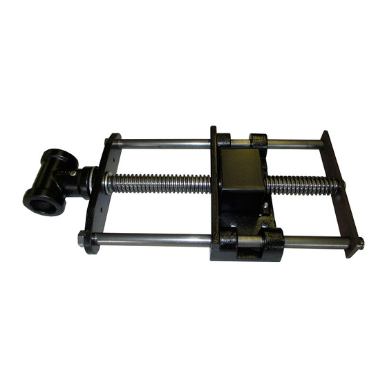
Quick-clamping system HVQ 515 and 516 (
1. Base plate
2. Face
3. Spindle
4. Nut
5. Housing
CW
CCW
Fig. 1
1. Foreword
:
Read carefully all instructions of this User Manual, especially sections concerning work safety.
These sections are marked by a warning triangle.
2. Important notice !!
- fast feed allows free motion of the screw, which can lead to pressing of fingers between the jaws!
Be CAREFUL especially during installation
- prior to use, the vice with quick-clamping system YORK-Quick must be fixed to a workbench to
enable the gravitational component to function
- the head (7) has an opening for the capstan 25-28mm (1"-5/8")
- to ensure safe fixing of the vice, the minimum workbench thickness is 30mm (5/4")
- after unpacking, the vice must be cleaned of all preservative grease and rust on the guide rods
- prior to installation, the HVQ vice must be dismantled into two parts by removing the retaining
ring (9) and brace (8) and subsequent turning the spindle clockwise (CW) until the entire base
plate (1) slides off the guide rods (6)
- assembly is done by reverse procedure and turning the spindle counter clockwise (CCW). For
centering and inserting the spindle (3) into the nut (4), it is sometimes necessary to use an
assistance tool, for example a screwdriver
- vice installation is easier when the workbench is turned upside down
- to ensure correct vice operation it is recommended to lubricate the spindle (3) and guide rods (6)
with oil once a week
see Fig. 1
6. Guide rods
7. Head with hole for capstan 28-25mm (1,1"- 0,98")
8. Brace
9. Retaining ring
2
6
7
Page 1 (of 1)
):
3
1
5
4
8
9
Advertisement

Related Manuals for York HVQ 515

Summary of Contents for York HVQ 515
- Page 1 - fast feed allows free motion of the screw, which can lead to pressing of fingers between the jaws! Be CAREFUL especially during installation - prior to use, the vice with quick-clamping system YORK-Quick must be fixed to a workbench to enable the gravitational component to function - the head (7) has an opening for the capstan 25-28mm (1“-5/8“)
-
Page 2: General Instructions
3. Standard Clamping by Turning the Spindle By turning the spindle (3) clockwise (CW) by 1.5 to 2 revolutions the nut (4) and spindle (3) engage and the screw can be tightened the standard way. 4. Fast Feed to Required Distance By turning the spindle (3) counter clockwise (CCW) by 1.5 to 2 revolutions the nut (4) and spindle (3) disengage. - Page 3 Additional front Workbench board, min. thickness 30mm (1,18“) Minimum mm/" Spacer collar height HVQ 515 40 (1,58“) 2,17 Fig. 2b 55 ( “) HVQ 516 Installation on workbench without additional rear jaw and collar – this configuration is neither usual nor recommended - Fig. 2c...
- Page 4 Tab.1 K 2xJ Fig. 3 J K mm/" mm/" mm/" mm/" mm/" mm/" mm/" mm/" Minimum Optimum HVQ 515 (1,65") (1,97") (B+0,28“) (0,20“) (5,91") (2,95") (2,95") (0,71") (1,18") B+10 HVQ 516 (2,05") (2,56") (B+0,39“) (0,47“)
- Page 5 7. Preparation of the spacer Preparation of spacer according to dimensions E, P and R – see Fig. 3 and Tab. 2 Fmin 30mm (1,18") 2° Fig.4 Spacer A+2T Total mm/" mm/" mm/" length opening Minimum Optimum Minimum Optimum E=B-F-13 200x100 C=B+50 (15,35")
- Page 6 (1) to meet with the rear jaw or workbench collar, Fig. 6 Fig.6 Fixing of base plate and spacer S S mm/" mm/" mm/" mm/" E+25 (0,24") E+35 (0,2") HVQ 515 (0,16-0,32") (E+0,98") (0,12"-0,24") (E+1,38") HVQ 516 (0,32") (0,24") Page 6 (of 6)
- Page 7 S after picture (7) . Fixing of additional front jaw S mm/" mm/" HVQ 515 (0,16"-0,24") (0,12"-0,2") HVQ 516 (0,24"-0,32") (0,2"-0,24") Fig..7 d) Finally, check the operation of the vice’s quick-automatic system. By turning the spindle (3) counter clockwise (CCW) by 1.5 to 2 revolutions the nut (4) and spindle (3) disengage.