ABB RELION 650 Series Applications Manual
Transformer protection version 2.1
Hide thumbs
Also See for RELION 650 Series:
- Technical manual (754 pages) ,
- Applications manual (382 pages) ,
- Commissioning manual (182 pages)

Related Manuals for ABB RELION 650 Series


Summary of Contents for ABB RELION 650 Series
- Page 1 — R E L I O N ® 650 SERIES Transformer protection RET650 Version 2.1 Application manual...
- Page 3 Document ID: 1MRK 504 158-UEN Issued: March 2019 Revision: A Product version: 2.1 © Copyright 2016 ABB. All rights reserved...
- Page 4 Copyright This document and parts thereof must not be reproduced or copied without written permission from ABB, and the contents thereof must not be imparted to a third party, nor used for any unauthorized purpose. The software and hardware described in this document is furnished under a license and may be used or disclosed only in accordance with the terms of such license.
- Page 5 This document has been carefully checked by ABB but deviations cannot be completely ruled out. In case any errors are detected, the reader is kindly requested to notify the manufacturer.
- Page 6 (Low-voltage directive 2006/95/EC). This conformity is the result of tests conducted by ABB in accordance with the product standard EN 60255-26 for the EMC directive, and with the product standards EN 60255-1 and EN 60255-27 for the low voltage directive. The...
-
Page 7: Table Of Contents
Table of contents Table of contents Section 1 Introduction....................... 11 This manual............................11 Intended audience..........................11 Product documentation........................12 1.3.1 Product documentation set.......................12 1.3.2 Document revision history......................13 1.3.3 Related documents........................13 Document symbols and conventions...................14 1.4.1 Symbols............................14 1.4.2 Document conventions.......................15 IEC 61850 edition 1 / edition 2 mapping..................15 Section 2 Application......................19 General IED application........................19... - Page 8 Table of contents 4.2.4.1 Example............................43 4.2.4.2 Examples how to connect, configure and set VT inputs for most commonly used VT connections....................... 43 4.2.4.3 Examples on how to connect a three phase-to-earth connected VT to the IED..44 4.2.4.4 Example on how to connect a phase-to-phase connected VT to the IED.....46 4.2.4.5 Example on how to connect an open delta VT to the IED for high impedance earthed or unearthed netwoeks...................
- Page 9 Table of contents 6.2.3.1 Setting and configuration...................... 83 6.2.3.2 Settings............................84 Section 7 Current protection................... 85 Instantaneous phase overcurrent protection PHPIOC ............85 7.1.1 Identification..........................85 7.1.2 Application............................85 7.1.3 Setting guidelines........................85 7.1.3.1 Meshed network without parallel line..................86 7.1.3.2 Meshed network with parallel line..................88 Four step phase overcurrent protection OC4PTOC..............
- Page 10 Table of contents Directional overpower protection GOPPDOP ................131 7.9.1 Identification..........................131 7.9.2 Application...........................131 7.9.3 Setting guidelines........................133 7.10 Broken conductor check BRCPTOC ................... 136 7.10.1 Identification..........................136 7.10.2 Application..........................136 7.10.3 Setting guidelines........................136 Section 8 Voltage protection..................137 Loss of voltage check LOVPTUV ....................137 8.1.1 Identification..........................
- Page 11 Table of contents 11.1.1 Identification..........................157 11.1.2 Application examples........................157 11.1.2.1 Single circuit breaker with double busbar, external voltage selection....... 158 11.1.2.2 Single circuit breaker with double busbar, internal voltage selection......158 11.1.3 Setting guidelines........................159 11.2 Apparatus control APC........................163 11.2.1 Application..........................163 11.2.1.1 Bay control (QCBAY)......................
- Page 12 Table of contents 12.1.2 Application..........................181 12.1.2.1 Three-phase tripping ......................182 12.1.2.2 Single- and/or three-phase tripping.................. 182 12.1.2.3 Single-, two- or three-phase tripping.................183 12.1.2.4 Lock-out........................... 184 12.1.2.5 Blocking of the function block.....................184 12.1.3 Setting guidelines........................184 12.2 Trip matrix logic TMAGAPC......................184 12.2.1 Identification..........................
- Page 13 Table of contents 12.13 Comparator for integer inputs - INTCOMP................194 12.13.1 Identification..........................194 12.13.2 Application..........................195 12.13.3 Setting guidelines........................195 12.13.4 Setting example......................... 195 12.14 Comparator for real inputs - REALCOMP.................. 196 12.14.1 Identification..........................196 12.14.2 Application..........................196 12.14.3 Setting guidelines........................196 12.14.4 Setting example.........................
- Page 14 Table of contents 13.7.2 Application..........................219 13.7.3 Setting guidelines........................219 13.8 Limit counter L4UFCNT........................ 219 13.8.1 Identification..........................220 13.8.2 Application..........................220 13.8.3 Setting guidelines........................220 13.9 Running hour-meter TEILGAPC....................220 13.9.1 Identification..........................220 13.9.2 Application..........................220 13.9.3 Setting guidelines........................220 Section 14 Metering......................223 14.1 Pulse-counter logic PCFCNT......................223 14.1.1 Identification..........................
- Page 15 Table of contents 15.5.1 Application..........................236 15.6 DNP3 Communication protocol....................242 15.6.1 Application..........................242 Section 16 Security......................243 16.1 Authority status ATHSTAT......................243 16.1.1 Application..........................243 16.2 Self supervision with internal event list INTERRSIG..............243 16.2.1 Application..........................243 16.3 Change lock CHNGLCK......................... 244 16.3.1 Application..........................244 16.4 Denial of service DOS........................244 16.4.1...
- Page 16 Table of contents 17.10.2 Setting guidelines........................252 17.11 Signal matrix for analog inputs SMAI..................252 17.11.1 Application..........................252 17.11.2 Frequency values........................252 17.11.3 Setting guidelines........................253 17.12 Test mode functionality TESTMODE..................257 17.12.1 Application..........................257 17.12.1.1 IEC 61850 protocol test mode.....................258 17.12.2 Setting guidelines........................
-
Page 17: Introduction
1MRK 504 158-UEN A Section 1 Introduction Section 1 Introduction This manual GUID-AB423A30-13C2-46AF-B7FE-A73BB425EB5F v19 The application manual contains application descriptions and setting guidelines sorted per function. The manual can be used to find out when and for what purpose a typical protection function can be used. -
Page 18: Product Documentation
Section 1 1MRK 504 158-UEN A Introduction Product documentation 1.3.1 Product documentation set GUID-3AA69EA6-F1D8-47C6-A8E6-562F29C67172 v15 Engineering manual Installation manual Commissioning manual Operation manual Application manual Technical manual Communication protocol manual Cyber security deployment guideline IEC07000220-4-en.vsd IEC07000220 V4 EN-US Figure 1: The intended use of manuals throughout the product lifecycle The engineering manual contains instructions on how to engineer the IEDs using the various tools available within the PCM600 software. -
Page 19: Document Revision History
1MRK 504 158-UEN A Section 1 Introduction The application manual contains application descriptions and setting guidelines sorted per function. The manual can be used to find out when and for what purpose a typical protection function can be used. The manual can also provide assistance for calculating settings. The technical manual contains operation principle descriptions, and lists function blocks, logic diagrams, input and output signals, setting parameters and technical data, sorted per function. -
Page 20: Document Symbols And Conventions
Section 1 1MRK 504 158-UEN A Introduction 650 series manuals Document numbers Accessories guide IEC: 1MRK 514 012-UEN ANSI: 1MRK 514 012-UUS Cyber security deployment guideline 1MRK 511 382-UEN Connection and Installation components 1MRK 513 003-BEN Test system, COMBITEST 1MRK 512 001-BEN Document symbols and conventions 1.4.1 Symbols... -
Page 21: Document Conventions
1MRK 504 158-UEN A Section 1 Introduction 1.4.2 Document conventions GUID-96DFAB1A-98FE-4B26-8E90-F7CEB14B1AB6 v8 • Abbreviations and acronyms in this manual are spelled out in the glossary. The glossary also contains definitions of important terms. • Push button navigation in the LHMI menu structure is presented by using the push button icons. - Page 22 Section 1 1MRK 504 158-UEN A Introduction Function block name Edition 1 logical nodes Edition 2 logical nodes EF4PTOC EF4LLN0 EF4PTRC EF4PTRC EF4RDIR EF4RDIR GEN4PHAR GEN4PHAR PH1PTOC PH1PTOC EFPIOC EFPIOC EFPIOC ETPMMTR ETPMMTR ETPMMTR FUFSPVC SDDRFUF FUFSPVC HZPDIF HZPDIF HZPDIF INDCALH INDCALH INDCALH...
- Page 23 1MRK 504 158-UEN A Section 1 Introduction Function block name Edition 1 logical nodes Edition 2 logical nodes SESRSYN RSY1LLN0 AUT1RSYN AUT1RSYN MAN1RSYN MAN1RSYN SYNRSYN SYNRSYN SINGLELCCH SCHLCCH SLGAPC SLGGIO SLGAPC SMBRREC SMBRREC SMBRREC SMPPTRC SMPPTRC SMPPTRC SP16GAPC SP16GGIO SP16GAPC SPC8GAPC SPC8GGIO SPC8GAPC...
-
Page 25: Application
1MRK 504 158-UEN A Section 2 Application Section 2 Application General IED application GUID-EB939A4F-1C88-4EB1-A217-571FEF72AC7B v2 The RET650 provides fast and selective protection, monitoring and control functions for two- and three-winding transformers, autotransformers, generator-transformer units and shunt reactors. The IED is designed to operate correctly over a wide frequency range in order to accommodate power system frequency variations during disturbances and generator startup and shutdown. -
Page 26: Main Protection Functions
Section 2 1MRK 504 158-UEN A Application management of user accounts, roles and certificates and the distribution of such, a procedure completely transparent to the user. The Flexible Product Naming allows the customer to use an IED-vendor independent 61850 model of the IED. This customer model will be used as the IEC 61850 data model, but all other aspects of the IED will remain unchanged (e.g., names on the local HMI and names in the tools). -
Page 27: Control And Monitoring Functions
1MRK 504 158-UEN A Section 2 Application Control and monitoring functions GUID-E3777F16-0B76-4157-A3BF-0B6B978863DE v13 IEC 61850 ANSI Function description Transformer RET650 (A05) Control QCBAY Apparatus control LOCREM Handling of LRswitch positions LOCREMCTRL LHMI control of PSTO SLGAPC Logic Rotating Switch for function selection and LHMI presentation VSGAPC Selector mini switch DPGAPC... - Page 28 Section 2 1MRK 504 158-UEN A Application IEC 61850 ANSI Function description Transformer RET650 (A05) REALCOMP Comparator for real inputs Monitoring CVMMXN, Measurements VMMXU, CMSQI, VMSQI, VNMMXU CMMXU Measurements AISVBAS Function block for service value presentation of secondary analog inputs SSIMG Gas medium supervision SSIML...
-
Page 29: Communication
1MRK 504 158-UEN A Section 2 Application Basic configurable logic block Total number of instances SRMEMORY TIMERSET Communication GUID-5F144B53-B9A7-4173-80CF-CD4C84579CB5 v13 IEC 61850 ANSI Function description Transformer RET650 (A05) Station communication LONSPA, SPA SPA communication protocol LON communciation protocol HORZCOMM Network variables via LON PROTOCOL Operation selection between SPA and IEC 60870-5-103 for SLM RS485PROT... -
Page 30: Basic Ied Functions
Section 2 1MRK 504 158-UEN A Application IEC 61850 ANSI Function description Transformer RET650 (A05) LPHD Physical device information PCMACCS IED configuration protocol SECALARM Component for mapping security events on protocols such as DNP3 and IEC103 FSTACCS, Field service tool access via SPA protocol over ethernet FSTACCSNA communication ACTIVLOG... - Page 31 1MRK 504 158-UEN A Section 2 Application IEC 61850 or function Description name SPACOMMMAP SPA communication mapping SPATD Date and time via SPA protocol DOSFRNT Denial of service, frame rate control for front port DOSLANAB Denial of service, frame rate control for OEM port AB DOSLANCD Denial of service, frame rate control for OEM port CD DOSSCKT...
-
Page 33: Configuration
The configurations are as far as found necessary provided with application comments to explain why the signals have been connected in the special way. On request, ABB is available to support the re-configuration work, either directly or to do the design checking. - Page 34 Section 3 1MRK 504 158-UEN A Configuration RET650 A05 – 3 Winding Transformer in single breaker arrangement 12AI (10I+2U) W1_QB1 W1_QB2 W1_QA1 Control Control Control S CILO S CSWI S XCBR 1 → 0 W1_QA1 DFR/SER DR SMP PTRC DRP RDRE W1_CT 50BF 3I>BF 4(3I>)
-
Page 35: Analog Inputs
1MRK 504 158-UEN A Section 4 Analog inputs Section 4 Analog inputs Introduction SEMOD55003-5 v10 Analog input channels must be configured and set properly in order to get correct measurement results and correct protection operations. For power measuring and all directional and differential functions the directions of the input currents must be defined in order to reflect the way the current transformers are installed/connected in the field ( primary and secondary connections ). -
Page 36: Setting Of Current Channels
Section 4 1MRK 504 158-UEN A Analog inputs 4.2.2 Setting of current channels SEMOD55055-16 v5 The direction of a current to the IED is depending on the connection of the CT. Unless indicated otherwise, the main CTs are supposed to be star connected and can be connected with the earthing point to the object or from the object. -
Page 37: Example 2
1MRK 504 158-UEN A Section 4 Analog inputs Line Transformer Line Reverse Forward Definition of direction for directional functions Transformer protection Line protection Setting of current input: Setting of current input: Setting of current input: Set parameter Set parameter Set parameter CTStarPoint with CTStarPoint with CTStarPoint with... -
Page 38: Example 3
Section 4 1MRK 504 158-UEN A Analog inputs Transformer Line Reverse Forward Definition of direction for directional functions Transformer protection Line protection Setting of current input: Setting of current input: Setting of current input: Set parameter Set parameter Set parameter CTStarPoint with CTStarPoint with CTStarPoint with... - Page 39 1MRK 504 158-UEN A Section 4 Analog inputs Transformer Line Forward Reverse Definition of direction for directional Transformer and line functions Line protection Setting of current input: Setting of current input: Set parameter Set parameter CTStarPoint with CTStarPoint with Transformer as Transformer as reference object.
-
Page 40: Examples On How To Connect, Configure And Set Ct Inputs For Most Commonly Used Ct Connections
Section 4 1MRK 504 158-UEN A Analog inputs Transformer Line Reverse Forward Definition of direction for directional Transformer and line functions Line protection Setting of current input for line functions: Set parameter CTStarPoint with Line as reference object. Setting of current input Setting of current input Correct setting is for transformer functions:... -
Page 41: Example On How To Connect A Star Connected Three-Phase Ct Set To The Ied
1MRK 504 158-UEN A Section 4 Analog inputs Where: is symbol and terminal marking used in this document. Terminals marked with a square indicates the primary and secondary winding terminals with the same (that is, positive) polarity b) and are equivalent symbols and terminal marking used by IEC (ANSI) standard for CTs. Note that for these two cases the CT polarity marking is correct! It shall be noted that depending on national standard and utility practices, the rated secondary current of a CT has typically one of the following values:... - Page 42 Section 4 1MRK 504 158-UEN A Analog inputs CT 600/5 SMAI2 BLOCK AI3P Star Connected REVROT ^GRP2L1 ^GRP2L2 ^GRP2L3 ^GRP2N IEC13000002-4-en.vsdx Protected Object IEC13000002 V4 EN-US Figure 9: Star connected three-phase CT set with star point towards the protected object Where: The drawing shows how to connect three individual phase currents from a star connected three- phase CT set to the three CT inputs of the IED.
- Page 43 1MRK 504 158-UEN A Section 4 Analog inputs These three connections are the links between the three current inputs and the three input channels of the preprocessing function block 4). Depending on the type of functions, which need this current information, more than one preprocessing block might be connected in parallel to the same three physical CT inputs.
- Page 44 Section 4 1MRK 504 158-UEN A Analog inputs CTprim =600A • • CTsec =5A CTStarPoint =FromObject • Inside the IED only the ratio of the first two parameters is used. The third parameter as set in this example will negate the measured currents in order to ensure that the currents are measured towards the protected object within the IED.
-
Page 45: Example How To Connect Delta Connected Three-Phase Ct Set To The Ied
1MRK 504 158-UEN A Section 4 Analog inputs are three connections made in the Signal Matrix tool (SMT), Application configuration tool (ACT), which connects these three current inputs to the first three input channels on the preprocessing function block 6). Depending on the type of functions, which need this current information, more than one preprocessing block might be connected in parallel to these three CT inputs. - Page 46 Section 4 1MRK 504 158-UEN A Analog inputs IL1-IL2 SMAI2 BLOCK AI3P IL2-IL3 REVROT ^GRP2L1 IL3-IL1 ^GRP2L2 ^GRP2L3 ^GRP2N IEC11000027-3-en.vsdx Protected Object IEC11000027 V3 EN-US Figure 12: Delta DAB connected three-phase CT set Where: shows how to connect three individual phase currents from a delta connected three-phase CT set to three CT inputs of the IED.
-
Page 47: Example How To Connect Single-Phase Ct To The Ied
1MRK 504 158-UEN A Section 4 Analog inputs Another alternative is to have the delta connected CT set as shown in figure 13: IL1-IL3 SMAI2 BLOCK AI3P REVROT IL2-IL1 ^GRP2L1 ^GRP2L2 IL3-IL2 ^GRP2L3 ^GRP2N IEC11000028-3-en.vsdx Protected Object IEC11000028 V3 EN-US Figure 13: Delta DAC connected three-phase CT set In this case, everything is done in a similar way as in the above described example, except that... -
Page 48: Relationships Between Setting Parameter Base Current, Ct Rated Primary Current And Minimum Pickup Of A Protection Ied
Section 4 1MRK 504 158-UEN A Analog inputs Protected Object SMAI2 BLOCK AI3P REVROT ^GRP2L1 ^GRP2L2 ^GRP2L3 ^GRP2N IEC11000029-4-en.vsdx IEC11000029 V4 EN-US Figure 14: Connections for single-phase CT input Where: shows how to connect single-phase CT input in the IED. is TRM where these current inputs are located. -
Page 49: Setting Of Voltage Channels
1MRK 504 158-UEN A Section 4 Analog inputs CTs involved in the protection scheme. The rated CT primary current value is set as parameter CTPrim under the IED TRM settings. For all other protection applications (e.g. generator, shunt reactor, shunt capacitor and IBase parameter equal to the rated transformer protection) it is typically desirable to set current of the protected object. -
Page 50: Examples On How To Connect A Three Phase-To-Earth Connected Vt To The Ied
Section 4 1MRK 504 158-UEN A Analog inputs (X1) (X1) (X1) (H1) (H1) (H1) (H2) (X2) (H2) (X2) (H2) (X2) en06000591.vsd IEC06000591 V1 EN-US Figure 15: Commonly used markings of VT terminals Where: is the symbol and terminal marking used in this document. Terminals marked with a square indicate the primary and secondary winding terminals with the same (positive) polarity is the equivalent symbol and terminal marking used by IEC (ANSI) standard for phase-to-earth connected VTs... - Page 51 1MRK 504 158-UEN A Section 4 Analog inputs SMAI2 BLOCK AI3P REVROT ^GRP2L1 ^GRP2L2 ^GRP2L3 ^GRP2N #Not used IEC06000599-4-en.vsdx IEC06000599 V4 EN-US Figure 16: A Three phase-to-earth connected VT Where: shows how to connect three secondary phase-to-earth voltages to three VT inputs on the IED is the TRM where these three voltage inputs are located.
-
Page 52: Example On How To Connect A Phase-To-Phase Connected Vt To The Ied
Section 4 1MRK 504 158-UEN A Analog inputs are three connections made in Signal Matrix Tool (SMT), which connect these three voltage inputs to first three input channels of the preprocessing function block 5). Depending on the type of functions which need this voltage information, more then one preprocessing block might be connected in parallel to these three VT inputs. - Page 53 1MRK 504 158-UEN A Section 4 Analog inputs 13.8 13.8 SMAI2 BLOCK AI3P REVROT ^GRP2L1 ^GRP2L2 ^GRP2L3 #Not Used ^GRP2N IEC06000600-5-en.vsdx IEC06000600 V5 EN-US Figure 17: A Two phase-to-phase connected VT Where: shows how to connect the secondary side of a phase-to-phase VT to the VT inputs on the IED is the TRM where these three voltage inputs are located.
-
Page 54: Example On How To Connect An Open Delta Vt To The Ied For High Impedance Earthed Or Unearthed Netwoeks
Section 4 1MRK 504 158-UEN A Analog inputs 4.2.4.5 Example on how to connect an open delta VT to the IED for high impedance earthed or unearthed netwoeks SEMOD55055-163 v8 Figure gives an example about the wiring of an open delta VT to the IED for high impedance earthed or unearthed power systems. -
Page 55: Example How To Connect The Open Delta Vt To The Ied For Low Impedance Earthed Or Solidly Earthed Power Systems
1MRK 504 158-UEN A Section 4 Analog inputs Where: shows how to connect the secondary side of the open delta VT to one VT input on the IED. +3U0 shall be connected to the IED is the TRM where this voltage input is located. It shall be noted that for this voltage input the following setting values shall be entered: ×... - Page 56 Section 4 1MRK 504 158-UEN A Analog inputs Ph Ph Ph E (Equation 7) EQUATION1926 V1 EN-US The primary rated voltage of such VT is always equal to UPh-E Therefore, three series connected VT secondary windings will give the secondary voltage equal only to one individual VT secondary winding rating.
-
Page 57: Example On How To Connect A Neutral Point Vt To The Ied
1MRK 504 158-UEN A Section 4 Analog inputs Where: shows how to connect the secondary side of open delta VT to one VT input in the IED. +3Uo shall be connected to the IED. is TRM where this voltage input is located. It shall be noted that for this voltage input the following setting values shall be entered: ×... - Page 58 Section 4 1MRK 504 158-UEN A Analog inputs In case of a solid earth fault in high impedance earthed or unearthed systems the primary value of Uo voltage will be equal to: (Equation 11) EQUATION1931 V2 EN-US Figure 20gives an overview of required actions by the user in order to make this measurement available to the built-in protection and control functions within the IED.
- Page 59 1MRK 504 158-UEN A Section 4 Analog inputs shows that in this example the first three input channel of the preprocessing block is not connected in SMT tool or ACT tool. shows the connection made in Signal Matrix Tool (SMT), Application configuration tool (ACT), which connects this voltage input to the fourth input channel of the preprocessing function block 5).
-
Page 61: Local Hmi
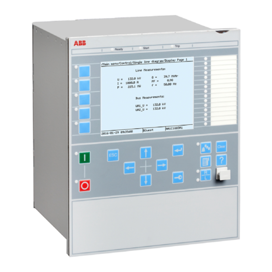
1MRK 504 158-UEN A Section 5 Local HMI Section 5 Local HMI AMU0600442 v14 IEC13000239-2-en.vsd IEC13000239 V2 EN-US Figure 21: Local human-machine interface The LHMI of the IED contains the following elements: • Keypad • Display (LCD) • LED indicators •... -
Page 62: Display
Section 5 1MRK 504 158-UEN A Local HMI Display GUID-55739D4F-1DA5-4112-B5C7-217AAF360EA5 v11 The LHMI includes a graphical monochrome liquid crystal display (LCD) with a resolution of 320 x 240 pixels. The character size can vary. The amount of characters and rows fitting the view depends on the character size and the view that is shown. -
Page 63: Leds
1MRK 504 158-UEN A Section 5 Local HMI IEC13000281-1-en.vsd GUID-C98D972D-D1D8-4734-B419-161DBC0DC97B V1 EN-US Figure 23: Function button panel The indication LED panel shows on request the alarm text labels for the indication LEDs. Three indication LED pages are available. IEC13000240-1-en.vsd GUID-5157100F-E8C0-4FAB-B979-FD4A971475E3 V1 EN-US Figure 24: Indication LED panel The function button and indication LED panels are not visible at the same time. -
Page 64: Keypad
Section 5 1MRK 504 158-UEN A Local HMI three LED groups. The LEDs are lit according to priority, with red being the highest and green the lowest priority. For example, if on one panel there is an indication that requires the green LED to be lit, and on another panel there is an indication that requires the red LED to be lit, the red LED takes priority and is lit. - Page 65 1MRK 504 158-UEN A Section 5 Local HMI IEC15000157-2-en.vsd IEC15000157 V2 EN-US Figure 25: LHMI keypad with object control, navigation and command push-buttons and RJ-45 communication port 1...5 Function button Close Open Escape Left Down Right Enter Remote/Local Uplink LED Not in use Multipage Menu...
-
Page 66: Local Hmi Functionality
Section 5 1MRK 504 158-UEN A Local HMI Communication port Programmable indication LEDs IED status LEDs Local HMI functionality 5.4.1 Protection and alarm indication GUID-09CCB9F1-9B27-4C12-B253-FBE95EA537F5 v15 Protection indicators The protection indicator LEDs are Ready, Start and Trip. The start and trip LEDs are configured via the disturbance recorder. The yellow and red status LEDs are configured in the disturbance recorder function, DRPRDRE, by connecting a start or trip signal from the actual function to a BxRBDR binary input function block using the PCM600 and configure the... -
Page 67: Parameter Management
1MRK 504 158-UEN A Section 5 Local HMI Table 8: Trip LED (red) LED state Description Normal operation. A protection function has tripped. An indication message is displayed if the auto-indication feature is enabled in the local HMI. The trip indication is latching and must be reset via communication, LHMI or binary input on the LEDGEN component. - Page 68 Section 5 1MRK 504 158-UEN A Local HMI IEC13000280-1-en.vsd GUID-AACFC753-BFB9-47FE-9512-3C4180731A1B V1 EN-US Figure 26: RJ-45 communication port and green indicator LED 1 RJ-45 connector 2 Green indicator LED The default IP address for the IED front port is 10.1.150.3 and the corresponding subnetwork mask is 255.255.255.0.
-
Page 69: Differential Protection
1MRK 504 158-UEN A Section 6 Differential protection Section 6 Differential protection Transformer differential protection T3WPDIF IP14639-1 v3 6.1.1 Application M16722-3 v9 The transformer differential protection is a unit protection. It serves as the main protection of transformers in case of winding failure. The protective zone of a differential protection includes the transformer itself, the bus-work or cables between the current transformers and the power transformer. -
Page 70: Setting Guidelines
Section 6 1MRK 504 158-UEN A Differential protection The three winding transformer differential protection function can be also used in variety of application for two winding transformer protection. In such application, it is suggested to set the tertiary winding (W3) rated current and rated voltage to the exact same rating as secondary winding (W2). - Page 71 1MRK 504 158-UEN A Section 6 Differential protection Transformers can be connected to buses in such ways that the current transformers used for the differential protection will be either in series with the power transformer windings or the current transformers will be in breakers that are part of the bus, such as a breaker-and-a-half or a ring bus scheme.
-
Page 72: Elimination Of Zero Sequence Currents
Section 6 1MRK 504 158-UEN A Differential protection operate current [ times IBase ] Operate unconditionally UnrestrainedLimit Operate conditionally Section 1 Section 2 Section 3 SlopeSection3 IdMin SlopeSection2 Restrain EndSection1 restrain current [ times IBase ] EndSection2 en05000187-2.vsd IEC05000187 V2 EN-US Figure 27: Representation of the restrained, and the unrestrained operate characteristics Ioperate... -
Page 73: Inrush Restraint Methods
1MRK 504 158-UEN A Section 6 Differential protection transformer, which may result in differential current as well. To make the overall differential protection insensitive to external earth-faults in these situations the zero sequence currents must be eliminated from the power transformer IED currents on the earthed windings, so that they do not appear as differential currents. -
Page 74: External/Internal Fault Discriminator
Section 6 1MRK 504 158-UEN A Differential protection 6.1.2.6 External/Internal fault discriminator M15266-269 v10 The external/internal fault discriminator operation is based on the relative position of the two phasors (in case of a two-winding transformer) representing the W1 and W2 negative sequence current contributions, defined by matrix expression see the technical reference manual. -
Page 75: Differential Current Alarm
1MRK 504 158-UEN A Section 6 Differential protection External faults happen ten to hundred times more often than internal ones as far as the power transformers are concerned. If a disturbance is detected and the internal/external fault discriminator characterizes this fault as an external fault, the conventional additional criteria are posed on the differential algorithm before its trip is allowed. -
Page 76: Switch Onto Fault Feature
Section 6 1MRK 504 158-UEN A Differential protection OpenCT : Open CT detected • • OpenCTAlarm : Alarm issued after the setting delay OpenCTIN : Open CT in CT group inputs (1 for input 1 and 2 for input 2) •... -
Page 77: Typical Main Ct Connections For Transformer Differential Protection
1MRK 504 158-UEN A Section 6 Differential protection 6.1.3.2 Typical main CT connections for transformer differential protection SEMOD167749-5 v3 Three most typical main CT connections used for transformer differential protection are shown in figure 28. It is assumed that the primary phase sequence is L1-L2-L3. Protected Transformer Winding... -
Page 78: Application Examples
Section 6 1MRK 504 158-UEN A Differential protection For DAB delta connected main CT ratio shall be set for √3 times smaller in RET 670 then the actual ratio of individual phase CTs. The “StarPoint” parameter, for this particular connection ToObject . - Page 79 1MRK 504 158-UEN A Section 6 Differential protection CT 300/5 CT 300/5 in Delta Star (DAC) 20.9 MVA 20.9 MVA 69/12.5 kV 69/12.5 kV YNd1 YNd1 CT 800/5 CT 800/5 Star Star en06000554.vsd IEC06000554 V1 EN-US Figure 29: Two differential protection solutions for star-delta connected power transformer For this particular power transformer the 69 kV side phase-to-earth no-load voltages lead by 30 degrees the 12.5 kV side phase-to- earth no-load voltages.
- Page 80 Section 6 1MRK 504 158-UEN A Differential protection 5. Enter the following settings for all three CT input channels used for the HV side CTs, see table 11. Table 11: CT input channels used for the HV side CTs Setting parameter Selected value for solution 1 Selected value for solution 2 (delta (star connected CT)
- Page 81 1MRK 504 158-UEN A Section 6 Differential protection CT 400/5 CT 400/5 Star Star 60 MVA 60 MVA 115/24.9 kV 115/24.9 kV Dyn1 Dyn1 CT 1500/5 CT 1500/5 in Delta Star (DAB) en06000555.vsd IEC06000555 V1 EN-US Figure 30: Two differential protection solutions for delta-star connected power transformer For this particular power transformer the 115 kV side phase-to-earth no-load voltages lead by 30°...
-
Page 82: Summary And Conclusions
Section 6 1MRK 504 158-UEN A Differential protection CT input channels used for the LV side CTs Setting parameter Selected value for Solution 1 Selected value for Solution 2 (delta (star connected CT) connected CT) CTprim 1500 1500 (Equation 16) EQUATION1889 V1 EN-US CTsec CTStarPoint... - Page 83 1MRK 504 158-UEN A Section 6 Differential protection The ratio for delta connected CTs shall be set √(3)=1.732 times smaller than the actual individual phase CT ratio. The power transformer vector group shall typically be set as Yy0 because the compensation for power transformer the actual phase shift is provided by the external delta CT connection.
-
Page 84: Low Impedance Restricted Earth Fault Protection Refpdif
Section 6 1MRK 504 158-UEN A Differential protection IEC vector group Positive sequence no-load Required delta CT connection type on star side of the voltage phasor diagram protected power transformer and internal vector group setting in the IED Dyn11 DAC/Yy0 IEC06000562 V1 EN-US YNd5 DAB/Yy6... -
Page 85: Transformer Winding, Solidly Earthed
1MRK 504 158-UEN A Section 6 Differential protection The only requirement is that the power transformer winding is connected to earth in the star point (in case of star-connected windings) or through a separate earthing transformer (in case of delta-connected windings). The low impedance restricted earth-fault protection REFPDIF is a winding protection function. -
Page 86: Transformer Winding, Earthed Through Zig-Zag Earthing Transformer
Section 6 1MRK 504 158-UEN A Differential protection REFPDIF I3PW1CT1 IdN/I Protected winding IEC09000109-4-EN.vsd IEC09000109-4-EN V2 EN-US Figure 31: Connection of the low impedance Restricted earth-fault function REFPDIF for a directly (solidly) earthed transformer winding 6.2.2.2 Transformer winding, earthed through zig-zag earthing transformer M13048-8 v11 A common application is for low reactance earthed transformer where the earthing is through separate zig-zag earthing transformers. -
Page 87: Autotransformer Winding, Solidly Earthed
1MRK 504 158-UEN A Section 6 Differential protection REFPDIF I3PW1CT1 IdN/I Protected winding W1 REFPDIF I3PW2CT1 Protected IdN/I winding W2 Earthing transformer IEC09000110-4-EN.vsd IEC09000110-4-EN V2 EN-US Figure 32: Connection of the low impedance Restricted earth-fault function REFPDIF for a zig-zag earthing transformer 6.2.2.3 Autotransformer winding, solidly earthed M13048-13 v9... -
Page 88: Reactor Winding, Solidly Earthed
Section 6 1MRK 504 158-UEN A Differential protection REFPDIF HV (W1) I3PW1CT1 I3PW2CT1 IdN/I LV (W2) Auto transformer IEC09000111-4-EN.vsd IEC09000111-4-EN V2 EN-US Figure 33: Connection of restricted earth fault, low impedance function REFPDIF for an autotransformer, solidly earthed 6.2.2.4 Reactor winding, solidly earthed M13048-18 v10 Reactors can be protected with restricted earth-fault protection, low impedance function REFPDIF. -
Page 89: Ct Earthing Direction
1MRK 504 158-UEN A Section 6 Differential protection REFPDIF I3PW1CT1 IdN/I Reactor IEC09000112-4.vsd IEC09000112-4 V2 EN-US Figure 34: Connection of restricted earth-fault, low impedance function REFPDIF for a solidly earthed reactor 6.2.2.5 CT earthing direction M13048-29 v12 To make the restricted earth-fault protection REFPDIF operate correctly, the main CTs are always supposed to be star -connected. -
Page 90: Settings
Section 6 1MRK 504 158-UEN A Differential protection I3PW2CT1: Phase currents for winding 2 first current transformer set. Used for autotransformers. I3PW2CT2: Phase currents for winding 2 second current transformer set for multi-breaker arrangements. Used when protecting an autotransformer. When not required, configure input to "GRP-OFF". -
Page 91: Current Protection
1MRK 504 158-UEN A Section 7 Current protection Section 7 Current protection Instantaneous phase overcurrent protection PHPIOC IP14506-1 v6 7.1.1 Identification M14880-1 v4 Function description IEC 61850 IEC 60617 ANSI/IEEE C37.2 identification identification device number Instantaneous phase overcurrent PHPIOC protection 3-phase output 3I>>... -
Page 92: Meshed Network Without Parallel Line
Section 7 1MRK 504 158-UEN A Current protection Only detailed network studies can determine the operating conditions under which the highest possible fault current is expected on the line. In most cases, this current appears during three-phase fault conditions. But also examine single-phase-to-earth and two-phase- to-earth conditions. - Page 93 1MRK 504 158-UEN A Section 7 Current protection Fault IEC09000023-1-en.vsd IEC09000023 V1 EN-US Figure 36: Through fault current from B to A: I The IED must not trip for any of the two through-fault currents. Hence the minimum theoretical current setting (Imin) will be: ³...
-
Page 94: Meshed Network With Parallel Line
Section 7 1MRK 504 158-UEN A Current protection 7.1.3.2 Meshed network with parallel line M12915-34 v6 In case of parallel lines, the influence of the induced current from the parallel line to the protected line has to be considered. One example is given in figure where the two lines are connected to the same busbars. -
Page 95: Four Step Phase Overcurrent Protection Oc4Ptoc
1MRK 504 158-UEN A Section 7 Current protection Four step phase overcurrent protection OC4PTOC SEMOD129998-1 v7 7.2.1 Identification M14885-1 v5 Function description IEC 61850 IEC 60617 ANSI/IEEE C37.2 identification identification device number Four step phase overcurrent OC4PTOC 51_67 protection 3-phase output TOC-REVA V2 EN-US 7.2.2 Application... -
Page 96: Setting Guidelines
Section 7 1MRK 504 158-UEN A Current protection to the current pick-up level. This multiplication factor is activated from a binary input signal to the function. Power transformers can have a large inrush current, when being energized. This phenomenon is due to saturation of the transformer magnetic core during parts of the period. There is a risk that inrush current will reach levels above the pick-up current of the phase overcurrent protection. -
Page 97: Settings For Each Step
1MRK 504 158-UEN A Section 7 Current protection IEC09000636_1_vsd IEC09000636 V1 EN-US Figure 39: Directional function characteristic RCA = Relay characteristic angle ROA = Relay operating angle Reverse Forward 7.2.3.1 Settings for each step M12982-19 v10.1.1 x means step 1, 2, 3 and 4. DirModex : The directional mode of step x . - Page 98 Section 7 1MRK 504 158-UEN A Current protection Curve name ANSI Moderately Inverse ANSI/IEEE Definite time ANSI Long Time Extremely Inverse ANSI Long Time Very Inverse ANSI Long Time Inverse IEC Normal Inverse IEC Very Inverse IEC Inverse IEC Extremely Inverse IEC Short Time Inverse IEC Long Time Inverse IEC Definite Time...
- Page 99 1MRK 504 158-UEN A Section 7 Current protection Operate time txMin IMinx Current IEC10000058 IEC10000058 V2 EN-US Figure 40: Minimum operate current and operate time for inverse time characteristics txMin shall be In order to fully comply with the definition of the curve, the setting parameter set to a value equal to the operating time of the selected inverse curve for twenty times the set current pickup value.
-
Page 100: 2Nd Harmonic Restrain
Section 7 1MRK 504 158-UEN A Current protection æ ö ç ÷ ç ÷ × IxMult ç ÷ æ ö ç ç ÷ ÷ è è ø ø > (Equation 23) EQUATION1261 V2 EN-US tPRCrvx , tTRCrvx , tCRCrvx : These parameters are used by the customer to create the inverse Technical manual . - Page 101 1MRK 504 158-UEN A Section 7 Current protection Current I Line phase current Operate current Reset current The IED does not reset Time t IEC05000203-en-2.vsd IEC05000203 V3 EN-US Figure 41: Operate and reset current for an overcurrent protection The lowest setting value can be written according to equation 24. Im ax ³...
- Page 102 Section 7 1MRK 504 158-UEN A Current protection £ × 0.7 Isc min (Equation 25) EQUATION1263 V2 EN-US where: is a safety factor Iscmin is the smallest fault current to be detected by the overcurrent protection. As a summary the operating current shall be chosen within the interval stated in equation 26. Im ax ×...
- Page 103 1MRK 504 158-UEN A Section 7 Current protection en05000204.wmf IEC05000204 V1 EN-US Figure 42: Fault time with maintained selectivity The operation time can be set individually for each overcurrent protection. To assure selectivity between different protections, in the radial network, there have to be a minimum time difference Dt between the time delays of two protections.
-
Page 104: Instantaneous Residual Overcurrent Protection Efpioc
Section 7 1MRK 504 158-UEN A Current protection Feeder I> I> Time axis The fault Protection Breaker at Protection occurs B1 trips B1 opens A1 resets en05000205.vsd IEC05000205 V1 EN-US Figure 43: Sequence of events during fault where: is when the fault occurs is when the trip signal from the overcurrent protection at IED B1 is sent to the circuit breaker. -
Page 105: Identification
1MRK 504 158-UEN A Section 7 Current protection 7.3.1 Identification M14887-1 v4 Function description IEC 61850 IEC 60617 ANSI/IEEE C37.2 identification identification device number Instantaneous residual overcurrent EFPIOC protection IN>> IEF V1 EN-US 7.3.2 Application M12699-3 v5 In many applications, when fault current is limited to a defined value by the object impedance, an instantaneous earth-fault protection can provide fast and selective tripping. - Page 106 Section 7 1MRK 504 158-UEN A Current protection Fault IEC09000023-1-en.vsd IEC09000023 V1 EN-US Figure 45: Through fault current from B to A: I The function shall not operate for any of the calculated currents to the protection. The minimum theoretical current setting (Imin) will be: ³...
-
Page 107: Four Step Residual Overcurrent Protection Ef4Ptoc
1MRK 504 158-UEN A Section 7 Current protection ³ I m in M A X I (Equation 31) EQUATION287 V1 EN-US Where: and I have been described for the single line case. Considering the safety margins mentioned previously, the minimum setting (Is) is: = 1.3 ×... - Page 108 Section 7 1MRK 504 158-UEN A Current protection In many applications several steps with different current operating levels and time delays are needed. EF4PTOC can have up to four, individual settable steps. The flexibility of each step of EF4PTOC is great. The following options are possible: Non-directional/Directional function: In some applications the non-directional functionality is used.
-
Page 109: Setting Guidelines
1MRK 504 158-UEN A Section 7 Current protection to the residual current pick-up level. This multiplication factor is activated from a binary input signal ENMULTx to the function. Power transformers can have a large inrush current, when being energized. This inrush current can have residual current components. - Page 110 Section 7 1MRK 504 158-UEN A Current protection Protection operate time: 15-60 ms Protection resetting time: 15-60 ms Breaker opening time: 20-120 ms The different characteristics are described in the technical reference manual. tx : Definite time delay for step x . The definite time tx is added to the inverse time when inverse time characteristic is selected.
-
Page 111: Common Settings For All Steps
1MRK 504 158-UEN A Section 7 Current protection tResetx : Constant reset time delay in s for step x. HarmBlockx : This is used to enable block of step x from 2 harmonic restrain function. tPCrvx, tACrvx, tBCrvx, tCCrvx : Parameters for user programmable of inverse time characteristic curve. -
Page 112: 2Nd Harmonic Restrain
Section 7 1MRK 504 158-UEN A Current protection Voltage (3U • or U Current (3I • · ZNpol or 3I ·ZNpol where ZNpol is RNpol + jXNpol), or Dual (dual polarizing, (3U • both currents and voltage, + 3I · ZNpol) or (U ·... -
Page 113: Switch Onto Fault Logic
1MRK 504 158-UEN A Section 7 Current protection of the two transformers will be in phase opposition. The summation of the two currents will thus give a small 2 harmonic current. The residual fundamental current will however be significant. The inrush current of the transformer in service before the parallel transformer energizing, will be a little delayed compared to the first transformer. -
Page 114: Transformer Application Example
Section 7 1MRK 504 158-UEN A Current protection ActivationSOTF : This setting will select the signal to activate SOTF function; CB position open/CB position closed/CB close command . tSOTF : Time delay for operation of the SOTF function. The setting range is 0.000 - 60.000 s in step of 0.001 s. - Page 115 1MRK 504 158-UEN A Section 7 Current protection It can be suitable to use a residual overcurrent protection with at least two steps. Step 1 shall have a short definite time delay and a relatively high current setting, in order to detect and clear high current earth faults in the transformer winding or in the power system close to the transformer.
- Page 116 Section 7 1MRK 504 158-UEN A Current protection YN/D or YN/Y transformer Three phase CT summated Single CT > Single phase-to- earth fault IEC05000492-en-2.vsd IEC05000492 V2 EN-US Figure 52: Step 1 fault calculation 1 This calculation gives the current fed to the protection: 3I 0fault1 To assure that step 1, selectivity to other earth-fault protections in the network a short delay is selected.
-
Page 117: Sensitive Directional Residual Overcurrent And Power Protection Sdepsde
1MRK 504 158-UEN A Section 7 Current protection × < < × lowmar highmar 0fault 2 step1 0fault1 (Equation 34) EQUATION1455 V2 EN-US Where: lowmar is a margin to assure selectivity (typical 1.2) and highmar is a margin to assure fast fault clearance of busbar fault (typical 1.2). Setting of step 2 SEMOD55591-57 v4 The setting of the sensitive step 2 is dependent of the chosen time delay. - Page 118 Section 7 1MRK 504 158-UEN A Current protection A backup neutral point voltage function is also available for non-directional residual overvoltage protection. In an isolated network, that is, the network is only coupled to earth via the capacitances between the phase conductors and earth, the residual current always has -90º phase shift compared to the residual voltage (3U ).
-
Page 119: Setting Guidelines
1MRK 504 158-UEN A Section 7 Current protection 7.5.3 Setting guidelines SEMOD171961-4 v9 The sensitive earth fault protection is intended to be used in high impedance earthed systems, or in systems with resistive earthing where the neutral point resistor gives an earth fault current larger than what normal high impedance gives but smaller than the phase-to-phase short circuit current. - Page 120 Section 7 1MRK 504 158-UEN A Current protection × jX 3R (Equation 38) EQUATION1946 V1 EN-US Where is the resistance of the neutral point resistor In many systems there is also a neutral point reactor (Petersen coil) connected to one or more transformer neutral points.
- Page 121 1MRK 504 158-UEN A Section 7 Current protection phase × + × (Equation 40) EQUATION1948 V1 EN-US Where is the phase voltage in the fault point before the fault phase is the total positive sequence impedance to the fault point. Z lineAB,1 lineBC,1 is the total zero sequence impedance to the fault point.
- Page 122 Section 7 1MRK 504 158-UEN A Current protection × × × kSN (3I 3U cos (reference)) × × 3I 3U cos (measured) (Equation 47) EQUATION1942 V2 EN-US On/Off with the setting of Operation . The function can be set Common base IED values for primary current (IBase), primary voltage (UBase) and primary power (SBase) are set in a Global base values for settings function GBASVAL.
- Page 123 1MRK 504 158-UEN A Section 7 Current protection RCADir = − 90 , ROADir 3 ⋅ ϕ ϕ = ang I (3 ) − ang U − IEC06000649_3_en.vsd IEC06000649 V3 EN-US Figure 57: Characteristic for RCADir equal to -90° When OpMode is set to 3U03I0cosfi the apparent residual power component in the direction is measured.
- Page 124 Section 7 1MRK 504 158-UEN A Current protection UNRel> which All the directional protection modes have a residual voltage release level setting is set in % of UBase . This setting should be chosen smaller than or equal to the lowest fault residual voltage to be detected.
-
Page 125: Thermal Overload Protection, Two Time Constants Trpttr
1MRK 504 158-UEN A Section 7 Current protection Table 18: Inverse time characteristics Curve name ANSI Extremely Inverse ANSI Very Inverse ANSI Normal Inverse ANSI Moderately Inverse ANSI/IEEE Definite time ANSI Long Time Extremely Inverse ANSI Long Time Very Inverse ANSI Long Time Inverse IEC Normal Inverse IEC Very Inverse... -
Page 126: Identification
Section 7 1MRK 504 158-UEN A Current protection 7.6.1 Identification M14877-1 v2 Function description IEC 61850 IEC 60617 ANSI/IEEE C37.2 identification identification device number Thermal overload protection, two TRPTTR time constants SYMBOL-A V1 EN-US 7.6.2 Application M15341-3 v5 Transformers in the power system are designed for a certain maximum load current (power) level. -
Page 127: Setting Guideline
1MRK 504 158-UEN A Section 7 Current protection 7.6.3 Setting guideline M13250-3 v8 The parameters for the thermal overload protection, two time constants (TRPTTR) are set via the local HMI or Protection and Control IED Manager (PCM600). The following settings can be done for the thermal overload protection: Operation : Off / On Operation : Sets the mode of operation. -
Page 128: Breaker Failure Protection Ccrbrf
Section 7 1MRK 504 158-UEN A Current protection The time constants can be changed if the current is higher than a set value or lower than a set value. If the current is high it is assumed that the forced cooling is activated while it is deactivated at low current. -
Page 129: Identification
1MRK 504 158-UEN A Section 7 Current protection 7.7.1 Identification M14878-1 v5 Function description IEC 61850 IEC 60617 ANSI/IEEE C37.2 identification identification device number Breaker failure protection, 3-phase CCRBRF 50BF activation and output 3I>BF SYMBOL-U V1 EN-US 7.7.2 Application M13916-3 v6 In the design of the fault clearance system the N-1 criterion is often used. - Page 130 Section 7 1MRK 504 158-UEN A Current protection Table 19: Dependencies between parameters RetripMode and FunctionMode RetripMode FunctionMode Description Retrip Off the re-trip function is not activated CB Pos Check Current re-trip is done if phase current is larger than the operate level after re-trip time has elapsed Contact re-trip is done when auxiliary...
- Page 131 1MRK 504 158-UEN A Section 7 Current protection The minimum time delay for the re-trip can be estimated as: ³ cbopen BFP reset margin (Equation 51) EQUATION1430 V1 EN-US where: is the maximum opening time for the circuit breaker cbopen is the maximum time for breaker failure protection to detect correct breaker function BFP_reset (the current criteria reset)
-
Page 132: Directional Underpower Protection Guppdup
Section 7 1MRK 504 158-UEN A Current protection tPulse : Trip pulse duration. This setting must be larger than the critical impulse time of circuit breakers to be tripped from the breaker failure protection. Typical setting is 200 ms. Directional underpower protection GUPPDUP SEMOD156693-1 v4 7.8.1 Identification... -
Page 133: Setting Guidelines
1MRK 504 158-UEN A Section 7 Current protection conditions vary from turbine to turbine and it is necessary to ask the turbine manufacturer in each case. Power to the power plant auxiliaries may come from a station service transformer connected to the secondary side of the step-up transformer. - Page 134 Section 7 1MRK 504 158-UEN A Current protection Operation : With the parameter Operation the function can be set On / Off . Mode : The voltage and current used for the power measurement. The setting possibilities are shown in table 20. Table 20: Complex power calculation Mode Set value...
- Page 135 1MRK 504 158-UEN A Section 7 Current protection Power1(2) Angle1(2) Operate en06000441.vsd IEC06000441 V1 EN-US Figure 61: Underpower mode Power1(2) gives the power component pick up value in the Angle1(2) direction. The The setting setting is given in p.u. of the generator rated power, see equation 62. Minimum recommended setting is 0.2% of S when metering class CT inputs into the IED are used.
- Page 136 Section 7 1MRK 504 158-UEN A Current protection Operate ° Angle1(2) = 0 Power1(2) en06000556.vsd IEC06000556 V1 EN-US Figure 62: For low forward power the set angle should be 0° in the underpower function TripDelay1(2) is set in seconds to give the time delay for trip of the stage after pick up. Hysteresis1(2) is given in p.u.
-
Page 137: Directional Overpower Protection Goppdop
1MRK 504 158-UEN A Section 7 Current protection UAmpComp5, UAmpComp30, UAmpComp100 IAngComp5, IAngComp30, IAngComp100 The angle compensation is given as difference between current and voltage angle errors. The values are given for operating points 5, 30 and 100% of rated current/voltage. The values should be available from instrument transformer test protocols. - Page 138 Section 7 1MRK 504 158-UEN A Current protection 2% of rated power. Even if the turbine rotates in vacuum, it will soon become overheated and damaged. The turbine overheats within minutes if the turbine loses the vacuum. The critical time to overheating of a steam turbine varies from about 0.5 to 30 minutes depending on the type of turbine.
-
Page 139: Setting Guidelines
1MRK 504 158-UEN A Section 7 Current protection 7.9.3 Setting guidelines SEMOD172150-4 v7 GlobalBaseSel : Selects the global base value group used by the function to define ( IBase ), UBase ) and ( SBase ). Operation : With the parameter Operation the function can be set On / Off . Mode : The voltage and current used for the power measurement. - Page 140 Section 7 1MRK 504 158-UEN A Current protection Operate Power1(2) Angle1(2) en06000440.vsd IEC06000440 V1 EN-US Figure 64: Overpower mode Power1(2) gives the power component pick up value in the Angle1(2) direction. The The setting setting is given in p.u. of the generator rated power, see equation 75. Minimum recommended setting is 0.2% of S when metering class CT inputs into the IED are used.
- Page 141 1MRK 504 158-UEN A Section 7 Current protection Angle1(2 ) = 180 Operate Power 1(2) IEC06000557-2-en.vsd IEC06000557 V2 EN-US Figure 65: For reverse power the set angle should be 180° in the overpower function TripDelay1(2) is set in seconds to give the time delay for trip of the stage after pick up. Hysteresis1(2) is given in p.u.
-
Page 142: Broken Conductor Check Brcptoc
Section 7 1MRK 504 158-UEN A Current protection IAmpComp5, IAmpComp30, IAmpComp100 UAmpComp5, UAmpComp30, UAmpComp100 IAngComp5, IAngComp30, IAngComp100 The angle compensation is given as difference between current and voltage angle errors. The values are given for operating points 5, 30 and 100% of rated current/voltage. The values should be available from instrument transformer test protocols. -
Page 143: Voltage Protection
1MRK 504 158-UEN A Section 8 Voltage protection Section 8 Voltage protection Loss of voltage check LOVPTUV SEMOD171868-1 v2 8.1.1 Identification SEMOD171954-2 v2 Function description IEC 61850 IEC 60617 ANSI/IEEE C37.2 identification identification device number Loss of voltage check LOVPTUV 8.1.2 Application SEMOD171876-4 v3... -
Page 145: Multipurpose Protection
1MRK 504 158-UEN A Section 9 Multipurpose protection Section 9 Multipurpose protection General current and voltage protection CVGAPC IP14552-1 v2 9.1.1 Identification M14886-2 v3 Function description IEC 61850 IEC 60617 ANSI/IEEE C37.2 identification identification device number General current and voltage CVGAPC 2(I>/U<) protection... -
Page 146: Current And Voltage Selection For Cvgapc Function
Section 9 1MRK 504 158-UEN A Multipurpose protection • Definite time delay for both steps Two overvoltage steps with the following built-in features • Definite time delay or Inverse Time Overcurrent TOC/IDMT delay for both steps Two undervoltage steps with the following built-in features •... - Page 147 1MRK 504 158-UEN A Section 9 Multipurpose protection Set value for parameter Comment "CurrentInput” phase3 - phase1 CVGAPC function will measure the current phasor internally calculated as the vector difference between the phase L3 current phasor and phase L1 current phasor ( IL3-IL1) MaxPh-Ph CVGAPC function will measure ph-ph current phasor with the maximum magnitude...
-
Page 148: Base Quantities For Cvgapc Function
Section 9 1MRK 504 158-UEN A Multipurpose protection Set value for parameter Comment "VoltageInput" MaxPh-Ph CVGAPC function will measure ph-ph voltage phasor with the maximum magnitude MinPh-Ph CVGAPC function will measure ph-ph voltage phasor with the minimum magnitude UnbalancePh-Ph CVGAPC function will measure magnitude of unbalance voltage, which is internally calculated as the algebraic magnitude difference between the ph-ph voltage phasor with maximum magnitude and ph-ph voltage phasor with minimum magnitude. -
Page 149: Inadvertent Generator Energization
1MRK 504 158-UEN A Section 9 Multipurpose protection • Special thermal overload protection • Open Phase protection • Unbalance protection Generator protection • 80-95% Stator earth fault protection (measured or calculated 3Uo) • Rotor earth fault protection (with external COMBIFLEX RXTTE4 injection unit) •... -
Page 150: Setting Guidelines
Section 9 1MRK 504 158-UEN A Multipurpose protection will, with a delay for example 10 s, detect the situation when the generator is not connected to the grid (standstill) and activate the overcurrent function. The overvoltage function will detect the situation when the generator is taken into operation and will disable the overcurrent function. -
Page 151: Negative Sequence Overcurrent Protection
1MRK 504 158-UEN A Section 9 Multipurpose protection Enable one overcurrent stage (for example, OC1) 10. By parameter CurveType_OC1 select appropriate TOC/IDMT or definite time delayed curve in accordance with your network protection philosophy StartCurr_OC1 to value between 3-10% (typical values) 11. - Page 152 Section 9 1MRK 504 158-UEN A Multipurpose protection æ ö ç ÷ è ø (Equation 78) EQUATION1372 V1 EN-US where: is the operating time in seconds of the negative sequence overcurrent IED is the generator capability constant in seconds is the measured negative sequence current is the generator rated current By defining parameter x equal to maximum continuous negative sequence rating of the generator in accordance with the following formula...
-
Page 153: Generator Stator Overload Protection In Accordance With Iec Or Ansi Standards
1MRK 504 158-UEN A Section 9 Multipurpose protection When the equation is compared with the equation for the inverse time characteristic of the OC1 it is obvious that if the following rules are followed: set k equal to the generator negative sequence capability value A_OC1 equal to the value 1/x2 B_OC1 = 0.0, C_OC1 =0.0 and P_OC1 =2.0 StartCurr_OC1 equal to the value x... - Page 154 Section 9 1MRK 504 158-UEN A Multipurpose protection This formula is applicable only when measured current (for example, positive sequence current) exceeds a pre-set value (typically in the range from 105 to 125% of the generator rated current). By defining parameter x equal to the per unit value for the desired pickup for the overload IED in accordance with the following formula: x = 116% = 1.16 pu (Equation 83)
-
Page 155: Open Phase Protection For Transformer, Lines Or Generators And Circuit Breaker Head Flashover Protection For Generators
1MRK 504 158-UEN A Section 9 Multipurpose protection select positive sequence current as measuring quantity for this CVGAPC function make sure that the base current value for CVGAPC function is equal to the generator rated current set k = 37.5 for the IEC standard or k = 41.4 for the ANSI standard A_OC1 = 1/1.162 = 0.7432 C_OC1 = 1/1.162 = 0.7432 B_OC1 = 0.0 and P_OC1 = 2.0... -
Page 156: Voltage Restrained Overcurrent Protection For Generator And Step-Up Transformer
Section 9 1MRK 504 158-UEN A Multipurpose protection 9.1.3.5 Voltage restrained overcurrent protection for generator and step-up transformer M13088-158 v4 Example will be given how to use one CVGAPC function to provide voltage restrained overcurrent protection for a generator. Let us assume that the time coordination study gives the following required settings: •... - Page 157 1MRK 504 158-UEN A Section 9 Multipurpose protection ROADir to value 90 degree Set parameter Set parameter LowVolt_VM to value 5% Enable one overcurrent step (for example, OC1) CurveType_OC1 to value IEC Def. Time 10. Select parameter StartCurr_OC1 to value 38% 11.
-
Page 159: Section 10 Secondary System Supervision
1MRK 504 158-UEN A Section 10 Secondary system supervision Section 10 Secondary system supervision 10.1 Fuse failure supervision FUFSPVC IP14556-1 v3 10.1.1 Identification M14869-1 v4 Function description IEC 61850 IEC 60617 ANSI/IEEE C37.2 identification identification device number Fuse failure supervision FUFSPVC 10.1.2 Application... -
Page 160: Setting Guidelines
Section 10 1MRK 504 158-UEN A Secondary system supervision 10.1.3 Setting guidelines IP15000-1 v1 10.1.3.1 General M13683-3 v5 The negative and zero sequence voltages and currents always exist due to different non- symmetries in the primary system and differences in the current and voltage instrument transformers. -
Page 161: Zero Sequence Based
1MRK 504 158-UEN A Section 10 Secondary system supervision UBase (Equation 86) EQUATION1519 V5 EN-US where: is the maximal negative sequence voltage during normal operation conditions, plus a margin of 10...20% UBase GlobalBaseSel is the base voltage for the function according to the setting 3I2<... -
Page 162: Delta U And Delta I
Section 10 1MRK 504 158-UEN A Secondary system supervision 10.1.3.5 Delta U and delta I GUID-02336F26-98C0-419D-8759-45F5F12580DE v7 OpDUDI to On if the delta function shall be in operation. Set the operation mode selector The setting of DU> should be set high (approximately 60% of UBase ) and the current threshold DI<... -
Page 163: Section 11 Control
1MRK 504 158-UEN A Section 11 Control Section 11 Control 11.1 Synchrocheck, energizing check, and synchronizing SESRSYN IP14558-1 v4 11.1.1 Identification M14889-1 v4 Function description IEC 61850 IEC 60617 ANSI/IEEE C37.2 identification identification device number Synchrocheck, energizing check, and SESRSYN synchronizing sc/vc SYMBOL-M V1 EN-US... -
Page 164: Single Circuit Breaker With Double Busbar, External Voltage Selection
Section 11 1MRK 504 158-UEN A Control 11.1.2.1 Single circuit breaker with double busbar, external voltage selection M12325-3 v8 WA1_VT/ SESRSYN WA2_VT U3PBB1* GRP_OFF U3PBB2* LINE_VT U3PLN1* WA2_MCB WA1_MCB U3PLN2* WA1_MCB/ WA1_MCB / WA2_MCB WA2_MCB UB1OK UB1FF LINE_MCB ULN1OK WA1_VT / WA2_VT ULN1FF LINE_MCB LINE_VT... -
Page 165: Setting Guidelines
1MRK 504 158-UEN A Section 11 Control 11.1.3 Setting guidelines M12550-3 v13 The setting parameters for the Synchronizing, synchrocheck and energizing check function SESRSYN are set via the local HMI (LHMI) or PCM600. This setting guidelines describes the settings of the SESRSYN function via the LHMI. Common base IED value for primary voltage ( UBase ) is set in a Global base value function, GBASVAL, found under Main menu//Configuration/Power system/GlobalBaseValue/ GBASVAL_X/UBase. - Page 166 Section 11 1MRK 504 158-UEN A Control The set value is added to the measured line phase angle. The bus voltage is reference voltage. Synchronizing settings OperationSynch The setting Off disables the Synchronizing function. With the setting On , the function is in the service mode and the output signal depends on the input conditions.
- Page 167 1MRK 504 158-UEN A Section 11 Control tMaxSynch is set to reset the operation of the synchronizing function if the The setting operation does not take place within this time. The setting must allow for the setting of FreqDiffMin , which will decide how long it will take maximum to reach phase equality. At the setting of 10 mHz, the beat time is 100 seconds and the setting would thus need to be at least tMinSynch plus 100 seconds.
- Page 168 Section 11 1MRK 504 158-UEN A Control Energizingcheck settings AutoEnerg and ManEnerg Two different settings can be used for automatic and manual closing of the circuit breaker. The settings for each of them are: Off , the energizing function is disabled. •...
-
Page 169: Apparatus Control Apc
1MRK 504 158-UEN A Section 11 Control 11.2 Apparatus control APC IP14560-1 v2 11.2.1 Application IP14931-1 v1 M13443-4 v12 The apparatus control is a function for control and supervising of circuit breakers, disconnectors, and earthing switches within a bay. Permission to operate is given after evaluation of conditions from other functions such as interlocking, synchrocheck, operator place selection and external or internal blockings. - Page 170 Section 11 1MRK 504 158-UEN A Control • Overriding of synchrocheck • Pole discordance supervision • Operation counter • Suppression of mid position The apparatus control function is realized by means of a number of function blocks designated: • Switch controller SCSWI •...
- Page 171 1MRK 504 158-UEN A Section 11 Control IEC 61850 -QB1 QCBAY SXCBR SCSWI SXCBR -QA1 SXCBR SCILO -QB9 SXSWI SCSWI SCILO en05000116.vsd IEC05000116 V1 EN-US Figure 70: Signal flow between apparatus control function blocks Accepted originator categories for PSTO If the requested command is accepted by the authority, the value will change. Otherwise the blocked-by-switching-hierarchy is set in the cause signal.
-
Page 172: Bay Control (Qcbay)
Section 11 1MRK 504 158-UEN A Control PSTO = All, then it is no priority between operator places. All operator places are allowed to operate. orCat attribute in originator category are defined in According to IEC 61850 standard the Table 25 Table 25: orCat attribute according to IE C61850 Value... -
Page 173: Switch Controller (Scswi)
1MRK 504 158-UEN A Section 11 Control IEC13000016-2-en.vsd IEC13000016 V2 EN-US Figure 71: APC - Local remote function block 11.2.1.2 Switch controller (SCSWI) M16596-3 v4 SCSWI may handle and operate on one three-phase device or three one-phase switching devices. After the selection of an apparatus and before the execution, the switch controller performs the following checks and actions: •... -
Page 174: Switches (Sxcbr/Sxswi)
Section 11 1MRK 504 158-UEN A Control In the case when there are three one-phase switches (SXCBR) connected to the switch controller function, the switch controller will "merge" the position of the three switches to the resulting three-phase position. In case of a pole discordance situation, that is, the positions of the one-phase switches are not equal for a time longer than a settable time;... - Page 175 1MRK 504 158-UEN A Section 11 Control transferred over the station bus for evaluation in the IED. After the evaluation the operation can be executed with high security. This functionality is realized over the station bus by means of the function blocks QCRSV and RESIN.
-
Page 176: Interaction Between Modules
Section 11 1MRK 504 158-UEN A Control The solution in Figure can also be realized over the station bus according to the application example in Figure 74. The solutions in Figure and Figure do not have the same high security compared to the solution in Figure 72, but instead have a higher availability, since no acknowledgment is required. -
Page 177: Setting Guidelines
1MRK 504 158-UEN A Section 11 Control SMPPTRC SESRSYN Synchronizing (Trip logic) (Synchrocheck & Synchronizer) in progress Trip Synchrocheck QCBAY Operator place (Bay control) selection Open cmd Close cmd Res. req. SCSWI SXCBR (Switching control) Res. granted (Circuit breaker) QCRSV (Reservation) Res. -
Page 178: Switch Controller (Scswi)
Section 11 1MRK 504 158-UEN A Control LocSta is true, only commands from station level are accepted, otherwise only commands from remote level are accepted. RemoteIncStation has only effect on the IEC 61850-8-1 The parameter communication. Further, when using IEC 61850 edition 1 communication, the Yes , since the command LocSta is not defined in parameter should be set to IEC 61850-8-1 edition 1. -
Page 179: Switch (Sxcbr/Sxswi)
1MRK 504 158-UEN A Section 11 Control 11.2.3.3 Switch (SXCBR/SXSWI) M16675-3 v7 tStartMove is the supervision time for the apparatus to start moving after a command execution. When the time has expired, the switch function is reset, and a cause-code is given. tIntermediate time the position indication is allowed to be in an intermediate (00) During the state. -
Page 180: Setting Guidelines
Section 11 1MRK 504 158-UEN A Control Hardware selector switches are used extensively by utilities, in order to have different functions operating on pre-set values. Hardware switches are however sources for maintenance issues, lower system reliability and extended purchase portfolio. The virtual selector switches eliminate all these problems. -
Page 181: Setting Guidelines
1MRK 504 158-UEN A Section 11 Control represent it through the single line diagram symbols (or use it in the configuration through the outputs POS1 and POS2) as well as, a command function (controlled by the PSTO input), giving switching commands through the CMDPOS12 and CMDPOS21 outputs. The output POSITION is an integer output, showing the actual position as an integer number 0 –... -
Page 182: Setting Guidelines
Section 11 1MRK 504 158-UEN A Control manual, and define which function block in which systems, equipment or functions should receive this information. More specifically, DPGAPC function reports a combined double point position indication output POSITION, by evaluating the value and the timestamp attributes of the inputs OPEN and CLOSE, together with the logical input signal VALID. -
Page 183: Setting Guidelines
1MRK 504 158-UEN A Section 11 Control PSTO is the universal operator place selector for all control functions. Even if PSTO can be configured to allow LOCAL or ALL operator positions, the only functional position usable with the SPC8GAPC function block is REMOTE. 11.6.3 Setting guidelines SEMOD176518-4 v5... -
Page 184: Identification
Section 11 1MRK 504 158-UEN A Control 11.8.1 Identification GUID-2217CCC2-5581-407F-A4BC-266CD6808984 v1 Function description IEC 61850 IEC 60617 ANSI/IEEE C37.2 identification identification device number Single command, 16 signals SINGLECMD 11.8.2 Application M12445-3 v3 Single command, 16 signals (SINGLECMD) is a common function and always included in the IED. -
Page 185: Setting Guidelines
1MRK 504 158-UEN A Section 11 Control Single command function Function n SINGLECMD Function n CMDOUTy OUTy en04000207.vsd IEC04000207 V2 EN-US Figure 78: Application example showing a logic diagram for control of built-in functions Single command function Configuration logic circuits SINGLESMD Device 1 CMDOUTy... - Page 186 Section 11 1MRK 504 158-UEN A Control • Off, sets all outputs to 0, independent of the values sent from the station level, that is, the operator station or remote-control gateway. • Steady, sets the outputs to a steady signal 0 or 1, depending on the values sent from the station level.
-
Page 187: Section 12 Logic
1MRK 504 158-UEN A Section 12 Logic Section 12 Logic 12.1 Tripping logic SMPPTRC IP14576-1 v4 12.1.1 Identification SEMOD56226-2 v6 Function description IEC 61850 IEC 60617 ANSI/IEEE C37.2 identification identification device number Tripping logic SMPPTRC I->O SYMBOL-K V1 EN-US 12.1.2 Application M12252-3 v8 All trip signals from the different protection functions shall be routed through the trip logic. -
Page 188: Three-Phase Tripping
Section 12 1MRK 504 158-UEN A Logic The two instances of the SMPPTRC function are identical except, for the name of the function block (SMPPTRC1 and SMPPTRC2). References will therefore only be made to SMPPTRC1 in the following description, but they also apply to SMPPTRC2. 12.1.2.1 Three-phase tripping M14828-7 v8... -
Page 189: Single-, Two- Or Three-Phase Tripping
1MRK 504 158-UEN A Section 12 Logic and activated independent of which phase is involved. Depending on which phases are involved the outputs TR1P, TR2P and TR3P will be activated as well. When single-phase tripping schemes are used a single-phase autoreclosing attempt is expected to follow. -
Page 190: Lock-Out
Section 12 1MRK 504 158-UEN A Logic The functionality is very similar to the single-phase scheme described above. However SESRSYN must in addition to the connections for single phase above be informed that the trip is two phase by connecting the trip logic output TR2P to the respective input in SESRSYN. 12.1.2.4 Lock-out M14828-18 v4... -
Page 191: Identification
1MRK 504 158-UEN A Section 12 Logic 12.2.1 Identification SEMOD167882-2 v3 Function description IEC 61850 IEC 60617 ANSI/IEEE C37.2 identification identification device number Trip matrix logic TMAGAPC 12.2.2 Application M15321-3 v11 The trip matrix logic TMAGAPC function is used to route trip signals and other logical output signals to different output contacts on the IED. -
Page 192: Setting Guidelines
Section 12 1MRK 504 158-UEN A Logic 12.3.3 Setting guidelines GUID-0BDD898A-360B-4443-A5CF-7619C80A17F4 v2 Operation : On or Off 12.4 Logic for group alarm WRNCALH 12.4.1 Identification GUID-3EBD3D5B-F506-4557-88D7-DFC0BD21C690 v4 Function description IEC 61850 IEC 60617 ANSI/IEEE C37.2 identification identification device number Logic for group warning WRNCALH 12.4.1.1 Application... -
Page 193: Application
1MRK 504 158-UEN A Section 12 Logic • Configurable logic blocks that do not propagate the time stamp and the quality of signals. They do not have the suffix QT at the end of their function block name, for example, SRMEMORY. -
Page 194: Fixed Signal Function Block Fxdsign
Section 12 1MRK 504 158-UEN A Logic IEC09000310-2-en.vsd IEC09000310 V2 EN-US Figure 83: Example designation, serial execution number and cycle time for logic function that also propagates timestamp and quality of input signals The execution of different function blocks within the same cycle is determined by the order of their serial execution numbers. -
Page 195: Boolean 16 To Integer Conversion B16I
1MRK 504 158-UEN A Section 12 Logic REFPDIF I3PW1CT1 I3PW2CT1 IEC09000619_3_en.vsd IEC09000619 V3 EN-US Figure 84: REFPDIF function inputs for autotransformer application For normal transformers only one winding and the neutral point is available. This means that only two inputs are used. Since all group connections are mandatory to be connected, the third input needs to be connected to something, which is the GRP_OFF signal in FXDSIGN function block. -
Page 196: Boolean To Integer Conversion With Logical Node Representation, 16 Bit Btigapc
Section 12 1MRK 504 158-UEN A Logic OUT. B16I function is designed for receiving up to 16 booleans input locally. If the BLOCK input is activated, it will freeze the output at the last value. Values of each of the different OUTx from function block B16I for 1≤x≤16. The sum of the value on each INx corresponds to the integer presented on the output OUT on the function block B16I. -
Page 197: Integer To Boolean 16 Conversion Ib16
1MRK 504 158-UEN A Section 12 Logic when you want to generate logical commands (for selector switches or voltage controllers) by inputting an integer number. BTIGAPC has a logical node mapping in IEC 61850. The Boolean 16 to integer conversion function (BTIGAPC) will transfer a combination of up to 16 binary inputs INx where 1≤x≤16 to an integer. -
Page 198: Application
Section 12 1MRK 504 158-UEN A Logic 12.10.2 Application SEMOD158499-5 v4 Integer to boolean 16 conversion function (IB16) is used to transform an integer into a set of 16 binary (logical) signals. It can be used – for example, to connect integer output signals from one function to binary (logical) inputs to another function. -
Page 199: Identification
1MRK 504 158-UEN A Section 12 Logic 12.11.1 Identification SEMOD167944-2 v4 Function description IEC 61850 ANSI/IEEE C37.2 identification device number Integer to boolean 16 conversion ITBGAPC with logic node representation 12.11.2 Application SEMOD158512-5 v7 Integer to boolean 16 conversion with logic node representation function (ITBGAPC) is used to transform an integer into a set of 16 boolean signals. -
Page 200: Elapsed Time Integrator With Limit Transgression And Overflow Supervision Teigapc
Section 12 1MRK 504 158-UEN A Logic 12.12 Elapsed time integrator with limit transgression and overflow supervision TEIGAPC 12.12.1 Identification GUID-1913E066-37D1-4689-9178-5B3C8B029815 v3 Function Description IEC 61850 IEC 60617 ANSI/IEEE C37.2 device identificatio identificatio number Elapsed time integrator TEIGAPC 12.12.2 Application GUID-B4B47167-C8DE-4496-AEF1-5F0FD1768A87 v2 The function TEIGAPC is used for user-defined logics and it can also be used for different purposes internally in the IED. -
Page 201: Application
1MRK 504 158-UEN A Section 12 Logic 12.13.2 Application GUID-4C6D730D-BB1C-45F1-A719-1267234BF1B9 v1 The function gives the possibility to monitor the level of integer values in the system relative to each other or to a fixed value. It is a basic arithmetic function that can be used for monitoring, supervision, interlocking and other logics. -
Page 202: Comparator For Real Inputs - Realcomp
Section 12 1MRK 504 158-UEN A Logic 12.14 Comparator for real inputs - REALCOMP 12.14.1 Identification GUID-0D68E846-5A15-4C2C-91A2-F81A74034E81 v1 Function description IEC 61850 IEC 60617 ANSI/IEEE C37.2 identification identification device number Comparator for real inputs REALCOMP Real<=> 12.14.2 Application GUID-5F7B1683-9799-4D27-B333-B184F8861A5B v1 The function gives the possibility to monitor the level of real values in the system relative to each other or to a fixed value. - Page 203 1MRK 504 158-UEN A Section 12 Logic EnaAbs = Absolute RefSource = SetValue SetValue = 100 RefPrefix = Kilo EqualBandHigh = 5.0 % of reference value EqualBandLow = 5.0 % of reference value Operation The function will set the outputs for the following conditions, INEQUAL will set when the INPUT is between the ranges of 95 to 105 kA.
-
Page 205: Section 13 Monitoring
1MRK 504 158-UEN A Section 13 Monitoring Section 13 Monitoring 13.1 Measurement GUID-9D2D47A0-FE62-4FE3-82EE-034BED82682A v1 13.1.1 Identification SEMOD56123-2 v7 Function description IEC 61850 IEC 60617 ANSI/IEEE C37.2 identification identification device number Measurements P, Q, S, I, U, f SYMBOL-RR V1 EN-US Phase current measurement CMMXU SYMBOL-SS V1 EN-US... -
Page 206: Zero Clamping
Section 13 1MRK 504 158-UEN A Monitoring The available measured values of an IED are depending on the actual hardware (TRM) and the logic configuration made in PCM600. All measured values can be supervised with four settable limits that is, low-low limit, low limit, high limit and high-high limit. -
Page 207: Setting Guidelines
1MRK 504 158-UEN A Section 13 Monitoring The following outputs can be observed on the local HMI under Measurements/Monitoring/ Servicevalues(P_Q)/CVMMXN(P_Q) Apparent three-phase power Active three-phase power Reactive three-phase power Power factor ILAG I lagging U ILEAD I leading U System mean voltage, calculated according to selected mode System mean current, calculated according to selected mode Frequency The settings for this function is found under Measurements/Monitoring/Servicevalues(P_Q)/... - Page 208 Section 13 1MRK 504 158-UEN A Monitoring IGenZeroDb : Minimum level of current in % of IBase used as indication of zero current (zero point clamping). If measured value is below IGenZeroDb calculated S, P, Q and PF will be zero. UAmpCompY : Amplitude compensation to calibrate voltage measurements at Y% of Ur, where Y is equal to 5, 30 or 100.
-
Page 209: Setting Examples
1MRK 504 158-UEN A Section 13 Monitoring All phase angles are presented in relation to defined reference channel. The parameter PhaseAngleRef defines the reference, see section "Introduction". Calibration curves It is possible to calibrate the functions (, CMMXU, VMMXU and VNMMXU) to get class 0.5 presentations of currents, voltages and powers. - Page 210 Section 13 1MRK 504 158-UEN A Monitoring Measurement function application for a 110kV OHL SEMOD54481-12 v10 Single line diagram for this application is given in figure 87: 110kV Busbar 600/1 A 110 0,1 110kV OHL IEC09000039-2-en.vsd IEC09000039-1-EN V2 EN-US Figure 87: Single line diagram for 110kV OHL application In order to monitor, supervise and calibrate the active and reactive power as indicated in figure it is necessary to do the following:...
- Page 211 1MRK 504 158-UEN A Section 13 Monitoring Table 29: Settings parameters for level supervision Setting Short Description Selected Comments value PMin Minimum value -100 Minimum expected load PMax Minimum value Maximum expected load PZeroDb Zero point clamping in 0.001% 3000 Set zero point clamping to 45 MW that is, 3% of range of 200 MW...
- Page 212 Section 13 1MRK 504 158-UEN A Monitoring 110kV Busbar 200/1 31,5 MVA 110/36,75/(10,5) kV Yy0(d5) 500/5 L1L2 35 / 0,1kV 35kV Busbar IEC09000040-1-en.vsd IEC09000040-1-EN V1 EN-US Figure 88: Single line diagram for transformer application In order to measure the active and reactive power as indicated in figure 88, it is necessary to do the following: PhaseAngleRef (see section Set correctly all CT and VT and phase angle reference channel...
-
Page 213: Gas Medium Supervision Ssimg
1MRK 504 158-UEN A Section 13 Monitoring Table 31: General settings parameters for the Measurement function Setting Short description Selected Comment value Operation Operation Off / On Function must be PowAmpFact Amplitude factor to scale 1.000 Typically no scaling is required power calculations PowAngComp Angle compensation for phase... -
Page 214: Liquid Medium Supervision Ssiml
Section 13 1MRK 504 158-UEN A Monitoring TempLOLimit : Temperature lockout level of the gas medium • • tPresAlarm : Time delay for pressure alarm of the gas medium tPresLockOut : Time delay for level lockout indication of the gas medium •... -
Page 215: Application
1MRK 504 158-UEN A Section 13 Monitoring Function description IEC 61850 IEC 60617 ANSI/IEEE C37.2 identification identification device number Breaker monitoring SSCBR 13.4.2 Application GUID-45572680-3A39-4B3C-8639-4E4C5A95AA26 v9 The circuit breaker maintenance is usually based on regular time intervals or the number of operations performed. - Page 216 Section 13 1MRK 504 158-UEN A Monitoring 100000 50000 20000 10000 5000 2000 1000 Interrupted current (kA) IEC12000623_1_en.vsd IEC12000623 V1 EN-US Figure 89: An example for estimating the remaining life of a circuit breaker Calculation for estimating the remaining life The graph shows that there are 10000 possible operations at the rated operating current and 900 operations at 10 kA and 50 operations at rated fault current.
-
Page 217: Setting Guidelines
1MRK 504 158-UEN A Section 13 Monitoring depends on the type of circuit breaker. The energy values were accumulated using the current value and exponent factor for CB contact opening duration. When the next CB opening operation is started, the energy is accumulated from the previous value. The accumulated energy value can be reset to initial accumulation energy value by using the Reset accumulating energy input, RSTIPOW. -
Page 218: Event Function Event
Section 13 1MRK 504 158-UEN A Monitoring tTrCloseAlm : Setting of alarm level for closing travel time. OperAlmLevel : Alarm limit for number of mechanical operations. OperLOLevel : Lockout limit for number of mechanical operations. CurrExponent : Current exponent setting for energy calculation. It varies for different types of 0.5 to 3.0 . -
Page 219: Setting Guidelines
1MRK 504 158-UEN A Section 13 Monitoring created from any available signal in the IED that is connected to the Event function (EVENT). The EVENT function block is used for LON and SPA communication. Analog and double indication values are also transferred through the EVENT function. 13.5.3 Setting guidelines IP14841-1 v1... -
Page 220: Application
Section 13 1MRK 504 158-UEN A Monitoring 13.6.2 Application M12152-3 v8 To get fast, complete and reliable information about disturbances in the primary and/or in the secondary system it is very important to gather information on fault currents, voltages and events. - Page 221 1MRK 504 158-UEN A Section 13 Monitoring the analog input function blocks (AxRADR),. Disturbance report function acquires information from both AxRADR and BxRBDR. AxRADR Disturbance Report DRPRDRE Analog signals Trip value rec BxRBDR Disturbance recorder Binary signals Event list Event recorder Indications IEC09000337-3-en.vsdx IEC09000337 V3 EN-US...
-
Page 222: Recording Times
Section 13 1MRK 504 158-UEN A Monitoring Operation M12179-82 v6 The operation of Disturbance report function DRPRDRE has to be set On or Off . If Off is selected, note that no disturbance report is registered, and none sub-function will operate (the only general parameter that influences Event list (EL)). -
Page 223: Binary Input Signals
1MRK 504 158-UEN A Section 13 Monitoring PostRetrig = Off The function is insensitive for new trig signals during post fault time. PostRetrig = On The function completes current report and starts a new complete report that is, the latter will include: •... -
Page 224: Sub-Function Parameters
Section 13 1MRK 504 158-UEN A Monitoring OverTrigOpM , UnderTrigOpM : Over or Under trig operation, Disturbance report may trig for high/low level of analog input M ( On ) or not ( Off ). OverTrigLeM , UnderTrigLeM : Over or under trig level, Trig high/low level relative nominal value for analog input M in percent of nominal value. -
Page 225: Logical Signal Status Report Binstatrep
1MRK 504 158-UEN A Section 13 Monitoring • Binary signals: Use only relevant signals to start the recording that is, protection trip, carrier receive and/or start signals. • Analog signals: The level triggering should be used with great care, since unfortunate settings will cause enormously number of recordings. -
Page 226: Identification
Section 13 1MRK 504 158-UEN A Monitoring 13.8.1 Identification GUID-F3FB7B33-B189-4819-A1F0-8AC7762E9B7E v2 Function description IEC 61850 IEC 60617 ANSI/IEEE C37.2 identification identification device number Limit counter L4UFCNT 13.8.2 Application GUID-41B13135-5069-4A5A-86CE-B7DBE9CFEF38 v2 Limit counter (L4UFCNT) is intended for applications where positive and/or negative flanks on a binary signal need to be counted. - Page 227 1MRK 504 158-UEN A Section 13 Monitoring tAlarm and tWarning are independent settings, that is, there is no check if tAlarm > tWarning . The limit for the overflow supervision is fixed at 99999.9 hours. tAddToTime is a user settable time parameter in hours. The setting Application manual...
-
Page 229: Section 14 Metering
1MRK 504 158-UEN A Section 14 Metering Section 14 Metering 14.1 Pulse-counter logic PCFCNT IP14600-1 v3 14.1.1 Identification M14879-1 v4 Function description IEC 61850 IEC 60617 ANSI/IEEE C37.2 identification identification device number Pulse-counter logic PCFCNT S00947 V1 EN-US 14.1.2 Application M13395-3 v6 Pulse-counter logic (PCFCNT) function counts externally generated binary pulses, for instance pulses coming from an external energy meter, for calculation of energy consumption values. -
Page 230: Function For Energy Calculation And Demand Handling Etpmmtr
Section 14 1MRK 504 158-UEN A Metering The setting is common for all input channels on BIM, that is, if limit changes are made for inputs not connected to the pulse counter, the setting also influences the inputs on the same board used for pulse counting. 14.2 Function for energy calculation and demand handling ETPMMTR... -
Page 231: Setting Guidelines
1MRK 504 158-UEN A Section 14 Metering EAFAccPlsQty , EARAccPlsQty , ERFAccPlsQty and ERVAccPlsQty of the energy metering function and then the pulse counter can be set-up to present the correct values by scaling in this function. Pulse counter values can then be presented on the local HMI in the same way and/or sent to the SA (Substation Automation) system through communication where the total energy then is calculated by summation of the energy pulses. -
Page 233: Section 15 Station Communication
1MRK 504 158-UEN A Section 15 Station communication Section 15 Station communication 15.1 Communication protocols M14815-3 v12 Each IED is provided with a communication interface, enabling it to connect to one or many substation level systems or equipment, either on the Substation Automation (SA) bus or Substation Monitoring (SM) bus. - Page 234 Section 15 1MRK 504 158-UEN A Station communication Engineering Station HSI Workstation Gateway Base System Printer KIOSK 3 KIOSK 1 KIOSK 2 IEC09000135_en.v IEC09000135 V1 EN-US Figure 93: SA system with IEC 61850–8–1 M16925-3 v4 Figure94 shows the GOOSE peer-to-peer communication. Station HSI MicroSCADA Gateway...
-
Page 235: Horizontal Communication Via Goose For Interlocking Gooseintlkrcv
1MRK 504 158-UEN A Section 15 Station communication 15.2.2 Horizontal communication via GOOSE for interlocking GOOSEINTLKRCV SEMOD173197-1 v2 PID-415-SETTINGS v5 Table 32: GOOSEINTLKRCV Non group settings (basic) Name Values (Range) Unit Step Default Description Operation Operation Off/On 15.2.3 Setting guidelines SEMOD55317-5 v6 There are two settings related to the IEC 61850–8–1 protocol: Operation User can set IEC 61850 communication to On or Off . -
Page 236: Iec 61850-8-1 Redundant Station Bus Communication - Prp
Section 15 1MRK 504 158-UEN A Station communication is connected to the range output, the logical outputs of the RANGE_XP are changed accordingly. 15.2.6 IEC 61850-8-1 redundant station bus communication - PRP GUID-FF43A130-7D2D-4BA3-B51C-80398D73228F v3 15.2.6.1 Identification GUID-00C469E6-00D4-4780-BD0D-426647AB8E0F v3.1.1 Function description LHMI and ACT IEC 61850 IEC 60617 ANSI/IEEE C37.2... -
Page 237: Setting Guidelines
1MRK 504 158-UEN A Section 15 Station communication 15.2.6.3 Setting guidelines GUID-6AD04F29-9B52-40E7-AA07-6D248EF99FC6 v2 Redundant communication (PRP) is configured in the local HMI under Main menu/ Configuration/Communication/Ethernet configuration/PRP The settings are found in the Parameter Setting tool in PCM600 under IED Configuration/ Communication/Ethernet configuration/PRP. -
Page 238: Lon Communication Protocol
Section 15 1MRK 504 158-UEN A Station communication 15.3 LON communication protocol IP14420-1 v1 15.3.1 Application IP14863-1 v1 M14804-3 v4 Control Center Station HSI MicroSCADA Gateway Star coupler RER 111 IEC05000663-1-en.vsd IEC05000663 V2 EN-US Figure 97: Example of LON communication structure for a station automation system An optical network can be used within the station automation system. -
Page 239: Multicmdrcv And Multicmdsnd
1MRK 504 158-UEN A Section 15 Station communication Hardware and software modules M14804-35 v4 The hardware needed for applying LON communication depends on the application, but one very central unit needed is the LON Star Coupler and optical fibers connecting the star coupler to the IEDs. -
Page 240: Setting Guidelines
Section 15 1MRK 504 158-UEN A Station communication 15.3.2.3 Setting guidelines SEMOD119915-1 v1 Settings M14789-4 v3 The parameters for the multiple command function are set via PCM600. Mode setting sets the outputs to either a Steady or Pulsed mode. 15.4 SPA communication protocol IP14614-1 v1 15.4.1... -
Page 241: Setting Guidelines
1MRK 504 158-UEN A Section 15 Station communication For the specification of the SPA protocol V2.5, refer to SPA-bus Communication Protocol V2.5. 15.4.2 Setting guidelines M11876-3 v4.1.1 The setting parameters for the SPA communication are set via the local HMI. SPA, IEC 60870-5-103 and DNP3 uses the same rear communication port. -
Page 242: Iec 60870-5-103 Communication Protocol
Section 15 1MRK 504 158-UEN A Station communication 15.5 IEC 60870-5-103 communication protocol IP14615-1 v2 15.5.1 Application IP14864-1 v1 M17109-3 v6 TCP/IP Control Center Station HSI Gateway Star coupler IEC05000660-4-en.vsd IEC05000660 V4 EN-US Figure 99: Example of IEC 60870-5-103 communication structure for a substation automation system IEC 60870-5-103 communication protocol is mainly used when a protection IED communicates with a third party control or monitoring system. - Page 243 1MRK 504 158-UEN A Section 15 Station communication • Autorecloser ON/OFF • Teleprotection ON/OFF • Protection ON/OFF • LED reset • Characteristics 1 - 4 (Setting groups) • File transfer (disturbance files) • Time synchronization Hardware M17109-59 v1 When communicating locally with a Personal Computer (PC) or a Remote Terminal Unit (RTU) in the station, using the SPA/IEC port, the only hardware needed is:·...
- Page 244 Section 15 1MRK 504 158-UEN A Station communication • Earth fault indications in monitor direction Function block with defined functions for earth fault indications in monitor direction, I103EF. This block includes the FUNCTION TYPE parameter, and the INFORMATION NUMBER parameter is defined for each output signal. •...
- Page 245 1MRK 504 158-UEN A Section 15 Station communication Settings for RS485 and optical serial communication M17109-118 v11 General settings SPA, DNP and IEC 60870-5-103 can be configured to operate on the SLM optical serial port while DNP and IEC 60870-5-103 only can utilize the RS485 port. A single protocol can be active on a given physical port at any time.
- Page 246 Section 15 1MRK 504 158-UEN A Station communication The slave number can be set to any value between 1 and 254. The communication speed, can be set either to 9600 bits/s or 19200 bits/s. RevPolarity : Setting for inverting the light (or not). Standard IEC 60870-5-103 setting is •...
- Page 247 1MRK 504 158-UEN A Section 15 Station communication DRA#-Input IEC 60870-5-103 meaning Private range Private range Private range Private range Private range Private range Private range Private range Private range Private range Private range Private range Private range Private range Private range Private range Private range...
-
Page 248: Dnp3 Communication Protocol
Section 15 1MRK 504 158-UEN A Station communication REB 207 Private range REQ 245 Private range Refer to the tables in the Technical reference manual /Station communication, specifying the information types supported by the communication protocol IEC 60870-5-103. To support the information, corresponding functions must be included in the protection IED. There is no representation for the following parts: •... -
Page 249: Section 16 Security
1MRK 504 158-UEN A Section 16 Security Section 16 Security 16.1 Authority status ATHSTAT SEMOD158575-1 v2 16.1.1 Application SEMOD158527-5 v3 Authority status (ATHSTAT) function is an indication function block, which informs about two events related to the IED and the user authorization: •... -
Page 250: Change Lock Chnglck
CHNGLCK input. If such a situation would occur in spite of these precautions, then please contact the local ABB representative for remedial action. 16.4 Denial of service DOS 16.4.1... -
Page 251: Setting Guidelines
1MRK 504 158-UEN A Section 16 Security controlled. Heavy network load might for instance be the result of malfunctioning equipment connected to the network. DOSFRNT, DOSLANAB and DOSLANCD measure the IED load from communication and, if necessary, limit it for not jeopardizing the IEDs control and protection functionality due to high CPU load. -
Page 253: Section 17 Basic Ied Functions
IEDProdType The settings are visible on the local HMI , under Main menu/Diagnostics/IED status/Product identifiers and under Main menu/Diagnostics/IED Status/IED identifiers This information is very helpful when interacting with ABB product support (e.g. during repair and maintenance). 17.2.2 Factory defined settings... -
Page 254: Measured Value Expander Block Range_Xp
Section 17 1MRK 504 158-UEN A Basic IED functions • Describes the firmware version. • The firmware version can be checked from Main menu/Diagnostics/IED status/ Product identifiers • Firmware version numbers run independently from the release production numbers. For every release number there can be one or more firmware versions depending on the small issues corrected in between releases. -
Page 255: Parameter Setting Groups
1MRK 504 158-UEN A Section 17 Basic IED functions 17.4 Parameter setting groups IP1745-1 v1 17.4.1 Application M12007-6 v9 Six sets of settings are available to optimize IED operation for different power system conditions. By creating and switching between fine tuned setting sets, either from the local HMI or configurable binary inputs, results in a highly adaptable IED that can cope with a variety of power system scenarios. -
Page 256: Setting Guidelines
Section 17 1MRK 504 158-UEN A Basic IED functions 17.5.3 Setting guidelines M15292-3 v2 Set the system rated frequency. Refer to section "Signal matrix for analog inputs SMAI" description on frequency tracking. 17.6 Summation block 3 phase 3PHSUM SEMOD55968-1 v2 17.6.1 Application SEMOD56004-4 v3... -
Page 257: Application
1MRK 504 158-UEN A Section 17 Basic IED functions 17.7.2 Application GUID-D58ECA9A-9771-443D-BF84-8EF582A346BF v4 Global base values function (GBASVAL) is used to provide global values, common for all applicable functions within the IED. One set of global values consists of values for current, voltage and apparent power and it is possible to have twelve different sets. -
Page 258: Setting Guidelines
Section 17 1MRK 504 158-UEN A Basic IED functions 17.9.2 Setting guidelines SEMOD55228-5 v2 There are no setting parameters for the Signal matrix for binary outputs SMBO available to the user in Parameter Setting tool. However, the user must give a name to SMBO instance and SMBO outputs, directly in the Application Configuration tool. -
Page 259: Setting Guidelines
1MRK 504 158-UEN A Section 17 Basic IED functions SMAI1 SPFCOUT BLOCK SAPTOF DFTSPFC G1AI3P U3P* TRIP SAPTOF(1)_TRIP UL1L2 START BLOCK REVROT G1AI1 BLKTRIP BLKDMAGN PHASEL1 G1AI2 FREQ ^GRP1L1 G1AI4 TRM_40.CH7(U) PHASEL2 ^GRP1L2 PHASEL3 ^GRP1L3 NEUTRAL ^GRP1N EC10000060-3-en.vsdx IEC10000060 V3 EN-US Figure 101: Connection example ConnectionType is The above described scenario does not work if SMAI setting... - Page 260 Section 17 1MRK 504 158-UEN A Basic IED functions L2 and L3 will be calculated for use in symmetrical situations. If N component should be used respectively the phase component during faults I must be connected to input 4. Negation : If the user wants to negate the 3ph signal, it is possible to choose to negate only the Negate3Ph , only the neutral signal NegateN or both Negate3Ph+N .
- Page 261 1MRK 504 158-UEN A Section 17 Basic IED functions Task time group 1 SMAI instance 3 phase group SMAI1:1 SMAI2:2 SMAI3:3 AdDFTRefCh7 SMAI4:4 SMAI5:5 SMAI6:6 SMAI7:7 SMAI8:8 SMAI9:9 SMAI10:10 SMAI11:11 SMAI12:12 Task time group 2 SMAI instance 3 phase group SMAI1:13 AdDFTRefCh4 SMAI2:14...
- Page 262 Section 17 1MRK 504 158-UEN A Basic IED functions SMAI1:13 BLOCK SPFCOUT DFTSPFC AI3P ^GRP1L1 ^GRP1L2 ^GRP1L3 SMAI1:1 ^GRP1N BLOCK SPFCOUT DFTSPFC AI3P ^GRP1L1 ^GRP1L2 ^GRP1L3 ^GRP1N SMAI1:25 BLOCK SPFCOUT DFTSPFC AI3P ^GRP1L1 ^GRP1L2 ^GRP1L3 ^GRP1N IEC07000198-2-en.vsd IEC07000198 V3 EN-US Figure 103: Configuration for using an instance in task time group 1 as DFT reference Assume instance SMAI7:7 in task time group 1 has been selected in the configuration to control the frequency tracking .
-
Page 263: Test Mode Functionality Testmode
1MRK 504 158-UEN A Section 17 Basic IED functions SMAI1:1 BLOCK SPFCOUT DFTSPFC AI3P ^GRP1L1 ^GRP1L2 ^GRP1L3 SMAI1:13 ^GRP1N BLOCK SPFCOUT DFTSPFC AI3P ^GRP1L1 ^GRP1L2 ^GRP1L3 ^GRP1N SMAI1:25 BLOCK SPFCOUT DFTSPFC AI3P ^GRP1L1 ^GRP1L2 ^GRP1L3 ^GRP1N IEC07000199-2-en.vsd IEC07000199 V3 EN-US Figure 104: Configuration for using an instance in task time group 2 as DFT reference. -
Page 264: Iec 61850 Protocol Test Mode
Section 17 1MRK 504 158-UEN A Basic IED functions 17.12.1.1 IEC 61850 protocol test mode GUID-82998715-6F23-4CAF-92E4-05E1A863CF33 v5 The function block TESTMODE has implemented the extended testing mode capabilities for IEC 61850 Ed2 systems. Operator commands sent to the function block TESTMODE determine the behavior of the functions. -
Page 265: Setting Guidelines
1MRK 504 158-UEN A Section 17 Basic IED functions the Main menu/Test/Function status/Function group/Function block descriptive name/LN name/Outputs. Beh of a function block is set to Test , the function block is not blocked and all • When the control commands with a test bit are accepted. Beh of a function block is set to Test/blocked , all control commands with a test •... -
Page 266: Setting Guidelines
Section 17 1MRK 504 158-UEN A Basic IED functions Out of these, LON and SPA contains two types of synchronization messages: • Coarse time messages are sent every minute and contain complete date and time, that is year, month, day, hour, minute, second and millisecond. •... - Page 267 1MRK 504 158-UEN A Section 17 Basic IED functions SyncMaster defines if the IED is a master, or not a master for time The parameter synchronization within a Substation Automation System, for IEDs connected in a SyncMaster can have the following values: communication network (IEC 61850-8-1).
-
Page 269: Section 18 Requirements
1MRK 504 158-UEN A Section 18 Requirements Section 18 Requirements 18.1 Current transformer requirements IP15171-1 v2 M11609-3 v2 The performance of a protection function will depend on the quality of the measured current signal. Saturation of the current transformers (CTs) will cause distortion of the current signals and can result in a failure to operate or cause unwanted operations of some functions. -
Page 270: Fault Current
Section 18 1MRK 504 158-UEN A Requirements and low remanence type. The results may not always be valid for non remanence type CTs (TPZ). The performances of the protection functions have been checked in the range from symmetrical to fully asymmetrical fault currents. Primary time constants of at least 120 ms have been considered at the tests. -
Page 271: General Current Transformer Requirements
CT (TPZ) is not well defined as far as the phase angle error is concerned. If no explicit recommendation is given for a specific function we therefore recommend contacting ABB to confirm that the non remanence type can be used. -
Page 272: Distance Protection
Section 18 1MRK 504 158-UEN A Requirements where: The rated primary current of the power transformer (A) Maximum primary fundamental frequency current that passes two main CTs and the power transformer (A) The rated primary CT current (A) The rated secondary CT current (A) The rated current of the protection IED (A) The secondary resistance of the CT (W) The resistance of the secondary wire and additional load (W). -
Page 273: Breaker Failure Protection
1MRK 504 158-UEN A Section 18 Requirements where: Maximum primary fundamental frequency current for close-in forward and kmax reverse faults (A) Maximum primary fundamental frequency current for faults at the end of kzone1 zone 1 reach (A) The rated primary CT current (A) The rated secondary CT current (A) The rated current of the protection IED (A) The secondary resistance of the CT (W) -
Page 274: Restricted Earth Fault Protection (Low Impedance Differential)
Section 18 1MRK 504 158-UEN A Requirements æ ö ³ = × × × ç ÷ alreq è ø (Equation 97) EQUATION1380 V2 EN-US where: The primary operate value (A) The rated primary CT current (A) The rated secondary CT current (A) The rated current of the protection IED (A) The secondary resistance of the CT (W) The resistance of the secondary cable and additional load (W). - Page 275 1MRK 504 158-UEN A Section 18 Requirements In substations with breaker-and-a-half or double-busbar double-breaker arrangement, the fault current may pass two main phase CTs for the restricted earth fault protection without passing the power transformer. In such cases and if both main CTs have equal ratios and magnetization characteristics the CTs must satisfy Requirement (12) and the Requirement (14) below: æ...
-
Page 276: Current Transformer Requirements For Cts According To Other Standards
Section 18 1MRK 504 158-UEN A Requirements Where: Maximum primary fundamental frequency three-phase fault current that passes the CTs and the power transformer (A). The resistance of the single secondary wire and additional load (Ω). In impedance earthed systems the phase-to-earth fault currents often are relatively small and the requirements might result in small CTs. -
Page 277: Current Transformers According To Iec 61869-2, Class Px, Pxr (And Old Iec 60044-6, Class Tps And Old British Standard, Class X)
1MRK 504 158-UEN A Section 18 Requirements 18.1.7.2 Current transformers according to IEC 61869-2, class PX, PXR (and old IEC 60044-6, class TPS and old British Standard, class X) M11623-14 v5 CTs according to these classes are specified approximately in the same way by a rated knee point e.m.f. -
Page 278: Voltage Transformer Requirements
Section 18 1MRK 504 158-UEN A Requirements 18.2 Voltage transformer requirements M11608-3 v5 The performance of a protection function will depend on the quality of the measured input signal. Transients caused by capacitive voltage transformers (CVTs) can affect some protection functions. Magnetic or capacitive voltage transformers can be used. -
Page 279: Section 19 Glossary
1MRK 504 158-UEN A Section 19 Glossary Section 19 Glossary M14893-1 v15 Alternating current Actual channel Application configuration tool within PCM600 A/D converter Analog-to-digital converter ADBS Amplitude deadband supervision Analog digital conversion module, with time synchronization Analog input ANSI American National Standards Institute Autoreclosing ASCT Auxiliary summation current transformer... - Page 280 Section 19 1MRK 504 158-UEN A Glossary CO cycle Close-open cycle Codirectional Way of transmitting G.703 over a balanced line. Involves two twisted pairs making it possible to transmit information in both directions Command COMTRADE Standard Common Format for Transient Data Exchange format for Disturbance recorder according to IEEE/ANSI C37.111, 1999 / IEC 60255-24 Contra-directional...
- Page 281 1MRK 504 158-UEN A Section 19 Glossary EnFP End fault protection Enhanced performance architecture Electrostatic discharge F-SMA Type of optical fiber connector Fault number Flow control bit; Frame count bit FOX 20 Modular 20 channel telecommunication system for speech, data and protection signals FOX 512/515 Access multiplexer...
- Page 282 Section 19 1MRK 504 158-UEN A Glossary standard for the mechanics and the PCI specifications from the PCI SIG (Special Interest Group) for the electrical EMF (Electromotive force). IEEE 1686 Standard for Substation Intelligent Electronic Devices (IEDs) Cyber Security Capabilities Intelligent electronic device I-GIS Intelligent gas-insulated switchgear...
- Page 283 1MRK 504 158-UEN A Section 19 Glossary OLTC On-load tap changer OTEV Disturbance data recording initiated by other event than start/pick-up Overvoltage Overreach A term used to describe how the relay behaves during a fault condition. For example, a distance relay is overreaching when the impedance presented to it is smaller than the apparent impedance to the fault applied to the balance point, that is, the set reach.
- Page 284 Section 19 1MRK 504 158-UEN A Glossary SNTP Simple network time protocol – is used to synchronize computer clocks on local area networks. This reduces the requirement to have accurate hardware clocks in every embedded system in a network. Each embedded node can instead synchronize with a remote clock, providing the required accuracy.
- Page 285 1MRK 504 158-UEN A Section 19 Glossary sometimes known by the military name, "Zulu time." "Zulu" in the phonetic alphabet stands for "Z", which stands for longitude zero. Undervoltage Weak end infeed logic Voltage transformer Three times zero-sequence current.Often referred to as the residual or the earth-fault current Three times the zero sequence voltage.
- Page 288 ABB AB Substation Automation Products SE-721 59 Västerås, Sweden Phone +46 (0) 21 32 50 00 Scan this QR code to visit our website www.abb.com/protection-control © Copyright 2016 ABB. All rights reserved.