ABB Relion 650 Series Product Manual
Line distance protection
Hide thumbs
Also See for Relion 650 Series:
- Technical manual (754 pages) ,
- Applications manual (382 pages) ,
- Commissioning manual (182 pages)
Table of Contents
Advertisement
Quick Links
Advertisement
Chapters
Table of Contents

Related Manuals for ABB Relion 650 Series


Summary of Contents for ABB Relion 650 Series
- Page 1 ® Relion 650 SERIES Line distance protection REL650 Version 1.1 IEC Product guide...
-
Page 2: Table Of Contents
Disclaimer The information in this document is subject to change without notice and should not be construed as a commitment by ABB Power Grids. ABB Power Grids assumes no responsibility for any errors that may appear in this document. Drawings and diagrams are not binding. -
Page 3: Series Overview
The distance and earth fault protection can • Minimized parameter setting based on default values communicate with remote end in any teleprotection and ABB's new global base value concept. You only communication scheme. need to set those parameters specific to your own application, such as the line data. - Page 4 DRP RDRE IEC61850 IEC60870-5-103 Cond Cond IEC09000653-2-en.vsd TCS SCBR SPVN ZBAT IEC09000653 V2 EN-US Figure 1. A typical protection application for quadrilateral distance zones in a single breaker arrangement ABB Power Grids © Copyright 2011 ABB Power Grids. All rights reserved...
- Page 5 DRP RDRE IEC61850 IEC60870-5-103 Cond Cond IEC09000654-2-en.vsd TCS SCBR SPVN ZBAT IEC09000654 V2 EN-US Figure 2. A typical protection application for mho distance zones in a single breaker arrangement ABB Power Grids © Copyright 2011 ABB Power Grids. All rights reserved...
- Page 6 Cond IEC10000342-1-en.vsd TCS SCBR SPVN ZBAT IEC10000342 V1 EN-US Figure 3. A typical protection application for quadrilateral characteristic distance zones in a single breaker arrangement, single pole tripping ABB Power Grids © Copyright 2011 ABB Power Grids. All rights reserved...
-
Page 7: Available Functions
Faulty phase identification with load enchroachment for ZDNRDIR Directional impedance quadrilateral and mho PPLPHIZ Phase preference logic ZMRPSB Power swing detection ZCVPSOF Automatic switch onto fault logic, voltage and current based ABB Power Grids © Copyright 2011 ABB Power Grids. All rights reserved... - Page 8 OV2PTOV Two step overvoltage protection ROV2PTOV Two step residual overvoltage protection LOVPTUV Loss of voltage check Frequency protection SAPTUF Underfrequency function SAPTOF Overfrequency function SAPFRC Rate-of-change frequency protection ABB Power Grids © Copyright 2011 ABB Power Grids. All rights reserved...
- Page 9 Configurable logic blocks, Inverter gate PULSETIMER Configurable logic blocks, Pulse timer GATE Configurable logic blocks, Controllable gate Configurable logic blocks, exclusive OR gate LOOPDELAY Configurable logic blocks, loop delay ABB Power Grids © Copyright 2011 ABB Power Grids. All rights reserved...
- Page 10 Station battery supervision SSIMG Insulation gas monitoring function SSIML Insulation liquid monitoring function SSCBR Circuit breaker condition monitoring I103MEAS Measurands for IEC60870-5-103 I103MEASUSR Measurands user defined signals for IEC60870-5-103 ABB Power Grids © Copyright 2011 ABB Power Grids. All rights reserved...
- Page 11 IED status for IEC60870-5-103 I103SUPERV Supervison status for IEC60870-5-103 I103USRDEF Status for user defined signals for IEC60870-5-103 Metering PCGGIO Pulse counter logic ETPMMTR Function for energy calculation and demand handling ABB Power Grids © Copyright 2011 ABB Power Grids. All rights reserved...
- Page 12 Current reversal and weak-end infeed logic for distance protection ZCLCPLAL Local acceleration logic ECPSCH Scheme communication logic for residual overcurrent protection ECRWPSCH Current reversal and weak-end infeed logic for residual overcurrent protection ABB Power Grids © Copyright 2011 ABB Power Grids. All rights reserved...
-
Page 13: Impedance Protection
ZQDPDIS together with Phase selection with load encroachment FDPSPDIS has functionality for load encroachment, which increases the possibility to detect ABB Power Grids © Copyright 2011 ABB Power Grids. All rights reserved... - Page 14 ABB Power Grids © Copyright 2011 ABB Power Grids. All rights reserved...
-
Page 15: Current Protection
An additional logic based on UI Level is used for independent for step 1 and 4 separately. Step 2 and 3 this purpose. are always definite time delayed. All IEC and ANSI time delayed characteristics are available. ABB Power Grids © Copyright 2011 ABB Power Grids. All rights reserved... - Page 16 An alarm level gives early warning to allow operators to disconnected part. The primary line distance protection take action well before the line is tripped. will thus not be able to operate and must be blocked. ABB Power Grids © Copyright 2011 ABB Power Grids. All rights reserved...
-
Page 17: Voltage Protection
Loss of voltage check LOVPTUV between two or more parallel lines. SEMOD171457-5 v4 Loss of voltage check (LOVPTUV) is suitable for use in networks with an automatic system restoration ABB Power Grids © Copyright 2011 ABB Power Grids. All rights reserved... -
Page 18: Frequency Protection
The function operates after a predefined operating time Current circuit supervision (CCSRDIF) compares the and resets when the fault disappears. residual current from a three phase set of current ABB Power Grids © Copyright 2011 ABB Power Grids. All rights reserved... -
Page 19: Control
IED outputs, without confirmation. Confirmation (status) of the result of the commands is supposed to be achieved ABB Power Grids © Copyright 2011 ABB Power Grids. All rights reserved... -
Page 20: Logic
IED. These service values make it possible to display on-line information on the local HMI • XOR function block. and on the Substation automation system about: ABB Power Grids © Copyright 2011 ABB Power Grids. All rights reserved... -
Page 21: Event Counter
Disturbance report function. The list may contain up during and after a disturbance. Recorded information is to 1000 time-tagged events stored in a ring-buffer. used for different purposes in the short perspective (for ABB Power Grids © Copyright 2011 ABB Power Grids. All rights reserved... -
Page 22: Metering
35-40 degrees apart the accuracy PCGGIO function. A scaled service value is available over can be still maintained with the advanced compensation the station bus. included in fault locator. ABB Power Grids © Copyright 2011 ABB Power Grids. All rights reserved... -
Page 23: Human Machine Interface
Test mode functionality TESTMODE M11407-3 v4 with the Ethernet cable included in the delivery. The protection and control IEDs have many included functions. To make the testing procedure easier, the ABB Power Grids © Copyright 2011 ABB Power Grids. All rights reserved... -
Page 24: Station Communication
Peer-to-peer communication according to used to exchange any boolean, integer, double point and GOOSE is part of the standard. Disturbance files analog measured values between IEDs. uploading is provided. ABB Power Grids © Copyright 2011 ABB Power Grids. All rights reserved... -
Page 25: Hardware Description
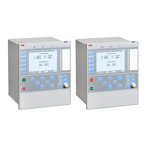
• 19" dual rack mounting kit See ordering for details about available mounting alternatives. IEC09000673.ai IEC09000673 V1 EN-US Figure 8. Flush mounted IED 222 mm 27 mm 13 mm ABB Power Grids © Copyright 2011 ABB Power Grids. All rights reserved... - Page 26 482.6 mm (19") Figure 12. Main unit and detached LHMI display 13 mm 265.9 mm (6U) 25.5 mm 258.6 mm 220 mm 265.9 mm 13 mm 224 mm 265.9 mm ABB Power Grids © Copyright 2011 ABB Power Grids. All rights reserved...
-
Page 27: Connection Diagrams
Connection diagrams for Configured products Connection diagram, REL650 1.1, (3Ph/1CB) A01 1MRK006501-HB Connection diagram, REL650 1.1, (3Ph/1CB) A05 1MRK006501-TB Connection diagram, REL650 1.1, (1Ph/1CB) A11 1MRK006501-KB ABB Power Grids © Copyright 2011 ABB Power Grids. All rights reserved... -
Page 28: Technical Data
100 V AC/ 110 V AC/ 115 V AC/ 120 V AC Voltage withstand: • Continuous 420 V rms • For 10 s 450 V rms Burden at rated voltage <0.05 VA Residual current Phase currents or residual current ABB Power Grids © Copyright 2011 ABB Power Grids. All rights reserved... - Page 29 15 A Make and carry for 0.5 s 30 A Breaking capacity when the control-circuit time constant L/R<40 ≤1 A/≤0.3 A/≤0.1 A ms, at U< 48/110/220 V DC ABB Power Grids © Copyright 2011 ABB Power Grids. All rights reserved...
- Page 30 Optical serial port, type ST for IEC 60870-5-103 Influencing factors GUID-59B01F47-1193-4243-B78C-EC6149CFA107 v12 IP15846-1 v1 Table 12. Degree of protection of flush-mounted IED Description Value Front side IP 40 Rear side, connection terminals IP 20 ABB Power Grids © Copyright 2011 ABB Power Grids. All rights reserved...
- Page 31 96 h at +85ºC Damp heat tests steady state 240 h at +40ºC IEC 60068-2-78 humidity 93% cyclic 6 cycles at +25 to +55ºC IEC 60068-2-30 humidity 93...95% ABB Power Grids © Copyright 2011 ABB Power Grids. All rights reserved...
- Page 32 IEC 60255-25 • Conducted, RF-emission (mains terminal) 0.15...0.50 MHz < 79 dB(µV) quasi peak < 66 dB(µV) average 0.5...30 MHz < 73 dB(µV) quasi peak < 60 dB(µV) average ABB Power Grids © Copyright 2011 ABB Power Grids. All rights reserved...
- Page 33 Bump test IEC 60255-21-2 Class 1 Seismic test IEC 60255-21-3 Class 2 Product safety GUID-2AA791D9-FA91-4F1F-A31D-64412575CE81 v8 Table 19. Product safety Description Reference LV directive 2006/95/EC Standard EN 60255-27 (2005) ABB Power Grids © Copyright 2011 ABB Power Grids. All rights reserved...
- Page 34 Line distance protection REL650 1MRK 506 328-BEN B Version 1.1 IEC EMC compliance GUID-9B1F0C9F-664E-41C8-ADA3-4376E096A9C9 v4 Table 20. EMC compliance Description Reference EMC directive 2004/108/EC Standard EN 50263 (2000) EN 60255-26 (2007) ABB Power Grids © Copyright 2011 ABB Power Grids. All rights reserved...
- Page 35 CVT’s and 0.5<SIR<30 Impedance zone timers (0.000-60.000) s ± 0.5% ± 10 ms Operate time 30 ms typically Reset ratio 105% typically Reset time 35 ms typically ABB Power Grids © Copyright 2011 ABB Power Grids. All rights reserved...
- Page 36 Dynamic overreach <5% at 85 degrees measured with CVT’s and 0.5<SIR<30 Timers (0.000-60.000) s ± 0.5% ± 10 ms Operate time 30 ms typically Reset ratio less than 105% ABB Power Grids © Copyright 2011 ABB Power Grids. All rights reserved...
- Page 37 Angle: at 0 degrees and 85 degrees Resistive reach (0.10–1000.00)W Timers (0.000-60.000) s ± 0.5% ± 25 ms Minimum operate current (5-30) of IBase ± 1% of I ABB Power Grids © Copyright 2011 ABB Power Grids. All rights reserved...
- Page 38 45 ms typically at 10 to 0 x I Critical impulse time 2 ms typically at 0 to 10 x I Dynamic overreach < 5% at t = 100 ms ABB Power Grids © Copyright 2011 ABB Power Grids. All rights reserved...
- Page 39 25 ms typically at 2 to 0 x I funciton Critical impulse time 10 ms typically at 0 to 2 x I Impulse margin time 15 ms typically ABB Power Grids © Copyright 2011 ABB Power Grids. All rights reserved...
- Page 40 40 ms typically at 10 to 0 x I Critical impulse time 2 ms typically at 0 to 10 x I Dynamic overreach < 5% at t = 100 ms ABB Power Grids © Copyright 2011 ABB Power Grids. All rights reserved...
- Page 41 Operate time, directional start 30 ms typically at 0,5 to 2 x I function Reset time, directional start 30 ms typically at 2 to 0,5 x I function ABB Power Grids © Copyright 2011 ABB Power Grids. All rights reserved...
- Page 42 Reset time, non-directional 120 ms typically at 1.2 to 0.8 x U residual overvoltage Operate time, directional 260 ms typically at 0.5 to 2 x I residual over current ABB Power Grids © Copyright 2011 ABB Power Grids. All rights reserved...
- Page 43 Alarm temperature (0-200)°C ± 2.0% of heat content trip Trip temperature (0-600)°C ± 2.0% of heat content trip Reset level temperature (0-600)°C ± 2.0% of heat content trip ABB Power Grids © Copyright 2011 ABB Power Grids. All rights reserved...
- Page 44 Resetting time 30 ms typically at 2 to 0 x I Critical impulse time 10 ms typically at 0 to 2 x I Impulse margin time 15 ms typically ABB Power Grids © Copyright 2011 ABB Power Grids. All rights reserved...
- Page 45 Accuracy valid for 50 Hz. At 60 Hz both accuracies are ±2.0% Accuracy valid for 50 Hz. At 60 Hz the accuracy is -50/+100% Accuracy valid for 50 Hz. At 60 Hz the accuracy is ±40% ABB Power Grids © Copyright 2011 ABB Power Grids. All rights reserved...
- Page 46 Reset time, start function 40 ms typically at 0.5 to 2 x U Critical impulse time 10 ms typically at 2 to 0 x U Impulse margin time 15 ms typically ABB Power Grids © Copyright 2011 ABB Power Grids. All rights reserved...
- Page 47 Operate voltage (0–100)% of UBase ± 0.5% of U Reset ratio <105% Pulse timer (0.050–60.000) s ± 0.5% ± 25 ms Timers (0.000–60.000) s ± 0.5% ± 25 ms ABB Power Grids © Copyright 2011 ABB Power Grids. All rights reserved...
- Page 48 (45.00 - 65.00) Hz ± 2.0 mHz Timers (0.000 - 60.000) s <130 ms Operate time, start function At 50 Hz: 100 ms typically At 60 Hz: 80 ms typically ABB Power Grids © Copyright 2011 ABB Power Grids. All rights reserved...
- Page 49 ± 0.5% ± 25 ms Time delay for energizing check (0.000-60.000) s ± 0.5% ± 25 ms Closing time for the circuit breaker (0.000-60.000) s ± 0.5% ± 25 ms ABB Power Grids © Copyright 2011 ABB Power Grids. All rights reserved...
- Page 50 CB check time before unsuccessful (0.00-6000.00) s Wait for master release (0.00-6000.00) s Wait time after close command before (0.000-60.000) s proceeding to next shot ABB Power Grids © Copyright 2011 ABB Power Grids. All rights reserved...
- Page 51 ± 0.5% ± 10 ms Delay time for current reversal (0.00-6000.00) s ± 0.5% ± 10 ms Coordination time for weak-end infeed (0.000-60.000) s ± 0.5% ± 10 ms logic ABB Power Grids © Copyright 2011 ABB Power Grids. All rights reserved...
- Page 52 ± 0.5% ± 10 ms GUID-19FB0445-FD04-4CF8-AF88-9B9BC823F052 v1 Table 64. Tripping logic SPTPTRC Function Range or value Accuracy Trip action 3-Ph, 1/3-Ph Timers (0.000-60.000) s ± 0.5% ± 10 ms ABB Power Grids © Copyright 2011 ABB Power Grids. All rights reserved...
- Page 53 Accuracy valid for 50 Hz. At 60 Hz the accuracy is <0.04. M13416-1 v4 Table 67. Event counter CNTGGIO Function Range or value Accuracy Counter value 0-10000 Max. count up speed 10 pulses/s ABB Power Grids © Copyright 2011 ABB Power Grids. All rights reserved...
- Page 54 M12700-1 v3 Table 70. Event list DRPRDRE Function Value Buffer capacity Maximum number of events in the list 1000 Resolution 1 ms Accuracy Depending on time synchronizing ABB Power Grids © Copyright 2011 ABB Power Grids. All rights reserved...
- Page 55 Upper limit for the battery terminal voltage (60-140) % of Ubat ± 1.0% of set battery voltage Reset ratio, upper limit >95 % Timers (0.000-60.000) s ± 0.5% ± 110 ms ABB Power Grids © Copyright 2011 ABB Power Grids. All rights reserved...
- Page 56 Table 80. Function for energy calculation and demand handling ETPMMTR Function Range or value Accuracy Energy metering MWh Export/Import, MVArh Input from MMXU. No extra error at steady load Export/Import ABB Power Grids © Copyright 2011 ABB Power Grids. All rights reserved...
- Page 57 ANSI Long Time Extremely Inverse A=64.07, B=0.250, P=2.0 ANSI Long Time Very Inverse A=28.55, B=0.712, P=2.0 ANSI Long Time Inverse k=(0.05-999) in steps of 0.01 A=0.086, B=0.185, P=0.02 ABB Power Grids © Copyright 2011 ABB Power Grids. All rights reserved...
- Page 58 = (0.05-999) in steps of 0.01 IEC 60255-151, class 5 + characteristic 40 ms æ ö ç × ÷ 1.35 è ø EQUATION1138-SMALL V1 EN-US I = I measured ABB Power Grids © Copyright 2011 ABB Power Grids. All rights reserved...
- Page 59 = (0.05-1.10) in steps of 0.01 unless otherwise stated × 0.055 æ ö < - ç × ÷ è ø < EQUATION1432-SMALL V1 EN-US U< = U U = U measured ABB Power Grids © Copyright 2011 ABB Power Grids. All rights reserved...
- Page 60 > EQUATION1437-SMALL V1 EN-US Type C curve: k = (0.05-1.10) in steps of 0.01 × æ ö > ç × ÷ 0.035 è ø > EQUATION1438-SMALL V1 EN-US ABB Power Grids © Copyright 2011 ABB Power Grids. All rights reserved...
-
Page 61: Ordering
Selection for position #4. Additional HMI language No second HMI language Chinese Selection for position #4. Casing Notes and Rules Rack casing, 6 U 1/2 x 19" Selection for position #5. ABB Power Grids © Copyright 2011 ABB Power Grids. All rights reserved... - Page 62 Slot position (rear view) Available slots in 1/2 case No board in slot Binary input/output module 9 BI, 3 NO Trip, 5 NO Signal, 1 CO Signal Selection for position #10. ABB Power Grids © Copyright 2011 ABB Power Grids. All rights reserved...
- Page 63 Connectivity packages and LED label template is always included for each IED. Rule: Specify additional quantity of IED Connect CD requested User documentation 1MRK 003 500-AA Quantity : ABB Power Grids © Copyright 2011 ABB Power Grids. All rights reserved...
- Page 64 Reference information M2175-3 v4 For our reference and statistics we would be pleased to be provided with the following application data: Country: End user: Station name: Voltage level: ABB Power Grids © Copyright 2011 ABB Power Grids. All rights reserved...
- Page 65 Communication protocol manual, IEC 60870-5-103 1MRK 511 243-UEN Point list manual, DNP3 1MRK 511 244-UEN Engineering manual 1MRK 511 245-UEN Operation manual 1MRK 500 093-UEN Installation manual 1MRK 514 014-UEN ABB Power Grids © Copyright 2011 ABB Power Grids. All rights reserved...
- Page 67 ABB Power Grids Sweden AB Grid Automation Products SE-721 59 Västerås, Sweden Phone +46 (0) 10 738 00 00 Scan this QR code to visit our website https://www.abb.com/protection-control © Copyright 2011 ABB Power Grids. All rights reserved.