
Related Manuals for Scotsman NWH Series


Summary of Contents for Scotsman NWH Series
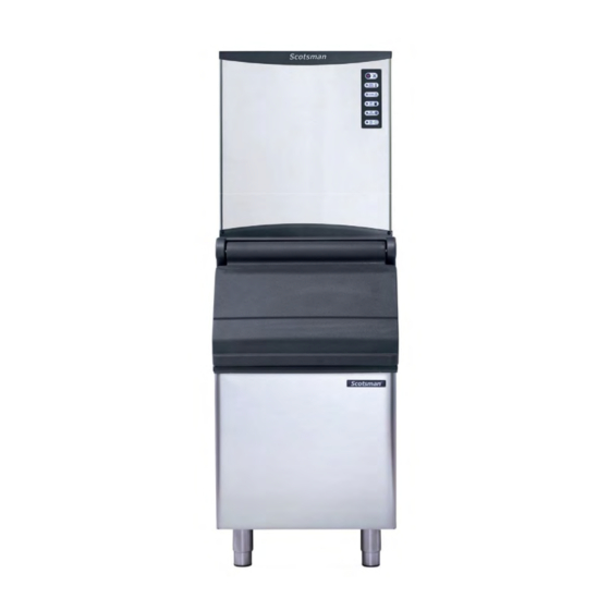
- Page 1 Full Cube – 12 gr Half Cube – 6 gr NW(H) SERIES DICE & HALFDICE CUBERS TECHNICAL SERVICE TRAINING Welcome to another Scotsman Technical Service Presentation that cover all NW models REV. 03/2018...
- Page 2 NW(H) 308 Max. Ice production = 147 Kg/24h* Max. Storage Bin Capacity - NB 193 = 129 Kg * 21/10°C = Air & Water Inlet Temperature...
- Page 3 NW(H) 508 Max. Ice production = 215 Kg/24h* Max. Storage Bin Capacity - NB 193 = 129 Kg * 21/10°C = Air & Water Inlet Temperature...
- Page 4 NW(H) 458 Max. Ice production = 200 Kg/24h* Max. Storage Bin Capacity NB 393 = 178 Kg NB 530 = 243 Kg * 21/10°C = Air & Water Inlet Temperature...
- Page 5 NW(H) 608 Max. Ice production = 280 Kg/24h* Max. Storage Bin Capacity NB 393 = 178 Kg NB 530 = 243 Kg * 21/10°C = Air & Water Inlet Temperature...
- Page 6 NW(H) 1008 Max. Ice production = 456 Kg/24h* Max. Storage Bin Capacity NB 530 = 243 Kg NB 948 = 406 Kg * 21/10°C = Air & Water Inlet Temperature...
- Page 7 TOPICS On the next slides are shown the following steps by steps procedures: • UNPACKING • INSTALLATION • START UP AND OPERATIONAL CHECKS • OPERATING PRINCIPLES and COMPONENTS • MAINTENANCE • SERVICE ANALYSIS...
- Page 8 UNPACKING...
- Page 9 The machines are supplied in a carton box secured by two plastic strips to a wooden base. Check first the outside conditions of carton box and wooden base then cut the two plastic strips, remove the tape and then the carton box.
- Page 10 Visually inspect the exterior of the machine, then remove the front and both side panels, unscrews the two sides screws that secure the machine to the wooden base...
- Page 11 Remove the water inlet and outlet hoses, the red adhesive tapes and the air baffle deflector NW308 and 508 are equipped with a top grid...
- Page 12 Remove the front plastic deflector and take out the second red adhesive tape securing the ice thickness sensor...
- Page 13 The Modular NW machines require for the installation the use of a companion storage bin to store the ice produced. Storage bins required: • NB193 with NW 308 - NW 508 • NB 393/530 with NW 458 - NW 608 •...
- Page 14 Unpack the storage bin and visually inspect the exterior then remove from the inside the carton box containing the legs as well as the drain hose and the plastic scoop...
-
Page 15: Installation
INSTALLATION... - Page 16 Install the four legs and their adjusting leveling nuts on the bottom base as well as the water drain tube...
- Page 17 ... install on top of the same the ice machine and secure it with the two sides screws.
- Page 18 NW 458-608-1008 On air cooled version unloose a little bit the screws securing the air cooled condenser to the unit frame, then install the metal plate (air baffle) on the back side of the machine...
- Page 19 NW 458-608-1008 The installation of the MINIMUM COLD AIR DISTANCE metal plate (air separator) grants also a minimum distance between the back side of the machine and the HOT AIR HOT AIR wall so to assure a TOP VIEW correct and adequate ventilation minimize the possible recycling of hot air through the rear panel...
- Page 20 NW 458-608-1008 Min. space 15 cm Adequate space must left for proper water and electrical connections on the rear side of the machine and a minimum clearance of 15 cm on right side for best routing air.
- Page 21 NW 308-508 ... install the grids on top panel...
- Page 22 AIR CIRCULATION NW 308-508 FAN MOTOR CONDENSER COLD AIR HOT AIR COMPRESSOR DISCHARGE ICE CHUTE EVAPORATOR OPENING...
- Page 23 NW 308-508 SPACE SAVING VERSION Hot air exit from the top. No need of side clearance from walls or other equimpent. Natural direction of hot air flow, from bottom to top.
- Page 24 Check the data plate of the machine located on the rear panel for correct voltage as well as for the proper wiring/fuse size. Remember that all machines require a solid earth wire.
- Page 25 Check for the correct water and ambient conditions that should be: • Min. ambient temperature 10ºC (50F) • Max. ambient temperature 40ºC (100F) • Min. water temperature 5ºC (40F) • Max. water temperature 35ºC (90F) • Min. water pressure 1 bar (14 PSI) •...
- Page 26 Level the unit on both directions front to rear and right to left side using the adjustable legs of the storage...
- Page 27 Install, on the cable supply with the machine, an adequate electrical plug according to the local standards and regulations. Maximum voltage variation should be ±10%. Machine must be individually fuse protected.
- Page 28 Connect the water inlet 3/4” male threat of the water inlet fitting to the water supply line by means of the rubber hose provided with machine. Connect also the 20 mm O.D. fitting of the water drain with the flexible hose supply with the machine with its proper clamp.
-
Page 29: Typical Installation
TYPICAL INSTALLATION AIR COOLED POWER HAND DISCONNECT SWITCH WATER INLET WATER VALVE WATER FILTER WATER DRAIN WATER DRAIN... -
Page 30: Water Cooled
TYPICAL INSTALLATION WATER COOLED POWER HAND DISCONNECT SWITCH WATER INLET WATER VALVE WATER FILTER WATER DRAIN WATER DRAIN... - Page 31 START UP OPERATIONAL CHECKS...
- Page 32 Open the water tap/valve and switch ON the power on the electrical supply line.
- Page 33 The machine enters in the first part of Start-up (Automatic clean) cycle that is used to rinse the water reservoir with the LED of ICE MAKING and BIN FULL blinking for 2 minutes.
- Page 34 During these 2 minutes the components of water system work to purge and refill the water reservoir Water pump : 60” Water pump + water inlet valve + drain valve : 20” Water pump + water drain valve: 40” (20”) Water Inlet Valve Water Drain Valve Water Pump...
- Page 35 Once completed the first part of the Start-up cycle the machine enters in the pressure balance mode that takes 40 seconds, with the slow blinking of the Green LED second of making...
- Page 36 During the pressure balance mode the refrigerant pressure is checked with the following components in operation: Hot gas valve: 35” Hot gas valve + compressor: last 5” END (40”) Hot Gas Valve Compressor (5 ”) START...
- Page 37 Model NW 1008 only has a crankcase heater in the compressor. When the main power to the machine is switched ON, there is a time delay of 90 minutes during which only the compressor heater is energized with Green ICE Making LED Blinking slowly.
- Page 38 This delay can also be by- passed pressing the switch located on the rear panel of the machine. Once the delay is elapsed the machine enters in Start-up cycle doing water reservoir rinse and pressure balance...
- Page 39 After the start up cycle the machine enters directly into the FREEZING CYCLE with the following components energized: • Water Inlet valve • Compressor • Fan motor The LED energized are: • ICE MAKING (steady) • ON/OFF (steady)
- Page 40 • Water is coming into the water through the Water Inlet Solenoid Valve till the water reservoir is filled up to the maximum level controlled by a water level sensor. • The Water Pump starts up 40 seconds later. • After few minutes (3-5) from the start up of the freezing cycle, the Water Inlet Solenoid Valve is activated again for few seconds to...
- Page 41 The fan motor works in continuos mode for 3 minutes at the beginning of the freezing cycle In the meantime the condenser sensor starts to transmit the current to the PC Board keep in operation the Fan Motor in ON- mode or continuously •...
- Page 42 The machine remains in the freezing cycle with ice become thicker, till the metal plate of the ice thickness sensor are covered by the water cascading down through the front surface of the ice plate.
- Page 43 When the power is transmitted back continuously to the PC Board through the metal plate of the ice thickness sensor for more than 6 seconds, machine enters in the harvest cycle . POWER , OPERATION and HARVEST lights are on steady...
- Page 44 During the harvest cycle the components in operation are: • Hot Gas Valve • Water Drain valve...
- Page 45 During the harvest cycle the components in operation are: • Water pump (according with DIP SWITCH n. 6 – 7 ) • Compressor...
- Page 46 When the Harvest Cycle starts , Drain Valve and Water Pumps purge out old water for a pre-set time according with Dip-SWITCH n.6-7. After 20” of operation of Water Drain Valve also the Water inlet Valve will be activated for 10” in order to have a short flush of fresh water into the water sump while the Water Pump and Drain...
- Page 47 While the ice plate is falling down, it moves the front plastic cover out from the evaporator causing the activation of the magnetic switch to restart a new freezing cycle.
- Page 48 When the last ice plate discharged from the evaporator, the plastic deflector cover keeps in open position for 30” . The ice full sensor transmit the signal to the PC Board, all the components stop working, and the BIN FULL light is on steady.
- Page 49 PC BOARD...
-
Page 50: Monitor Panel
MONITOR PANEL It is located on the upper right side behind the front panel the monitor panel It is composed by two push button ( MODE and CLEAN ) and seven indicator/alarm lights... - Page 51 MONITOR PANEL MODE PUSH BUTTON HI PRESSURE ALARM INDICATOR LIGHT ALARM INDICATOR LIGHT CLEAN PUSH BIN FULL INDICATOR BUTTON LIGHT CLEAN INDICATOR OPERATION LIGHT INDICATOR LIGHT HARVEST POWER INDICATOR INDICATOR LIGHT LIGHT...
-
Page 52: Alarm Conditions
ALARM CONDITIONS Red LED Both the last two are ON STEADY : CONDENSER SENSOR OUT OF ORDER... - Page 53 ALARM CONDITIONS Red LED Both the last two are BLINKING SLOW: WATER ERROR Water level inside the water sump too low after 3 or 6 minutes from the activation of the Water Inlet Valve according with setting of DIP SWITCH n.4...
- Page 54 ALARM CONDITIONS Both the last two Red LED are BLINKING FAST: RESET MODE Charging water through the Water Inlet Solenoid Valve after the tripping OFF on WATER ERROR NOTE = to assure a proper operation of the machine the water must have a minimum electric conductivity of 20µS...
- Page 55 ALARM CONDITIONS Red Led is BLINKING The Fourth SLOW: TOO HI CONDENSING TEMPERATURE The condenser sensor detected a > 70°C temperature Reset Mode: For the first two times, machine will automatic reset , it will stops when the alarm occours the third time.
- Page 56 ALARM CONDITIONS The Fourth Red LED is ON steady: 3 TIMES TOO LONG HARVEST CYCLE TIME (according with setting of DIP SWITCH n.3) Reset Mode: Press MODE button to reset and go to start up cycle...
- Page 57 ALARM CONDITIONS The Fifth Red LED is ON STEADY: TOO HI DISCHARGE PRESSURE (MORE THAN 33 BAR / 460 PSI ) Reset Mode: Press MODE button to reset and go to start up cycle...
- Page 58 ALARM CONDITIONS Both the third YELLOW LED fourth Red LED are blinking fast : ICE THICKNESS SENSOR FAULT When machine starts, if PC Board detects the Ice Thickness ON machine will stop Reset Mode: Press MODE button to reset and go to start up cycle...
- Page 59 ALARM CONDITIONS Whenever the machine remains in the Freezing Cycle for the Maximum time (30 or 40 minutes), the PC Board moves the unit directly into the Harvest Cycle.
- Page 60 ALARM CONDITIONS PC Board is also checking the maximum time of the freezing cycle that changes according to the operation of the fan motor during the freezing cycle (room temperature): • Fan motor in ON-OFF mode: Max. freezing cycle length equal to 30’ •...
- Page 61 PC BOARD SETTING MODE BUTTON FUNCTION • To restart the machine is necessary press the MODE button. • When machine is working, press MODE button to go to next process as follow: Start Automatic Clean Pressure Balance Freezing Harvest Bin Full...
- Page 62 PC BOARD SETTING Default Factory setting : All Dip-Switches OFF...
- Page 63 PC BOARD SETTING DIP-SWITCH n. 1 OFF = Used on NW Series ON = Factory use only...
- Page 64 PC BOARD SETTING DIP-SWITCH n. 2 OFF = No start-up time delay ON = 90’ start-up time delay (Used on NW 1008 only)
- Page 65 PC BOARD SETTING DIP-SWITCH n. 3 OFF = 3’ and 30” Max. Harvest Time ON = 6’ max. Max. Harvest Time...
- Page 66 PC BOARD SETTING DIP-SWITCH n. 4 OFF = 3’ and 30” Water fill time ON = 6’ water fill time...
- Page 67 PC BOARD SETTING DIP-SWITCH n. 5 OFF = Fill water in first 4’ in freezing cycle ON = Fill water in first 10’ in freezing cycle...
- Page 68 PC BOARD SETTING DIP-SWITCH n. 6 - 7 Purge water control DIP n. 6 DIP n. 7 WATER PUMP Works for 30 seconds Works for 6 seconds and 30 seconds every six harvest cycles Works for 30 seconds every three harvest cycles Works for 30 seconds every six cycles...
- Page 69 PC BOARD SETTING DIP-SWITCH n. 8 FACTORY USE ONLY DIP-SWITCH n. 9 OFF = Machine will stop after clean procedure, need to press clean button to restart ON = Machine will restart automatically after clean procedure...
- Page 70 PC BOARD PUSH BUTTON PC Board and display are both equipped with MODE and CLEAN push button having the same function...
- Page 71 OPERATING PRINCIPLES COMPONENTS...
- Page 72 OPERATING PRINCIPLES - FREEZE Evaporator Air cooled valve condenser Compressor...
- Page 73 OPERATING PRINCIPLES - HARVEST Evaporator Air cooled valve condenser Compressor...
- Page 74 WATER SYSTEM – FREEZING CYCLE 1° PART – 40”...
- Page 75 WATER SYSTEM – FREEZING CYCLE 2° PART...
- Page 76 WATER SYSTEM – HARVEST CYCLE First 20”...
- Page 77 WATER SYSTEM – HARVEST CYCLE From 20” up to 30”...
- Page 78 WATER SYSTEM – HARVEST From 30” up to the end of harvest cycle...
- Page 79 COMPONENTS - REFRIGERANT SYSTEM The components of the refrigerant system of the NW series are: • COMPRESSOR...
- Page 80 COMPONENTS - REFRIGERANT SYSTEM • CONDENSER...
- Page 81 COMPONENTS - REFRIGERANT SYSTEM • EVAPORATOR...
- Page 82 COMPONENTS - REFRIGERANT SYSTEM • TXV VALVE...
- Page 83 COMPONENTS - REFRIGERANT SYSTEM • DRIER...
- Page 84 COMPONENTS - REFRIGERANT SYSTEM • HOT GAS VALVE...
- Page 85 COMPONENTS - REFRIGERANT SYSTEM • HIGH PRESSURE CTRL...
- Page 86 COMPONENTS – WATER SYSTEM The components of the water system of the NW series are: • WATER INLET VALVE...
- Page 87 COMPONENTS – WATER SYSTEM • WATER SUMP...
- Page 88 • WATER PUMP...
- Page 89 COMPONENTS – WATER SYSTEM • WATER DISTRIBUTOR TUBE...
- Page 90 COMPONENTS – WATER SYSTEM • WATER FLOW ADJUSTERS...
- Page 91 COMPONENTS – WATER SYSTEM • WATER DRAIN VALVE...
- Page 92 COMPONENTS - ELECTRONIC CONTROLS The components of the Electronic System of the NW Series Models are : • PC BOARD...
- Page 93 COMPONENTS - ELECTRONIC CONTROLS • ICE THICKNESS SENSOR...
- Page 94 COMPONENTS - ELECTRONIC CONTROLS • CONDENSER SENSOR...
- Page 95 COMPONENTS - ELECTRONIC CONTROLS • MAGNET • MAGNETIC SWITCH...
- Page 96 COMPONENTS - ELECTRONIC CONTROLS • WATER LEVEL SENSOR...
- Page 97 COMPONENTS - ELECTRONIC CONTROLS • WATER LEVEL SENSOR NW 308-508...
-
Page 98: Maintenance
MAINTENANCE The most important program on the maintenance of the cubers machines is the cleaning/sanitizing to be done on regular base as detailed here below regular base as detailed here below: • Sanitizing: Every month • Cleaning: Every six On next slides will be shown the procedure for sanitizing and cleaning. -
Page 99: Tools Required
TOOLS REQUIRED • Medium Phillips Screwdriver • Medium Flat Screwdriver • Pair of safety gloves • Bucket • Different types of brush • Approved Cleaner/Sanitiser... - Page 100 Wait till the end of the defrost/harvest cycle; then switch off the machine from the main switch and close the water tap CLOSED...
- Page 101 MAINTENANCE Scoop out all ice cubes stored into the bin so to prevent its contamination then...
- Page 102 NW 308-508 NW 458-608-1008...
- Page 103 Be assured water sump is empty by water. In case dump the same by removing drain plastic plug...
- Page 104 ... And the plastic deflector...
- Page 105 Push the ice thickness sensor external plastic arms and take it off from its housing...
- Page 106 Disconnect the water inlet hose from distributor tube...
- Page 107 Open up the water distribution tube for cleaning...
- Page 108 Once properly cleaned re-assembly the Water Distributor Tubes then re-fit it again on the upper side of the evaporator paying attention to match the plastic pin with the hole.
- Page 109 Unscrew water pump bracket screws and remove it from the reservoir...
- Page 110 Disconnect the water pump from its power spade connectors...
- Page 111 Remove water pumps from the reservoir and disconnect the water discharge hose...
- Page 112 Unscrew the two thumb screws then withdraw reservoir from its seat...
- Page 113 NW 308-508 Unscrew water pump bracket screws and remove it from the reservoir...
- Page 114 NW 308-508 Unloose water pump bracket screws and remove spade connectors...
- Page 115 NW 308-508 Slip to the left side the water pump bracket thus to release the same from the water reservoir and lift up the water pump...
- Page 116 NW 308-508 disconnect the water water discharge hose...
- Page 117 NW 308-508 Push the water level sensor arms IN and remove the same from its seat...
- Page 118 NW 308-508 Hang on water reservoir left holding bracket and withdraw reservoir from its seat...
- Page 119 Prepare the cleaning solution by diluting in a plastic bucket two liters of lukewarm water (max 40ºC) with 200 ml of SCOTSMAN Ice Machine Cleaner.
- Page 120 Clean evaporator plastic cover by cleaning solution then rinse it by fresh water...
- Page 121 Clean water distribution tubes and water reservoir by cleaning solution then rinse it by fresh water...
- Page 122 All above step (cleaning) shall also be made by antibacterial solution (finally rinsed by fresh water) then, carefully reinstall all cleaned removed parts Once completed cleaning procedure on removed parts reinstall the same accordingly...
- Page 123 Switch ON the machine from the main switch and OPEN the water tap OPEN...
- Page 124 Push CLEAN BUTTON 2-3 seconds...
- Page 125 The machine enters in the Cleaning/Sanitize cycle with the red CLEAN LED light on MONITOR PANEL blinking fast whole procedure...
- Page 126 In the first 30 seconds of clean procedure the machine purge water from the sump, then pour: NW 308: 180 ml NW 506: 200 ml NW 458-608: 350 ml NW 1008: 350 ml of SCOTSMAN cleaner inside water sump while…...
- Page 127 ……the water inlet valve will be energized till the fill up of the water sump . The water pump starts to operate...
- Page 128 With the system in Cleaning mode the water pump is the only component in operation to circulate the cleaning solution in the entire water system.
- Page 129 After 10 minutes from the start of the cleaning cycle machine will purge automatically the Cleaner solution and refill up the water sump, then goes into automatic rinsing mode.
- Page 130 RINSING MODE consists of: • Energize water pump for 30” • Energize water drain valve and water pump for 30” • Energize water inlet valve till the fill up of the water sump • The above sequence is repeated 10 times to be sure to have removed any possible trace of Ice Machine Cleaner...
- Page 131 At the end of 10th rinsing cycle, the machine restart according with the setting of DIP-SWITCH n.9 OFF = Machine will stop clean procedure with slow blinking of Red CLEAN light Push CLEAN button to restart in freezing cycle ON = Machine will restart automatically with a new freezing cycle...
- Page 132 Repeat same procedure pouring approx. 5 ml of Sanitizer (Amuchina) directly into the water reservoir...
- Page 133 Meanwhile the unit is running the rinsing cycle , mix in a clean bucket some fresh water with 1% of sanitizer product (Amuchina)
- Page 134 Fill up with the mixed solution a spray bottle, then spray the same to all bin internal wall/area and wipe with a proper brush the SS deflector as well as the internal surface of the plastic door and the internal area of the bin...
- Page 135 REMEMBER: The interior liner of the bin is in contact with a food product, ice, and needs to be cleaned and sanitized regularly (one a week) to prevent accumulation of bacteria. Once a week sanitize it with a commercial food grade sanitizers complying with the manufacturer dilution instruction...
- Page 136 Install back the front panel and switch ON the machine. Check next batch, if it s cloudy, white and have an acid taste, melt them immediately by pouring on them some warm water. This to prevent that somebody can use it...
- Page 137 Monthly check and clean rear air filter...
-
Page 138: Service Analysis
SERVICE ANALYSIS... - Page 139 SERVICE ANALYSIS This is a Scotsman Dice Cube. It must be clear, solid with a bottom rim of about 3-4 mm 3-4 mm and a small depression of 9- 10 mm.
- Page 140 SERVICE ANALYSIS The Ice Thickness Sensor must be adjusted so to have a clearance of approximately 3-5 mm 3-5 mm between the bottom of the two metal plates and the front of the evaporator cells.
- Page 141 SERVICE ANALYSIS This ice cube is clear, solid but it has a deep depression on its bottom rim due to a too short freezing cycle.
- Page 142 SERVICE ANALYSIS It is necessary to extend the length of the freezing cycle by adjusting the clearance between the ice thickness sensor and the front of the evaporator turning the adjusting screw clockwise.
- Page 143 SERVICE ANALYSIS This ice cube is clear, solid but it is oversized due to a too long freezing cycle.
- Page 144 SERVICE ANALYSIS It is necessary to reduce the length of the freezing cycle by adjusting the clearance between the ice thickness sensor and the front of the evaporator turning the adjusting screw counterclockwise.
- Page 145 SERVICE ANALYSIS This is a typical ice cube clear on its upper left side and white and corroded on its bottom right side. The reason is that the water doesn’t reach in correctly the inside of some of the evaporator molds.
- Page 146 SERVICE ANALYSIS Should be due to clogged spray jets...
- Page 147 SERVICE ANALYSIS To solve this trouble check and clean spray bar as shown on the previous Cleaning Procedures...
- Page 148 SERVICE ANALYSIS These ice cubes are both clear, solid but some are oversized and some other are undersized. If so the possible reasons could be: • TXV not working properly • Low refrigerant charge...
- Page 149 SERVICE ANALYSIS Looking the evaporator, after 15-20 minutes in the freeze, the ice is probably…..
- Page 150 SERVICE ANALYSIS thick on the bottom portion (inlet of refrigerant) and thin on the upper one (outlet) due to the lack of exchange of heat between refrigerant - already in vapor state - and cascading water.
- Page 151 SERVICE ANALYSIS Check the operating pressures of the refrigerant system connecting the gauges on hi and low service valve. The operating pressures at the end of the freezing cycle with unit at 21ºC ambient and 10°c water inlet should be: Suction Suction Hi pressure...
- Page 152 SERVICE ANALYSIS If the pressures are not the right ones, it will be necessary to replace the TXV valve...
- Page 153 SERVICE ANALYSIS One more possible reason could be the serpentine no longer proper welded on the back side of the evaporator.
- Page 154 SERVICE ANALYSIS If so, ice is produced in spots, according to the different transmission of heat between the refrigerant in circulation on the serpentine and evaporator surface.