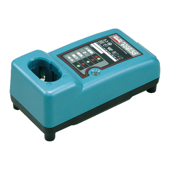
Makita DC1804 Technical Information
Hide thumbs
Also See for DC1804:
- Parts list (1 page) ,
- Manual (32 pages) ,
- Instruction manual (17 pages)
Advertisement
Quick Links
T
ECHNICAL INFORMATION
Models No.
Description
C
ONCEPTION AND MAIN APPLICATIONS
Multi voltage charger DC1804 is the renewed model of DC1803.
Its features and benefits are
(1) Approx. 10-20 minutes shorter charging time in comparing
with DC1801.
(2) Maintenance (trickle) charging system keeps the full charged
condition for 24 hours, even if the battery is left in this charger
after finishing of charging process.
(3) Downsized ; The dimensions have been reduced to those of DC1413.
S
pecification
Voltage (V)
110 - 120
120
220
220 - 240
230 - 240
Output voltage DC : V
Output current : A
for 1.3Ah Ni-Cd. battery
for 2.0Ah Ni-Cd. battery
Charging
for 2.2Ah Ni-MH. battery
time : min.
for 2.6Ah Ni-MH. battery
for 3.0Ah Ni-MH. battery
Protection against
electric shock
Cord length : m (ft )
Net weight
< Note > The above figures about charging time may differ from condition to condition on batteries' temperature
DC1804
Charger
Current (A)
Cycle (Hz)
50 / 60
50 / 60
50 / 60
50 / 60
50 / 60
110V - 120V
220V - 240V
or room temperature.
H
Continuous Rating (W)
Input
75
75
75
75
75
7.2
9.6
Approx. 30
Approx. 45
Approx. 50
Approx. 60
Approx. 70
grounding (earthing)
double insulation
2.0 (6.6)
0.39 (0.86)
W
L
Dimensions : mm ( " )
Length ( L )
Width ( W )
Height ( H )
Max. Output(W)
Output
12
14.4
2.6
PRODUCT
P 1 / 3
193 (7-5/8)
92 (3-5/8)
78 (3-1/16)
18
Advertisement

Related Manuals for Makita DC1804


Summary of Contents for Makita DC1804
- Page 1 DC1804 Description Charger ONCEPTION AND MAIN APPLICATIONS Multi voltage charger DC1804 is the renewed model of DC1803. Its features and benefits are (1) Approx. 10-20 minutes shorter charging time in comparing with DC1801. (2) Maintenance (trickle) charging system keeps the full charged condition for 24 hours, even if the battery is left in this charger after finishing of charging process.
- Page 2 P 2 / 3 epair < 1 > The circuit board cannot be repaired, because the circuit itself is molded on the board . It has to be replaced entirely with new one. < 2 > In case of damaged varistor or fuse, they can be repaired according to the following procedure without replacing the circuit board.
- Page 3 P 3 / 3 epair (3) Replacing damaged varistor a. Varistor is assembled on circuit board with solder. Remove it from circuit board with soldering iron. Varistor Circuit board Fig.2 When removing varistor, melt this part with soldering iron and remove varistor. b.