Advertisement
Quick Links
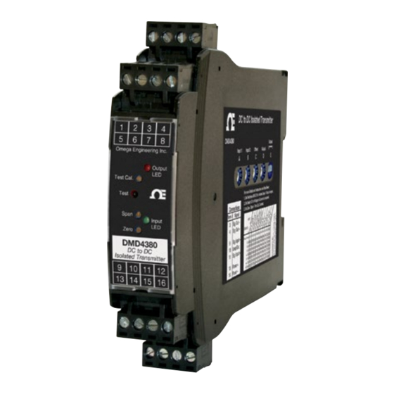
DMD4380
DMD4380-DC
DC-DC Isolated Transmitter
M-5001/0219
Model
Power
DMD4380
85-265 VAC, 50/60 Hz or 60-300 VDC
DMD4380-DC
9-30 VDC or 10-32 VAC
Description
The DMD4380 is a field-rangeable signal isolator/transmitter/con-
verter. It accepts a DC voltage or current input and provides an
optically isolated DC voltage or current output that is linearly related
to the input. Full 3-way isolation (input, output, power) makes this
module useful for ground loop elimination, signal conversion and
isolation, common mode signal rejection, or noise pickup reduction.
Standard on the DMD4380 is a 15 VDC loop excitation supply for the
input and a 20 VDC loop excitation supply for the output. These power
supplies can be selectively wired to power passive mA devices.
A green input LED and a red output LED vary in intensity with changes
in the process input and output signals. These provide a quick visual
picture of your process loop at all times.
An output test button provides a fixed output (independent of the
input) when held depressed. The test output level is potentiometer
adjustable from 0 to 100% of output span.
The I/O LEDS and the output test button greatly aid in saving time
during initial startup and/or troubleshooting.
DC Input Ranges
Field selectable ranges and offsets via switch settings
Voltage:
0-10 mVDC to 0-130 VDC
Bipolar voltage:
±5 mVDC
to ±65 VDC
Current:
0-200 µADC to 0-50 mADC
Input offset:
±100% in 15% increments
Input Impedance (Voltage)
Voltage:
1 MΩ minimum
50 Ω typical
Current:
Voltage burden:
1 VDC at 20 mA current input
Common Mode Rejection
100 dB minimum
Input Loop Power Supply
15 VDC ±10%, regulated, 25 mADC
May be selectively wired for sinking or sourcing mA input
LoopTracker
Variable brightness LEDs indicate I/O loop level and status
DC Output Ranges
Field selectable ranges and offsets via switch settings
Voltage (10 mA max):
0-1 VDC
to 0-10 VDC
Bipolar voltage:
±5 VDC
or ±10 VDC
Current:
0-2 mADC to 0-20 mADC, 4-20 mADC
20 V compliance, 1000 Ω at 20 mA
Output Calibration
Multi-turn zero and span potentiometers
±15% of span adjustment range typical
Output Loop Power Supply
20 VDC nominal, regulated, 25 mADC, <10 mVRMS max. ripple
May be selectively wired for sinking or sourcing mA output
Output Test/Override
Front button sets output to test level when pressed or via external
contact closure
Potentiometer adjustable 0-100% of span
Output Ripple and Noise
Less than 10 mVRMS ripple and noise
Linearity
Better than ±0.1% of span
Ambient Temperature Range and Stability
–10°C to +60°C operating ambient
Better than ±0.02% of span per °C stability
Response Time
70 milliseconds typical
DF option: 1 millisecond typ. (output noise will exceed specifications)
Isolation
1200 VRMS minimum
Full isolation: power to input, power to output, input to output
Housing and Connectors
IP 40, requires installation in panel or enclosure
For use in Pollution Degree 2 Environment
Mount vertically to a 35 mm DIN rail
Four 4-terminal removable connectors, 14 AWG max wire size
Power
85-265 VAC, 50/60 Hz or 60-300 VDC, 2 W maximum
D versions: 9-30 VDC or 10-32 VAC 50/60 Hz, 2 W maximum
Voltage Output
Switch E set to "V"
Current Sourcing Output
Switch E set to "I"
Current Sinking Output
Loop
switch E set to "I"
Power
Source
External Contact
for Test Function
Variable Brightness Output Indicator
Output Test Level Adjustment
Push to Test Output
Output Span Calibration
Variable Brightness Input Indicator
Output Zero Calibration
Voltage Input
Current Sinking Input
Loop
Power
Source
Current Sourcing Input
To maintain full isolation avoid
combining power supplies in
common with input, output, or
unit power.
Cu 60/75°C
13 Power AC or DC +
conductors
14
Earth Ground
14 AWG
max.
16 Power AC or DC –
User's Guide
Voltage
Device
–
+
1
2
3
4
mA
Device
R
i
–
+20V
1
2
3
4
Shop online at
4-20 mA
Device
R
+
i
+
–
–
–
+
1
2
3
4
e-mail: info@omega.com
For latest product manuals:
5
6
7
8
www.omegamanual.info
Omega Engineering Inc.
Output
LED
Test Cal.
Test
Span
Input
LED
Zero
DMD4380
DC to DC
Isolated Transmitter
9
10
11
12
–
+
Voltage
Xmtr
9
10
11
12
–
–
+
Do not connect
+
–
+
anything to
R
i
unused terminals
mA
Xmtr
9
10
11
12
Wire terminal torque
0.5 to 0.6 Nm or
+15V
–
4.4 to 5.3 in-lbs
R
i
mA
Xmtr
13
14
15
16
omega.com
MADE IN
Lifetime
TM
Pb
Lead
Free
WARNING: This product can expose you to chemicals includ-
ing nickel, which are known to the State of California to cause
cancer or birth defects or other reproductive harm. For more
information go to www.P65Warnings.ca.gov
1 2 3 4
Output
5 6 7 8
Remote Test
Input
9 1 0 1 1 1 2
Power
1 3 1 4 1 5 1 6
Advertisement

Related Manuals for Omega DMD4380


Summary of Contents for Omega DMD4380
- Page 1 Standard on the DMD4380 is a 15 VDC loop excitation supply for the input and a 20 VDC loop excitation supply for the output. These power supplies can be selectively wired to power passive mA devices.
- Page 2 2. Clip lower mount to bottom edge of DIN rail. tion, check switch settings and wiring polarity. The DMD4380 accepts a DC voltage or current input and provides an 3. Push front of module upward until upper mount snaps into place.
- Page 3 DMD4380 Series DC-DC Isolated Transmitter Output 0-1 V 0-2 V 0-4 V 1-5 V 0-5 V 0-8 V 2-10 V 0-10 V ±5 V ±10 V 0-2 mA 0-4 mA 0-8 mA 2-10 mA 0-10 mA 0-16 mA 4-20 mA 0-20 mA...
- Page 4 Department will issue an Authorized Return (AR) number immediately upon phone or written request. Upon examination by OMEGA, if the unit is found to be defective, it will be repaired or replaced at no charge. OMEGA’s WARRANTY does not apply to defects resulting from any action of the purchaser, including but not limited to mishandling, improper interfacing, operation outside of design limits, improper repair, or unauthorized modification.