Table of Contents
Advertisement
Advertisement
Table of Contents

Related Manuals for DirecTV Advanced Installation Meter 2

Summary of Contents for DirecTV Advanced Installation Meter 2
- Page 1 Advanced Installation Meter 2 Operation Manual innovative technology to keep you a step ahead Copyright © 2017 Trilithic, Inc. All Rights Reserved - 122117-REV1 Specifications are subject to change without notice. Please contact your sales representative for further information.
- Page 2 Putting Innovation Within Reach Product innovation at Trilithic has always been characterized by one thing: it’s practical. It makes life easier for customers. It’s the natural result of listening to them. That philosophy has been the driving force behind the company’s growth from its beginnings as a two-man engineering team in 1986 to its current position as a global manufacturer with more than 130 employees.
-
Page 3: Table Of Contents
Table of Contents Chapter 1 ......................7 General Information ........................7 Where to Get Technical Support ....................7 Warranty ..........................8 Return Policy ..........................8 How this Manual is Organized ....................9 Conventions Used in this Manual..................11 Precautions .......................... 11 Chapter 2 ......................13 Introduction ..........................13 What is the AIM? ........................13 Overview .........................13... - Page 4 Chapter 4 ......................27 Setting Up the Meter .......................27 Overview ..........................27 Entering Registration Information..................28 Setting up the Wi-Fi Connection ..................30 Setting up the Bluetooth Connection..................32 Setting up the Ethernet Connection ..................35 IP Settings ........................36 IP Address ........................37 Gateway, Netmask, and DNS Addresses ...............37 Changing the Volume Settings .....................38 Changing the Display Contrast or Brightness ..............39 Changing the Time and Date Settings .................40...
- Page 5 Chapter 7 ......................61 Performing EIV.........................61 Overview ..........................61 Chapter 8 ......................67 Performing Other Network Tests ...................67 Overview ..........................67 Using Guided Mode ......................68 Performing EIV Plus ......................73 Performing a Satellite Tune Test ..................78 Performing a Transponder Survey ..................81 Performing a Cable Resistance Test ..................85 Performing an In-Line Test ....................87 Performing a SWiM LF Power Test ..................89 Performing a SWiM Channel Assignments Test ..............90...
- Page 6 THIS PAGE LEFT INTENTIONALLY BLANK AIM 2 Operation Manual Page 6...
-
Page 7: Chapter 1
• Go to the DIRECTV Satellite Installer website or other websites provided by DIRECTV. DIRECTV websites contain product specifications and information, tips, release information, marketing information, Frequently Asked Questions (FAQs), bulletins and other technical information. -
Page 8: Warranty
Warranty Trilithic, Inc. warrants that each part of this product will be free from defects in materials and workmanship, under normal use, operating conditions and service, for a period of fifteen (15) months from date of shipment. The obligation of Trilithic, Inc. under this warranty shall be limited, at the sole option of Trilithic, Inc., to replacing the product or repairing any defective part. -
Page 9: How This Manual Is Organized
How this Manual is Organized This manual is divided into the following chapters: • Chapter 1: General Information provides Trilithic contact information and describes how this operation manual is structured. • Chapter 2: Introduction introduces what the AIM is and what it does. This chapter discusses the practical application, connections and controls of the AIM. - Page 10 • Chapter 9: Managing Records describes the steps needed to to view records, delete records, and transfer records to or from the AIM using a USB flash drive. • Chapter 10: Updating the Meter describes the steps needed for updating the meter’s firmware.
-
Page 11: Conventions Used In This Manual
Conventions Used in this Manual This manual has several standardized conventions for presenting information: • Connections, menus, menu options, and user-entered text and commands appear in bold. • Section names, web, and e-mail addresses appear in italics. A NOTE is information that will be of assistance to you related to the current step or procedure. - Page 12 THIS PAGE LEFT INTENTIONALLY BLANK AIM 2 Operation Manual Page 12...
-
Page 13: Chapter 2
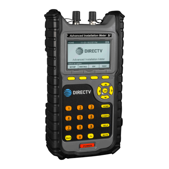
What is the AIM? Overview Congratulations on your new Advanced Installation Meter (AIM) 2! The AIM 2 was developed in collaboration with DIRECTV to provide customized features for installing and troubleshooting DIRECTV satellite receiver systems. The AIM is a rugged meter suitable for both indoor and outdoor use. - Page 14 THIS PAGE LEFT INTENTIONALLY BLANK AIM 2 Operation Manual Page 14...
-
Page 15: Chapter 3
Chapter 3 Getting to Know Your Meter Overview Before using your instrument, take a few minutes to familiarize yourself with the instrument, its basic conventions, and its navigational tools. This section provides a brief overview of the instrument’s features, buttons, and controls. Equipment Supplied with the AIM The AIM comes with the following: •... -
Page 16: A Guided Tour Of Your Aim
A Guided Tour of Your AIM Front View 1. IRD F Connector 2. ODU F Connector 3. Softkeys – Select options that correspond to the onscreen labels above 4. Arrow buttons – Navigate up and down to select an option in a list, as well as right or left when entering information 5. -
Page 17: Right Side View
Right Side View 1. Gigabit Ethernet Port 2. USB 2.0 Port (Type A) 3. DC Charge Port Back View 1. Serial number 2. Battery door AIM 2 Operation Manual Page 17... -
Page 18: Powering Your Meter
Powering Your Meter Power-On To turn on the AIM, press and hold the POWER button until the backlight turns on and the meter sounds a tone. The meter turns on, briefly displays a splash screen, and then displays the HOME screen. To start a job, press SETUP and follow the instructions in “Starting a Job”... -
Page 19: Power-Off
Power-Off Press and hold the POWER button until the SHUT DOWN AIM screen appears. Use the up/down arrow buttons to highlight Shutdown and press OK. The meter turns off. Hard Reset If the AIM is unresponsive to button presses, perform a hard reset. Press and hold the POWER button for 10 to 30 seconds until the meter turns off. -
Page 20: Power Management
Power Management Your AIM is powered by a 6-cell 10.8 Volt 4.4 Ah lithium-ion battery pack. The battery supplies power to the meter, as well as to the LNB and SWiM during installation of an ODU. When fully charged, the AIM’s battery provides sufficient power to install satellite receiver systems in approximately six single-family homes on a single charge. -
Page 21: Battery Charging
Battery Charging You can charge the AIM’s battery from a power outlet using the AC power adapter provided with the meter. After the initial charge, you also can charge the AIM in your vehicle while the vehicle is running using the vehicle power adapter. The AIM can be charged while it is powered off or while it is powered on, which allows you to use the AIM while it is charging. -
Page 22: Battery Replacement
Battery Replacement If necessary, you can replace the AIM’s battery. To obtain a new battery, contact Trilithic. See the Spare Parts List earlier in the manual. You also can return your AIM to Trilithic Customer Service and request that the battery be replaced. - Page 23 5. Connect the battery connector into the slot at the bottom right of the cavity (the slot is keyed to only accept proper insertion). 6. Insert the battery so that the cable is in the bottom left corner, as shown here. Place the upper right corner Wire cable of the battery into the cavity first, so that the foam is compressed to allow the pack to fit snugly.
-
Page 24: Display And Navigation
Display and Navigation Display Screen The AIM has a large LCD display with a backlight for easy readability. Each screen that appears on the display has the following: 1. Title bar – Indicates the screen that is displayed 2. Battery icon – Indicates the power level of the battery 3. -
Page 25: Navigation
Navigation Keep in mind the following guidelines when using the meter buttons to navigate through the AIM’s features: To select a softkey option, press the button below that option. • • To highlight an option in a list, do one of the following: –... -
Page 26: Home Screen
HOME Screen The HOME screen lets you access the AIM’s main features. You can press the HOME button at any time to access the HOME screen. The HOME screen provides four softkeys that correspond to each of the main features of the AIM: •... -
Page 27: Chapter 4
Chapter 4 Setting Up the Meter Overview Before you use your AIM, you should enter registration information, including your ID, name, phone number, and company. You also should review the meter’s settings. You can change the following settings: • Wi-Fi •... -
Page 28: Entering Registration Information
Entering Registration Information Before you use your AIM, you should enter registration information in the meter, including your name, ID, phone number, and company. 1. Press the CONFIG button to go to the CONFIGURATION screen. 2. Select Settings and press SELECT to go to the SETTINGS screen. - Page 29 5. Use the alphanumeric keypad to enter the ID, name, phone number or company. • To delete a character, press the Back button. You also can use left/right arrow buttons to navigate within your entry, or press CLEAR to delete the entry and start over.
-
Page 30: Setting Up The Wi-Fi Connection
Setting up the Wi-Fi Connection 1. Press CONFIG to go to the CONFIGURATION screen. 2. Select Settings and press SELECT to go to the SETTINGS screen. 3. Select Wi-Fi and press SELECT to go to the WI-FI SETTINGS screen. The AIM will scan for all available Wi-Fi networks. - Page 31 4. Select the network you want to connect to, then press SELECT to go to the entry screen. If you don’t see your network listed, select the SCAN softkey to rescan. 5. Use the alphanumeric keypad to enter the password. •...
-
Page 32: Setting Up The Bluetooth Connection
Setting up the Bluetooth Connection 1. Press CONFIG to go to the CONFIGURATION screen. 2. Select Settings and press SELECT to go to the SETTINGS screen. 3. Select Bluetooth and press SELECT to go to the BLUETOOTH SETTINGS screen. The AIM will enable Bluetooth and scan for all available Bluetooth devices. - Page 33 4. Select the device you want to connect to, then press SELECT. The AIM will attempt to pair and connect with the device. If your device is not found, make sure Bluetooth is enabled on your device, and press the SCAN softkey to rescan.
- Page 34 7. On the AIM, “Connected” should now appear next to the Bluetooth device. You can now check for firmware updates using your Bluetooth device’s (e.g. smartphone) internet connection. See the Firmware Update section later in this manual. 8. When finished, press DONE to return to the SETTINGS screen.
-
Page 35: Setting Up The Ethernet Connection
Setting up the Ethernet Connection 1. Press CONFIG to go to the CONFIGURATION screen. 2. Select Settings and press SELECT to go to the SETTINGS screen. 3. Connect the Ethernet cable to the Ethernet port of the AIM. 4. Select ETHERNET and press SELECT to go to the ETHERNET SETTINGS screen. -
Page 36: Ip Settings
IP Settings The IP Settings menu is used to set which type of network connection to establish when logging into a network. 1. Select IP Settings and press SELECT to go to the IP METHOD screen. 2. Select the IP mode for the following options and press SELECT: Select DHCP to automatically obtain an IP •... -
Page 37: Ip Address
IP Address Once IP Settings is set to Manual, you can set each of the network IP address values. 1. Select IP Address and press SELECT to go to the IP ADDRESS screen. 2. Enter the IP address and press SELECT. •... -
Page 38: Changing The Volume Settings
Changing the Volume Settings 1. Press CONFIG to go to the CONFIGURATION screen. 2. Select Settings and press SELECT to go to the SETTINGS screen. 3. Select Volume and press SELECT to go to the VOLUME screen. 4. Use the up/down arrow buttons to select the desired volume setting. -
Page 39: Changing The Display Contrast Or Brightness
Changing the Display Contrast or Brightness 1. Press CONFIG to go to the CONFIGURATION screen. 2. Select Settings and press SELECT to go to the SETTINGS screen. 3. Select Contrast or Brightness and press SELECT to go to the respective screen. 4. -
Page 40: Changing The Time And Date Settings
Changing the Time and Date Settings 1. Press CONFIG to go to the CONFIGURATION screen. 2. Select Settings and press SELECT to go to the SETTINGS screen. 3. Select Time and Date and press SELECT to go to the TIME and DATE screen. 4. - Page 41 5. Select the desired format setting, or use the numeric keypad to enter the time or date. Then press SELECT to return to the TIME and DATE screen. • To delete a character, press the Back button. You also can use the left/right arrow buttons to navigate within your entry, or press CLEAR to delete the entry and start over.
-
Page 42: Changing The Automatic Timer Settings
Changing the Automatic Timer Settings 1. You can change the automatic timer settings for your AIM, including: • Backlight Timer – If no buttons have been pressed on the AIM after the specified time limit, the backlight on the display turns off. The backlight automatically turns back on when you press any button on the meter. - Page 43 3. Select the desired automatic timer setting to adjust (Backlight Timer, Standby Timer, or Shutdown Timer). Then press SELECT to go to the entry screen. 4. Use the numeric keypad to enter a timer setting. • To delete a character, press the Back button.
- Page 44 THIS PAGE LEFT INTENTIONALLY BLANK AIM 2 Operation Manual Page 44...
-
Page 45: Chapter 5
Chapter 5 Setting Up a Job Overview Before you perform tasks for an installation using the AIM, you need to set up the information for the job. Setup tasks include setting up: • Account number • Notes (optional) • Dish type •... -
Page 46: Starting A Job
Starting a Job To start a job, enter the account number for the installation. The AIM stores information about the tasks you perform for the installation in records associated with the account number. For the first job at an installation, you also set the dish type, reverse band/international LNB, switch type, zip code, and notes either by accepting the default settings (based on the previous job), or by changing the default settings. -
Page 47: Modifying The Setup For A Job
Modifying the Setup for a Job You can change the dish type, reverse band/international LNB, switch type, and zip code settings for a new job or the current job from the MODIFY JOB SETUP screen. You also can add notes for the job to include key information about the job, such as the specific room of the installation. -
Page 48: Dish Type
Dish Type 1. On the MODIFY JOB SETUP screen, select Dish Type and press SELECT to go to the DISH TYPE screen. • You also can press the number for an option to highlight it. • To scroll quickly through the dish types, press PAGE UP or PAGE DN softkeys. -
Page 49: Switch Type
Switch Type 1. On the MODIFY JOB SETUP screen, select Switch Type and press SELECT to go to the SWITCH TYPE screen. 2. Select the type of switch for the job and press SELECT. • You also can press the number for an option to highlight it. - Page 50 THIS PAGE LEFT INTENTIONALLY BLANK AIM 2 Operation Manual Page 50...
-
Page 51: Chapter 6
The AIM guides you through the dithering process using a series of audible tones to notify you when the reference values have been obtained. The DIRECTV training materials are the primary source of ODU installation instruction. Those documents supersede the instructions in this manual. -
Page 52: Odu Installation Tasks
The table below indicates which tasks need to be performed for each ODU. When an installation includes two ODUs, you must perform the installation tasks for each ODU. The AIM Install feature guides you through the tasks based on the selected ODU. When using the AIM to align an ODU, refer to the appropriate sections for assistance: •... -
Page 53: Task A. Installation Setup
(see the ODU Installation Tasks table on the previous page). 4. Install the ODU according to the DIRECTV procedure. 5. Connect the AIM’s ODU F Connector to the ODU’s LNB output. -
Page 54: Task B. Coarse Azimuth Adjustment
Task B. Coarse Azimuth Adjustment 1. While monitoring the signal power bar on the COARSE AZ & EL ADJ screen, rotate the ODU on the mast in the azimuth direction until the maximum signal power is reached. 2. Lock down the mounting bracket collar on the mast. -
Page 55: Task D. Tilt Adjustment (95°, 3-Lnb, Slimline-5, And Slimline-5S (Swim) Odus Only)
Task D. Tilt Adjustment (95°, 3-LNB, Slimline-5, and Slimline-5S (SWiM) ODUs Only) 1. Loosen the ODU’s tilt lock-down screws. 2. While monitoring the SNR bar on the TILT ADJ screen, slowly rotate the ODU around the tilt axis until the maximum SNR value is reached. SNR (“signal-to-noise”... - Page 56 6. Refer to the ODU’s dial and use the AIM’s numeric keypad to enter the number of turns it took to return to the reference value (e.g. 4.50 for four and a half turns). Then press OK. 7. Zero out the readout dial on the elevation jack screw.
-
Page 57: Task F. Fine Azimuth Adjustment (Slimline Odus Only)
Task F. Fine Azimuth Adjustment (Slimline ODUs Only) 1. Loosen the ODU’s azimuth lock-down screws. 2. Turn the ODU’s azimuth jack screw counterclockwise 2 turns. 3. On the FINE AZ ADJ screen, press SET REF to set the reference value. The AIM sounds a confirmation tone and displays the reference value. -
Page 58: Performing Eiv Following Odu Installation
If X appears again for one or more orbital slots, you can press EIV DETAIL to determine which tests failed. Troubleshoot any failures following the instructions provided by DIRECTV. • To repeat the alignment process, press REPEAT ALIGN. AIM 2 Operation Manual... - Page 59 3. When you have finished reviewing EIV results on the EIV AT ODU RESULTS screen, you can press DONE to return to the HOME screen. If the installation includes two ODUs, you can press NEXT to return to the SELECT ODU screen and align the other ODU.
- Page 60 THIS PAGE LEFT INTENTIONALLY BLANK AIM 2 Operation Manual Page 60...
-
Page 61: Chapter 7
Chapter 7 Performing EIV Overview Extended Installation Verification (EIV) can be performed at any point in the installation to quickly confirm that the installation is satisfactory for all supported orbital slots. EIV is an easy way to pinpoint any potential problems with the installation. The AIM guides you through the steps for the testing. - Page 62 4. Use the left/right arrow buttons to position the image of the AIM under the location where you are testing. 5. Connect the AIM ODU F connector at the location in the distribution network where you want to test. Then press NEXT to go to the EIV screen.
- Page 63 6. On the EIV screen, you can do one of the following: • To select an individual polarity for the EIV, press OPTIONS. On the EIV OPTIONS screen, highlight the polarity for the EIV. Then press SELECT to continue. • To select the channel for an installation with a DSWiM-13, where the test location is between the DSWiM and IRD,...
- Page 64 EIV DETAIL to determine which tests failed. Troubleshoot any failures following the instructions provided by DIRECTV. To change the location where you are testing, press CHANGE LOC. On the EIV DETAILS screen, you can press NEXT to view the details for another orbital slot, or press BACK to scroll back through the details to the EIV RESULTS screen.
- Page 65 EIV transponder has failed. However, this is not conclusive that the SWiM itself has failed. Troubleshoot any failures following the instructions provided by DIRECTV. 8. When you have finished reviewing EIV results on the EIV RESULTS screen, you can press DONE to return to the HOME screen.
- Page 66 THIS PAGE LEFT INTENTIONALLY BLANK AIM 2 Operation Manual Page 66...
-
Page 67: Chapter 8
Chapter 8 Performing Other Network Tests Overview If there is a problem with a DIRECTV installation, you can run network tests to help you troubleshoot the problem. These tests include: • Guided Mode • EIV Plus • Satellite Tune test •... -
Page 68: Using Guided Mode
Using Guided Mode Guided Mode is an optimized troubleshooting process that lets you quickly and easily identify equipment failures in an installation. The AIM guides you through a series of tests to pinpoint the source of the failures. After each test, the AIM identifies the faulty component or recommends the next location for testing to isolate the issue. - Page 69 4. Verify the setup information for the job. Then press START to go to the GUIDED CONFIGURATION screen. If the setup information is incorrect, press SETUP to go to the MODIFY JOB SETUP screen. Follow the instructions in the Starting a Job section in Chapter 5 to modify the setup information.
- Page 70 6. Connect the AIM ODU F connector at the location in the distribution network indicated on the display. Then press RUN TEST and wait for the results. 7. On the GUIDED RESULTS screen, review the results of the EIV Plus. Then do one of the following: •...
- Page 71 8. On the GUIDED DETAILS screen, review the possible problems with the installation. Then do one of the following: • To view results of the EIV Plus, press EIV PLUS RESULTS to go to the GUIDED EIV PLUS RESULTS screen. Go to Step 9.
- Page 72 10. On the GUIDED DATA screen, review the results for each EIV Plus performed in Guided Mode for the installation. Results for each EIV Plus are listed in sequential columns; a satisfactory result is indicated by a checkmark and a problem is indicated by an X. Press PAGE UP or PAGE DOWN to •...
-
Page 73: Performing Eiv Plus
Performing EIV Plus You can use EIV Plus to perform a series of tests to help you quickly identify potential problems with an installation. EIV Plus performs the same tests as in Guided Mode, but requires you to interpret the results and determine the next steps for troubleshooting (instead of providing a recommendation). - Page 74 If an EIV Plus test fails and the failure could be due to inclement weather, you can use the Rain Mode feature to continue troubleshooting with EIV Plus. Rain Mode allows for a slight degradation in the RF signal in order to account for environmental conditions, allowing you to continue troubleshooting beyond the ODU.
- Page 75 5. Use the left/right arrow buttons to position the image of the AIM under the location where you are testing. 6. Connect the AIM ODU F connector at the location in the distribution network where you want to test. Then press NEXT to go to the EIV PLUS TEST screen.
- Page 76 Press REPEAT EIV PLUS to confirm the problem. • If X appears again for one or more orbital slots, you can press EIV PLUS DETAIL to determine which tests failed. Troubleshoot any failures following the instructions provided by DIRECTV. AIM 2 Operation Manual Page 76...
- Page 77 If it is raining and an attempt to realign the ODU fails, you can enable Rain Mode to account for environmental conditions and continue troubleshooting. Press Fn and then 4 to enable Rain Mode. Press Repeat Test and wait for the results of the test. The Rain Mode icon appears on the Results screen to indicate the test was run in Rain Mode.
-
Page 78: Performing A Satellite Tune Test
Performing a Satellite Tune Test You can use the AIM’s Satellite Tune feature to tune to any DIRECTV transponder. Connecting the AIM in different locations in the distribution network, you can progressively test each segment of the connection between the ODU and the IRD to locate a problem. - Page 79 6. Connect the AIM ODU F connector at the location in the distribution network where you want to test. To test between the ODU and the multiswitch, disconnect the cable connecting the ODU to the multiswitch and connect it to the AIM’s ODU F connector.
- Page 80 • Indication as to whether the transponder signal is above the power lock threshold. 13. Troubleshoot any problems following the instructions provided by DIRECTV. • To repeat the test at a different location, press CHANGE LOC. Then go to Step •...
-
Page 81: Performing A Transponder Survey
Performing a Transponder Survey You can use the AIM’s Transponder Survey feature to record the signal power, signal-to-noise ratio (SNR), frequency offset, and lock status for all transponders that can be received using the selected equipment. This can help to determine the location of a problem for an installation. Connecting the AIM in the distribution network, you can progressively test each segment of the connection between the ODU and the IRD to locate a problem. - Page 82 6. Connect the AIM ODU F connector at the location in the distribution network where you want to test. 7. Press NEXT to go to the TRANSPONDER SURVEY screen. 8. If the installation includes two ODUs, highlight the ODU to test and press SELECT to continue.
- Page 83 10. If you want to set the SWiM (or DSWiM) channel for the transponder survey, do the following: Press OPTIONS. • • On the TR SURVEY OPTIONS screen, highlight Set SWiM Ch. (Connect SWiM). • Highlight the desired channel and press SELECT to go to the TRANSPONDER SURVEY screen.
- Page 84 ODU used • SWiM channel used 14. Troubleshoot any problems following the instructions provided by DIRECTV. To repeat the test at a different location, press CHANGE LOC 15. Press DONE to return to the TEST screen. Use PAGE UP and PAGE DN to scroll quickly through test results.
-
Page 85: Performing A Cable Resistance Test
Performing a Cable Resistance Test You can use the AIM’s Cable Resistance test feature to help determine whether there is a problem with a cable used in the distribution network. To complete this test, you must use the 25 Ω Cable Test Load (provided with the AIM). By placing the Cable Test Load on the end of a cable, you can determine the resistance value for the cable. - Page 86 25 Ω Cable Test Load. 9. Troubleshoot any problems following the instructions provided by DIRECTV. To repeat the Cable Resistance test, press REPEAT. 10. Press DONE to return to the TEST screen.
-
Page 87: Performing An In-Line Test
Performing an In-Line Test You can use the AIM’s In-Line test feature to help determine the cause of a problem in an installation. Connecting the AIM in series with the equipment, you can progressively test each segment of the connection between the ODU and the IRD to locate a problem. The AIM can measure the voltage, current, and 22 kHz signals to verify that the correct control signals are being transmitted through the coaxial cable. - Page 88 Indication as to whether DiSEqC commands are being received by the multiswitch (MSW) and BBC. 9. Troubleshoot any problems following the instructions provided by DIRECTV. 10. Press DONE to return to the TEST screen. As messages are received from the multiswitch (MSW) and BBC, the multiswitch port and BBC frequency range flash bold.
-
Page 89: Performing A Swim Lf Power Test
The screen shows whether the SWiM LF power level is sufficient. 7. Troubleshoot any problems following the instructions provided by DIRECTV. To repeat the SWiM LF Power test in case of a failure, press RETRY. 8. Press DONE to return to the TEST screen. -
Page 90: Performing A Swim Channel Assignments Test
Performing a SWiM Channel Assignments Test You can use the AIM’s SWiM Channel Assignments test feature to view the Receiver IDs (RIDs) and assigned SWiM or DSWiM channels for each IRD in the installation. If you suspect that the network could be oversubscribed, the results show whether all available SWiM or DSWiM channels are used, indicating the possibility that the number of IRDs in the network exceeds the SWiM’s capacity. - Page 91 RID and the SWiM channel used. The number of available SWiM channels is also indicated. Troubleshoot any problems following the instructions provided by DIRECTV. 7. Press DONE to return to the TEST screen. AIM 2 Operation Manual Page 91...
- Page 92 THIS PAGE LEFT INTENTIONALLY BLANK AIM 2 Operation Manual Page 92...
-
Page 93: Chapter 9
Chapter 9 Managing Records Overview The AIM stores information for each account, including the results for each EIV, EIV Plus, Guided Mode test, and Transponder Survey. Screenshots are also stored as records. For all accounts, you can: • View records •... -
Page 94: Viewing Records
Viewing Records You can view records for tests performed on the AIM, including EIV, EIV Plus, Guided Mode, and Transponder Survey, as well as screenshots. You can select a record to view from a list of all records on the AIM, or view records by account number. 1. - Page 95 4. Highlight the record you want to view and press SELECT. The VIEW INFO screen for the selected record appears. 5. On the VIEW INFO screen, you can do the following (example screens are shown): • Copy, move, or delete the record by pressing OPTIONS.
- Page 96 6. On the VIEW DATA screens, you can do the following (example screens are shown): • Scroll through the results using PAGE UP and PAGE DN. • View the next data screen by pressing NEXT. • Return to the VIEW RECORDS screen by pressing DONE.
-
Page 97: Deleting Records
Deleting Records You can delete records stored on the AIM, including: • An individual record • All records for a selected account • All records for all accounts • All records of a selected type (EIV, EIV Plus, Guided Mode, Transponder Survey, or Screenshots). - Page 98 3. To delete all records on the AIM or records of a selected type, do the following on the QUICK DELETE RECORDS screen: • Highlight the type of records to delete and press SELECT. You can select Delete All Records to delete all records on the AIM, or select a specific type of records to delete.
- Page 99 5. To delete all records for an account, do the following on the VIEW RECORDS BY ACCOUNT screen. • Highlight the account number and press OPTIONS. • On the Options window, highlight Delete... and press OK. • Highlight the type of records to delete and press OK.
-
Page 100: Transferring Records
Transferring Records You can transfer records from your AIM to a PC using a USB flash drive. You also can transfer records from a USB flash drive to the AIM (see page 92). You can transfer: • An individual record •... - Page 101 4. To transfer all records on the AIM or records of a selected type, do the following on the QUICK COPY RECORDS (or QUICK MOVE RECORDS) screen: • Highlight the type of records to transfer and press SELECT. You can select Copy All Records (or Move All Records) to transfer all records on the AIM, or select a specific type...
- Page 102 6. To transfer all records for an account, do the following on the VIEW RECORDS BY ACCOUNT screen: • Highlight the account number and press OPTIONS. • On the Options window, highlight Copy... or Move... and press OK. • Highlight the type of records to transfer and press OK.
-
Page 103: Transferring Records From A Usb Flash Drive To The Aim
Transferring records from a USB flash drive to the AIM 1. Insert the USB flash drive in the appropriate USB connector on the meter. 2. Press CONFIG to go to the CONFIGURATION screen. 3. Highlight Records and press SELECT to go to the RECORDS MAIN screen. - Page 104 THIS PAGE LEFT INTENTIONALLY BLANK AIM 2 Operation Manual Page 104...
-
Page 105: Chapter 10
Chapter 10 Updating the Meter Overview You can update your AIM as new features become available via the Internet or USB flash drive. You can update the meter firmware without plugging the AIM into a power outlet, as long as the battery icon on the display shows at least two remaining bars of power. -
Page 106: Update Firmware From The Internet
Update Firmware from the Internet The AIM can update firmware from an Ethernet connection or via Wi-Fi. Make sure the Ethernet connection has been set up and you have connected a Ethernet cable to the port on the AIM. If using Wi-Fi, make sure the Wi-fi network has been set up. -
Page 107: Chapter 11
Chapter 11 Appendix Specifications Frequency Range 250 MHz to 2150 MHz Signal Level Range -10 to -69 dBmV RF Input Connector Replaceable “F” connector (2) Input Impedance 75 Ω LNB Power Supply 13 Volts / 18 Volts SWiM Power Supply 21 Volts Wi-Fi (802.11 b,g and n, 2.4 GHz);... - Page 108 Made in U.S.A.