Table of Contents
Advertisement
Available languages
Available languages
SmartRack
1.
2.
3.
4.
5.
Register your product for quicker service and ultimate peace of mind.
You could also win an ISOBAR6ULTRA surge protector-a $100 value!
Owner's Manual
Models: SR42UBCL, SR48UBCL
(Series Numbers: AGAC7761, AGAC7454)
PROTECT YOUR INVESTMENT!
www.tripplite.com/warranty
1111 W. 35th Street, Chicago, IL 60609 USA • www.tripplite.com/support
Copyright © 2019 Tripp Lite. All rights reserved.
Enclosures
®
2
6.
2
3
3
7.
3
4
5
5
8.
6
9.
6
6
6
6
7
8
8
8
8
8
9
9
1
10
10
10
11
11
11
11
12
12
13
25
37
Advertisement
Chapters
Table of Contents

Related Manuals for Tripp Lite SmartRack AGAC7761 Series


Summary of Contents for Tripp Lite SmartRack AGAC7761 Series
-
Page 1: Table Of Contents
Owner’s Manual SmartRack Enclosures ® Models: SR42UBCL, SR48UBCL (Series Numbers: AGAC7761, AGAC7454) Important Safety Instructions Combination Locks 6.1 Setting and Resetting the Overview Combination Lock Feature Identification 6.2 Using the Combination Lock Enclosure Installation Equipment Installation 4.1 Preparation 7.1 Cage Nuts 4.2 Unpacking 7.1.1 Installing Cage Nuts 4.3 Placement... -
Page 2: Important Safety Instructions
1. Important Safety Instructions SAVE THESE INSTRUCTIONS All sections of this manual contain instructions and warnings that should be followed during the installation and use of the SmartRack Enclosures described in this manual. Read all instructions and warnings thoroughly before attempting to move, install or use the SmartRack Enclosures described in this manual. -
Page 3: Feature Identification
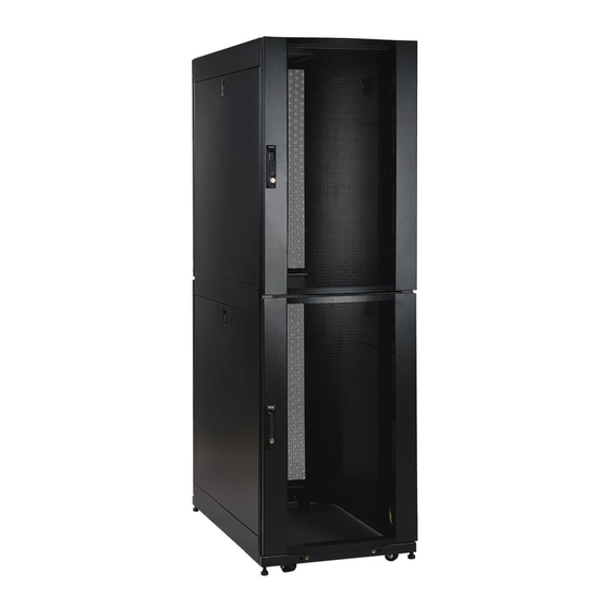
3. Feature Identification Model SR42UB is shown. The other models have similar features, with the differences noted. Roof Panel Locking, Reversible Split Front and Rear Doors Locking Side Panels (25U enclosures use 2 side panels instead of 4. Side panels are not included with “EXP” models.) Cable Management Rails Casters and Levelers... -
Page 4: Unpacking
4. Enclosure Installation 4.2 Unpacking Note: If the enclosure is an “SP1” model with a shock pallet, follow the special unpacking instructions attached to the shipping container instead of the unpacking instructions in this section. All warnings still apply. Confirm that the shipping container is upright and stable, then use a utility blade to cut the shrink-wrap securing the corner protectors. -
Page 5: Placement
4. Enclosure Installation Position at least one person at the front of the enclosure and one person at the rear of the enclosure. Slowly push the enclosure toward the back of the shipping pallet until all four casters go over the edge of the pallet and touch the floor. WARNING: Use at least one assistant when removing the enclosure from the pallet. -
Page 6: Ground Connection
4. Enclosure Installation In order to secure the cabinet to the building structure for stability, attach the 2 shipping brackets using the hardware that attached the enclosure to the shipping pallet. Use a 13 mm open-end wrench to connect the brackets to the outer or inner bracket mounting points of the enclosure. -
Page 7: Reversing Doors
5. Enclosure Configuration 5.2 Reversing Doors Remove the screw connecting the ground wire to the inside of the door. Remove the combination lock, cam and screw plate from the door of the enclosure as shown. Remove the doors by following the steps in the previous section. Remove the door hinges from the enclosure, rotate them 180 degrees and attach them on the opposite side of the enclosure. -
Page 8: Adding Or Removing Roof Panel
5. Enclosure Configuration Reinstall the combination lock, so the unit is right-side up. Slide the lock handle through the opening, install the cam, and then secure the lock using the screws and screw plate as shown. 5.3 Adding or Removing Roof Panel WARNING: Do not attempt to use the roof panel for weight-bearing purposes other than those explicitly described and approved by Tripp Lite. -
Page 9: Reinstalling Side Panels
5. Enclosure Configuration Tilt the top of the panel away from the enclosure. Lift the panel away from the brace that supports it. 5.4.2 Reinstalling Side Panels To Reinstall Side Panels, Reverse Steps 1-3 5.5 Combining (Baying) Enclosures WARNING: Combining enclosures is not a substitute for stabilizing the enclosures. Each enclosure in a bay of combined enclosures requires the same stabilizing measures as a standalone enclosure. -
Page 10: Combination Locks
5. Enclosure Configuration Connect each bracket to the adjoining enclosure using the screws you removed in step 2, but do not tighten the screws completely. Adjust the position of the enclosures as needed. If you want the centers of the enclosures to be 24 inches (61 cm) apart, use the outside hole of the bracket . -
Page 11: Equipment Installation
7. Equipment Installation WARNING: Do not install equipment until you have stabilized the enclosure. Install heavier equipment first and install it toward the bottom of the enclosure. Install equipment starting from the bottom of the enclosure and proceeding toward the top of the enclosure - never the reverse. If using sliding equipment rails, be careful when extending the rails. -
Page 12: Specifications
8. Specifications Load Capacity* Unit Dimensions Shipping Dimensions Model Static Rolling Height Width Depth Weight Height Width Depth Weight 3000 lb 2250 lb 49 in 23.63 in 43 in 195 lb 55 in 27.75 in 47 in 218 lb SR25UB (1363 kg) (1022 kg) (1245 mm) -
Page 13: Español
Manual del propietario Racks SmartRack ® Modelos: SR42UBCL, SR48UBCL (Número de serie: AGAC7761, AGAC7454) Instrucciones de seguridad Cerraduras con combinación importantes 6.1 Configuración y reconfiguración de la cerradura con combinación Generalidades 6.2 Uso de la cerradura con combinación Identificación de las características 15 Instalación de equipos Instalación del rack 7.1 Tuercas en jaula... -
Page 14: Instrucciones De Seguridad
1. Instrucciones de seguridad importantes GUARDE ESTAS INSTRUCCIONES Todas las secciones de este manual contienen instrucciones y advertencias que deben seguirse durante la instalación y el uso de los racks SmartRack descritos en este manual. Lea atentamente todas las instrucciones y advertencias antes de intentar mover, instalar o usar los racks SmartRack descritos en este manual. -
Page 15: Identificación De Las Características
3. Identificación de las características Se muestra el modelo SR42UB. Los otros tienen características similares, con las diferencias indicadas. Panel de techo Puertas divididas frontales y traseras, reversibles y con traba Paneles laterales con traba (los racks 25U usan 2 paneles laterales en lugar de 4. No están incluidos en los modelos “EXP”). Rieles para administración de cables Ruedas y niveladores... -
Page 16: Desembalaje
4. Instalación del rack 4.2 Desembalaje Nota: Si el rack es un modelo “SP1” con pálet contra golpes, siga las instrucciones de desembalaje especiales adjuntas al contenedor de envío en lugar de las de esta sección. Siguen aplicándose todas las advertencias. Confirme que el contenedor de envío esté... -
Page 17: Ubicación
4. Instalación del rack Ubique al menos a una persona frente al rack y otra en la parte de atrás. Empuje lentamente el rack hacia la parte de atrás del pálet de envío hasta que las cuatro ruedas pasen sobre el borde del pálet y toquen el piso. -
Page 18: Conexión A Tierra
4. Instalación del rack A fin de asegurar el gabinete a la estructura del edificio para tener estabilidad, fije los 2 soportes de embarque usando los accesorios que sujetan el gabinete a la tarima de embarque. Use una llave de boca de 13 mm para conectar los soportes a los puntos de montaje externos internos del rack. -
Page 19: Cómo Invertir Las Puertas
5. Configuración del rack 5.2 Cómo invertir las puertas Quite el tornillo que conecta el alambre a tierra con el interior de la puerta. Quite la cerradura de combinación, la leva y la placa atornillada de la puerta del rack como se muestra. -
Page 20: Cómo Agregar O Quitar El Panel De Techo
5. Configuración del rack Vuelva a instalar la cerradura de combinación con el lado derecho hacia arriba. Deslice el mango de la cerradura a través de la abertura, instale la leva y luego fije la cerradura con los tornillos y la placa tal como se muestra. -
Page 21: Cómo Reinstalar Los Paneles Laterales
5. Configuración del rack Incline la parte superior del panel hacia afuera del rack. Levante el panel de la abrazadera que lo sostiene. 5.4.2 Cómo reinstalar los paneles laterales Para reinstalar los paneles laterales, siga los pasos 1 a 3 en sentido inverso. 5.5 Combinación de racks ADVERTENCIA: La combinación de racks no sustituye su estabilización. -
Page 22: Cerraduras Con Combinación
5. Configuración del rack Conecte cada soporte al rack adyacente usando los tornillos que quitó en el paso 2, pero no los ajuste por completo. Ajuste la posición de los racks como sea necesario. Si desea que los centros de los racks estén a 24 pulg. (61 cm), use el orificio externo del soporte . -
Page 23: Instalación De Equipos
7. Instalación de equipos ADVERTENCIA: No instale equipos hasta que haya estabilizado el rack. Instale primero los equipos más pesados en la parte inferior del rack. Instálelos de abajo hacia arriba, nunca en sentido contrario. Si usa rieles para equipos deslizantes, tenga cuidado al extender los rieles. No extienda más de un juego de rieles por vez. -
Page 24: Especificaciones
8. Especificaciones Capacidad de carga* Dimensiones de la unidad Dimensiones de envío Modelo Estática Rodante Altura Ancho Prof. Peso Altura Ancho Prof. Peso 3000 lb 2250 lb 49 in 23.63 in 43 in 195 lb 55 in 27.75 in 47 in 218 lb SR25UB (1363 kg) -
Page 25: Français
Guide d’utilisation Bâtis d’équipement électronique SmartRack ® Modèles: SR42UBCL, SR48UBCL (Numéro de série : AGAC7761, AGAC7454) Importantes consignes de sécurité Serrures à combinaison Vue d’ensemble 6.1 Réglage et réinitialisation de la serrure à combinaison Définition des caractéristiques 6.2 Utilisation de la serrure à combinaison Installation du bâti Installation de l’équipement 4.1 Préparation... -
Page 26: Importantes Consignes De Sécurité
1. Importantes consignes de sécurité ENREGISTRER CES CONSIGNES Toutes les sections du présent guide contiennent des consignes et des mises en garde qui doivent être respectées pendant l’installation et l’utilisation des bâtis SmartRack décrits dans le guide. Lire attentivement toutes les consignes et mises en garde avant de tenter de déplacer, d’installer ou d’utiliser les bâtis SmartRack décrits dans le présent guide. -
Page 27: Définition Des Caractéristiques
3. Définition des caractéristiques Illustration du modèle SR42UB. Les autres modèles présentent des caractéristiques semblables, les différences étant indiquées. Plateau supérieur Portes avant et arrière réversibles en deux parties verrouillables Panneaux latéraux verrouillables (les bâtis 25U ont 2 panneaux latéraux au lieu de 4. Les modèles « EXP » ne sont pas munis de panneaux latéraux.) Rails de gestion de câbles Roulettes et patins réglables... -
Page 28: Déballage
4. Installation du bâti 4.2 Déballage Remarque : Si le bâti est un modèle « SP1 » équipé d’une palette antichoc, suivre les consignes de déballage spéciales figurant sur le contenant d’expédition plutôt que les consignes de déballage figurant dans la présente section. Toutes les mises en garde restent valables. S’assurer que le contenant d’expédition est bien droit et stable, puis utiliser une lame utilitaire pour couper l’emballage moulant fixant les cornières de protection. -
Page 29: Mise En Place
4. Installation du bâti Demander à au moins une personne de se positionner devant le bâti et à une autre de se positionner derrière. Pousser doucement le bâti vers l’arrière de la palette d’expédition jusqu’à ce que les quatre roulettes soient sur le bord de la palette et touchent le sol. MISE EN GARDE : Demander l’aide d’au moins une personne pour retirer le bâti de la palette. -
Page 30: Conexión A Tierra
4. Installation du bâti Pour retenir l’armoire à la structure du bâtiment pour fournir une stabilité, fixer les 2 supports d’expédition en utilisant la quincaillerie qui retenait le boîtier à la palette d’expédition. Utiliser une clé à fourche 13 mm pour relier les supports au point de montage des supports extérieur intérieur ddu bâti. -
Page 31: Renversement Des Portes
5. Configuration du bâti 5.2 Renversement des portes Retirer la vis reliant le fil de terre à l’intérieur de la porte. Retirer la serrure à combinaison, la came et le plateau-vis de la porte du bâti comme sur le schéma. Retirer les portes en suivant les étapes mentionnées dans la section précédente. -
Page 32: Installation Ou Retrait Du Plateau Supérieur
5. Configuration du bâti Réinstaller la serrure à combinaison en plaçant le côté droit en haut. Faire coulisser la poignée de verrouillage par l’ouverture, installer la came, puis fixer la serrure au moyen des vis et du plateau-vis comme sur le schéma. 5.3 Installation ou retrait du plateau supérieur MISE EN GARDE : Ne pas essayer d’utiliser le plateau supérieur à... -
Page 33: Réinstallation Des Panneaux Latéraux
5. Configuration du bâti Incliner le haut du panneau pour l’écarter du bâti. Extraire le panneau de la cale qui le soutient. 5.4.2 Réinstallation des panneaux latéraux Pour réinstaller les panneaux latéraux, exécuter les étapes 1 à 3 en sens inverse. 5.5 Combinaison (union) des bâtis MISE EN GARDE : La combinaison de bâtis ne remplace pas la stabilisation des bâtis. -
Page 34: Serrures À Combinaison
5. Configuration du bâti Relier chaque support au bâti adjacent au moyen des vis retirées à l’étape 2, mais ne serrer pas les vis à fond. Ajuster la position des bâtis au besoin. Pour espacer les centres des bâtis de 24 pouces (61 cm), prendre comme repère le trou externe du support . -
Page 35: Installation De L'équipement
7. Installation de l’équipement MISE EN GARDE : Ne pas installer l’équipement avant d’avoir stabilisé le bâti. Installer d’abord l’équipement lourd vers le fond du bâti. Installer l’équipement en allant du fond du bâti vers le haut – jamais dans le sens inverse. Si des rails glissières sont utilisés, faire attention au moment d’étirer les rails. -
Page 36: Spécifications
8. Spécifications Capacité nominale* Dimensions de l’appareil Dimensions d’expédition Modèle Immobile Mobile Hauteur Largeur Profondeur Poids Hauteur Largeur Profondeur Poids 3000 lb 2250 lb 49 in 23.63 in 43 in 195 lb 55 in 27.75 in 47 in 218 lb SR25UB (1363 kg) (1022 kg) -
Page 37: Русский
Руководство пользователя Шкафы серии SmartRack ® Модели: SR42UBCL, SR48UBCL (номера серий: AGAC7761, AGAC7454) Важные указания по технике безопасности Кодовые замки 6.1 Настройка и перенастройка кодового замка Краткое описание 6.2 Порядок использования кодового замка Схема расположения функциональных элементов 39 Установка оборудования Порядок... -
Page 38: Важные Указания По Технике Безопасности
1. Важные указания по технике безопасности СОХРАНИТЕ НАСТОЯЩИЕ УКАЗАНИЯ Во всех разделах настоящего руководства содержатся указания и предупреждения, которые необходимо соблюдать в процессе установки и эксплуатации описанных в нем шкафов серии SmartRack. Внимательно ознакомьтесь со всеми указаниями и предупреждениями перед выполнением любых действий, связанных с перемещением, установкой или эксплуатацией... -
Page 39: Схема Расположения Функциональных Элементов
3. Схема расположения функциональных элементов На рисунке представлена модель SR42UB. Другие модели имеют аналогичные функциональные элементы с указанными различиями. Верхняя панель Запираемые передняя и задняя дверцы разрезной конструкции с возможностью навешивания на любую сторону Запирающиеся боковые панели (в шкафах высотой 25U используются две боковые панели вместо четырех. Модели "EXP" боковыми панелями не комплектуются). Направляющие... -
Page 40: Распаковка
4. Порядок установки шкафа 4.2 Распаковка Примечание. Для шкафа одной из моделей SP1 с ударозащищенным поддоном следуйте специальным указаниям по распаковке, прилагаемым к транспортировочному контейнеру, вместо аналогичных указаний, изложенных в настоящем разделе. При этом все предупреждения остаются в действии. Убедитесь в том, что транспортировочный контейнер находится в устойчивом вертикальном положении, после чего с помощью универсального... -
Page 41: Размещение
4. Порядок установки шкафа По меньшей мере один человек должен находиться перед шкафом и один человек — позади него. Медленно толкайте шкаф в сторону задней части транспортировочного поддона до тех пор, пока все четыре ролика не выйдут за край поддона и не коснутся... -
Page 42: Заземление
4. Порядок установки шкафа Для крепления шкафа к строительной конструкции с целью обеспечения устойчивости прикрепите 3 транспортировочных кронштейна с помощью крепежных приспособлений, использовавшихся для крепления шкафа к транспортировочному поддону. С помощью рожкового ключа размером 13 мм закрепите кронштейны во внешних или... -
Page 43: Перестановка Дверец
5. Компоновка шкафа 5.2 Перестановка дверец Выверните винт, соединяющий провод заземления с внутренней поверхностью дверцы. Снимите с дверцы шкафа кодовый замок, замочный клин и резьбовую пластину, как показано на рисунке. Снимите дверцы в порядке, изложенном в предыдущем разделе. Снимите дверные петли со шкафа, разверните их на 180 градусов и закрепите на противоположной стороне шкафа. Примечание. -
Page 44: Установка/Снятие Верхней Панели
5. Компоновка шкафа Установите на место кодовый замок таким образом, чтобы он находился правой стороной вверх. Проденьте дужку замка в отверстие, вставьте замочный клин и зафиксируйте замок с помощью винтов и резьбовой пластины, как показано на рисунке. 5.3 Установка/снятие верхней панели ВНИМАНИЕ! Не... -
Page 45: Повторная Установка Боковых Панелей
5. Компоновка шкафа Наклоните верхнюю часть панели по направлению от шкафа. Выньте панель из фиксатора. 5.4.2 Повторная установка боковых панелей Для установки боковых панелей на место следует повторить шаги 1-3 в обратном порядке 5.5 Совмещение шкафов (установка в ряд) ВНИМАНИЕ! Объединение шкафов не может служить заменой обеспечению их устойчивости. Каждый шкаф, установленный в ряд с объединенными с ним шкафами, требует тех же действий... -
Page 46: Кодовые Замки
5. Компоновка шкафа Присоедините каждую скобу к соседнему шкафу с помощью винтов, вывернутых на шаге 2, но не затягивайте винты полностью. При необходимости отрегулируйте положение шкафов. Если вы хотите, чтобы расстояние между центрами шкафов составляло 61 см, используйте внешнее отверстие скобы . -
Page 47: Установка Оборудования
7. Установка оборудования ВНИМАНИЕ! Не устанавливайте оборудование до обеспечения устойчивости шкафа. Сначала установите оборудование, которое следует разместить в нижней части шкафа. Устанавливайте оборудование начиная с низа шкафа по направлению вверх — и ни в коем случае не наоборот. При использовании направляющих для установки оборудования соблюдайте... -
Page 48: Технические Характеристики
8. Технические характеристики Допустимая нагрузка* Габаритные размеры Транспортные габариты Модель Стационарная Роликовая Высота Ширина Глубина Масса Высота Ширина Глубина Вес SR25UB 1363 кг 1022 кг 1245 мм 600 мм 1092 мм 88,6 кг 1397 мм 705 мм 1194 мм 99,1 кг SR25UBEXP 1363 кг...