Table of Contents
Advertisement
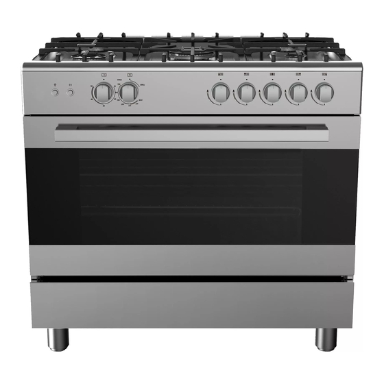
Service Manual For Free-standing Oven
( 90X60 Gas COOKTOP and Electric oven )
This service manual is not available to the general users, but only applies to professional
technicians with relevant qualifications. Any incorrect maintenance may result in other
dangers!
The power and gas supply must be cut off before maintenance!
A new power cord which meets the relevant technical requirements must be used once
possible hidden malfunctions are found with the current power cord (refer to this
Manual)!
Please read carefully all safety warnings in this Manual before maintenance!
The product is prohibited from using until test is conducted as per relevant regulations
after maintenance!
This service manual applies to many models, so the specific operations please prevail in
kind!
Warnings
V2.0
Mar, 2014
Advertisement
Table of Contents
Troubleshooting

Related Manuals for Midea VS96048D


Summary of Contents for Midea VS96048D
- Page 1 Service Manual For Free-standing Oven ( 90X60 Gas COOKTOP and Electric oven ) Warnings This service manual is not available to the general users, but only applies to professional technicians with relevant qualifications. Any incorrect maintenance may result in other dangers! ...
-
Page 2: Table Of Contents
Contents Precaution .................................. 1 1.1. Safety Precaution ..............................1 1.2. Warning ................................1 Dimension................................... 1 Function ..................................2 3.1 Flame thrower function............................2 3.2 Oven function ................................2 Attention ..................................3 Circuit diagram ................................4 Disassembly ................................5 6.1 Disassembly of cooktop ............................5 6.2 Disassembly of knob .............................. -
Page 3: Precaution
Precaution 1.1. Safety Precaution 1. To prevent injury to the user or other people and property damage, the following instructions must be followed. 2. Incorrect operation due to ignoring instructions will cause harm or damage. 3. Before maintenance, please read carefully the following instructions at first. 1.2. -
Page 4: Function
Function 3.1 Flame thrower function Flame thrower 3 Flame thrower 2 Flame thrower 4 Flame thrower 1 Flame thrower 5 One-to-one match Switch 1 ~Flame thrower 1 Switch 2 ~Flame thrower 2 Switch 1~5 Switch 3 ~Flame thrower 3 (from left to right) Switch 4 ~Flame thrower 4 Switch 5 ~Flame thrower 5 3.2 Oven function... -
Page 5: Attention
Attention The oven door shall be opened to contact the upper part and back of the oven cavity if the oven is required to be lifted or moved. It is prohibited from using door handle directly to lift the oven(see the following figure). -
Page 6: Circuit Diagram
Circuit diagram Circuit diagram for gas oven Page4... -
Page 7: Disassembly
Disassembly 6.1 Disassembly of cooktop Step 1: Remove the pan supports, sprayers and burner caps on the cooktop. Step2: Remove the cook top lid Step 3: Unscrew the screws used on the burner cup Page5... -
Page 8: Disassembly Of Knob
Step 4: Unscrew rear section. Screw Step 5: Lift the rear of cook top gently and push forward to front. 2.PUSH FORWARD 1.PUSH UP 6.2 Disassembly knob Step 1: Lift the knob base and pull it out Page6... -
Page 9: Disassembly Of Drawer
6.3 Disassembly of drawer Step 1: Open the drawer to a maximum angle. Step 2: Remove the four screws attached to the drawer hinge with a screwdriver. 6.4 Disassembly of oven door In reference to the instruction manual “Removing and fitting the appliance door”. Page7... -
Page 10: Overview Of Inside Structure
6.5 Overview of inside structure Valve body *5 Thermo switch 55℃ normal open Bottom cup*5 The main gas tupe Flame ignitor Rotating motor Picture 1.Inside structure Heating element (upper) Cooling motor Lamp Rotating motor Heating element (Bottom) Terminal block Page8... -
Page 11: Disassembly Of Heating Element(Upper)
6.6 Disassembly the heating element(upper) Step 1: disassembly the rear panel. screw Step 2: Pull out the terminal of upper heating element. Heater Terminals Page9... - Page 12 Step 3:Open the door, take out the Cooking grid ,Cooking grid(with cooking pan) and cooking pan. cooking grid cooking grid (with cooking pan) cooking pan door Step 4:Unscrew four screws, take out the heating element(upper) Screw Page10...
-
Page 13: Disassembly Of Heating Element(Bottom)
6.7 Disassembly the heating element(bottom) Step 1: screws, open the rear panel. Disassemble screw Step 2: Pull out the terminal, unscrew the bracket of heating element(bottom). Screw Page11... -
Page 14: Disassembly Of Oven Lamp
6.8 Disassembly of oven lamp Step 1: Disassemble the cooktop and pull out the lamp wire and ground wire. Ground wire Lamp wire Step 2: Remove the bulb by screwing the bulb cover off the cavity only if the bulb is required to be replaced. Bulb cover Bulb Page12... -
Page 15: Disassembly Of Rotary Motor
6.9 Disassembly of rotary motor Step 1: Disassemble the control panel. Step 2:Ddisassemble the left side board to expose the rotary motor. Step 3: Pull out the wire harness on the rotary motor. wire harness Page13... - Page 16 Step 4: Remove the rotary motor and loosen the fixed screws at both ends of the rotary motor support. screw Page14...
-
Page 17: Troubleshooting
Trouble shooting 7.1 Gas trouble shooting Phenomenon Inspection method Repair measures 1 Examine if the gas source of the product is in conformity with the (I)The burner is detected with application requirements; 2 Examine if the gas pressure is in yellow flame. -
Page 18: Electronics Troubleshooting
7.2 Electronics troubleshooting Phenomenon Cause Solution 1 The heating element is damaged. 1 Replace the heating element (I) The heating elements are 2 Wire fault(open circuit) 2 Change the wireharness not heated. 3 Failure on heating element control switch 3 Change the control switch 1.The oven lamp is damaged;... -
Page 19: Maintenance And Test
Maintenance and test 8.1 Air leakage test Tool: Air leakage device, soap water 1. Professional repair procedures a) Connect product to the air leakage device and set the test pressure at 15kPa; b) The plug valve shall be kept closed and the gas pipelines may be tested its leakage through air leakage device;... -
Page 20: Replacement Of Injector And Adjustment Of Valve
8.2 Replacement of injector and adjustment of valve Tool: Inner hexagon S7 sleeve/straight screwdriver of 2mm diameter Steps for operation: a) Disassembly respectively the cooktop, the injectors of upper and lower burners with sleeve. b) Get a corresponding substitute injector(see the following table), apply thread sealant around its screw thread and reassemble with sleeve. -
Page 21: Replacement Of Valve Body
8.3 Replacement of valve body Tool: screwdriver, open spanner Steps for operation: a) Disassembly the thermocouple connected to the valve body; b) Disassembly the aluminum gas tube connected to the valve body with open spanner (see the picture); c) Unscrew the screws on the mounting valve with screwdriver d) Assembly a replaceable valve onto the product by following a reverse order of above mentioned procedures and connect aluminum gas tube and thermocouple.