Advertisement
Available languages
Available languages
Quick Links
Installation guide
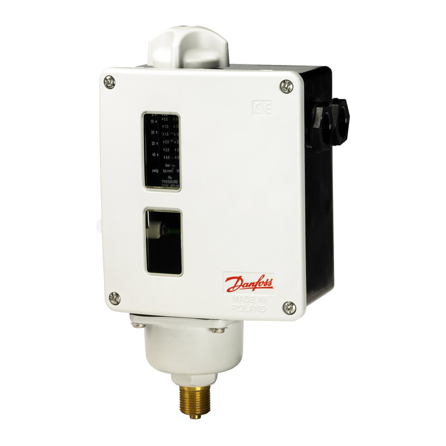
Fail Safe Pressure limitter
Type RT 110
ENGLISH
Technical data
Fail Safe Pressure limiter type RT 110
Stainless Steel as a limiting device of
the boiler - according to EN12953-9.
Electrical fitting:
The RT 110 contact system is designed
according to EN12953-9 requirements
included 250000 switching cycles with
electrical parameters marked on the RT 110
contact system plastic cover.
Using the appliance other than described
AC-1, AC-3, AC-15 or DC-13 modes, may not
be as a limiter.
The RT contact system and any cooperated
external contactors or relays shall, against
the effects of short circuits, be over current
protected with 0,6 safety factor. It means,
that the nominal current of the device, as
stated by the manufacturer, is to be multi-
plied by a safety factor of 0.6.
Example:
Rated load for AC15 is 1A.
Safety factor is 0,6 in consequence,
fuse = 1A x 0,6 = 0,6A or less.
Endurance of any external contactors and
relays must be according to EN12953-9,
which means 250000 switching cycles
under conditions similar to operating
conditions and be capable of a mechani-
cal life time of 3000000 switching cycles.
Conditions similar to operating conditions
covers chemical and climatic influences as
well as electrical and mechanical stresses.
In addition, contactors must fulfil EN60947
and relays must fulfil EN60255.
Wires for connecting the RT 110 must be
according to the specifications of
prEN 50156-1 standard and may not de-
crease electrical safety or IP-protection of
the appliance. After connection to the wir-
ing use cable ties or similar to protect the
wires of slippingout of the screw-terminals
in order to prevent unintended movement
of the wires.
Generally, when there is no pressure
working on the appliance:
– Terminal 1 is C (common one)
– Terminal 2 is NC (terminal 2 is normally
connected to common terminal 1)
– Terminal 4 is NO (terminal 4 is normally
opened with common terminal 1)
© Danfoss | DCS (jmn) | 2015.12
NOTICE, there are two different ways of
working for pressure limiter: one as a
pressure limiter for rising and another one
as a pressure limiter for falling.
For identification, there is adequate
description on the bottom of housing (see
below examples).
For rising:
When the pressure rise up and achieve set-
ting point, contacts change:
– 1-2 disconnection
– 1-4 connection
When the pressure fall down below setting
point + diff erential value, contacts change
back:
– 1-2 connection
– 1-4 disconnection
For rising:
When the pressure fall down and achieve
setting point, contacts change:
– 1-2 connection
– 1-4 disconnection
When the pressure rise up above setting
point + diff erential value, contacts change
back:
– 1-2 disconnection
– 1-4 connection
Locking/reset mechanism:
Since the pressure limiter type RT 110 has
no lockout with manual resetting, this
functions must be realized externally as
a part of a safety logic e.g. by external
contactors and/ or relays which then are to
be used according to the requirements of
prEN50156-1 standard for safety relevant
hardware. External closure must not be
interlocked, while loss of auxiliary energy
must lead to a closure.
Resetting must not be automated, it has to
be performed manually. Resetting on fault
must lead to a repeated closure.
When RT limits, for rising or falling applica-
tion, the external safety logic must change
to the fail safe position.
Pressure fitting:
In order to prevent malfunction of the
limiter, the pressure installation must be
according to Danfoss Instruction 017R9315
and below description harmonized with
the requirements of EN12953-9.
For safety purpose, accessory 060-333366
and 060-007166 can not be used with the
limiter!
Steam boilers:
Connecting pipes for the limiter shall be
connected to the steam space of the boiler
and if necessary, the limiter shall be
protected from the steam temperature by
a water seal. If an insolating valve is fitted
on the connection pipe, an insulation valve
shall be installed which shall be capable of
being locked.
Fully fl ooded hot water generators:
The limiter shall be connected to the supply
pipe before the fi rst shut-off valve.
The limiter body shall be installed verti-
cally so that dirt does not enter the limiter.
If there is the possibility of sludge build-up
in the connection pipe it shall be possible
to purge the pipe. Such purging must
not remove the water seal or introduce
dirt into the water seal. In addition, the
connection pipe and its boiler connection
must be designed for cleaning and inspec-
tion and have a clear bore of at least:
1. where pipe supplies only the imiter:
ø8mm- if pipe is less than 1m long.
ø15mm - if pipe is greater than 1m long.
2. where pipe supplies the limiter in
addition to other limiters:
ø20mm - for all lengths of pipes.
Provision shall be made for functional test-
ing of the limiter. The result of the test shall
be clearly indicated to the boiler operator.
Setting:
RT 110 with factory setting:
RT 110 with factory setting are secured by
manufacturers sealing. Setting screw and
plastic cover with window can not be turn-
ed or removed without breaking the seal.
Connection of wires to the RT 110 contact
system must be performed after removing
the sealing and plastic cover, without any
changing of the setting value. In order to
protect RT device against changing chang-
ing of the setting, after wiring, a seal must
be applied by the customer.
RT 110 without factory setting:
The same conditions as in the RT 110 with
factory setting paragraph. Checking
accuracy of the setting by the customer
must be done with calibrated pressure
gauge. Scale can be used only as an indica-
tion of the pressure setting.
Adjusting the appliance to more than 3
bar or less than 0.05 bar will cause faulty
operation to the appliance and safe
function is not reliable any more!
IC.PI.P10.C3.52 | 520B6875 | 1
Advertisement

Related Manuals for Danfoss RT 110


Summary of Contents for Danfoss RT 110
- Page 1 RT 110 without factory setting: of the wires. Resetting must not be automated, it has to The same conditions as in the RT 110 with be performed manually. Resetting on fault factory setting paragraph. Checking Generally, when there is no pressure must lead to a repeated closure.
- Page 2 EN60947og relæer kravene i EN60255. relæer, som så skal anvendes på sikker- ningerne er forbundet. Ledninger til tilslutning af RT 110 skal være hedsrelevant udstyr i henhold til kravene i udformet i henhold til specifi kationerne i EN50156-1.
- Page 3 EN60255 erfüllen. Die Werkseinstellung des RT110 ist durch Schützen und/oder Relais, die dann gemäß Die Anschlussdrähte für RT 110 müssen ein herstellerseitiges Siegel gesichert. den Anforderungen der prEN50156-1 für gem. den Spezifi kationen der prEN50156-1...
- Page 4 RT 110 avec réglage en usine: relais doivent satisfaire respectivement aux être exécutée extérieurement - et donc faire Le RT 110 avec réglage en usine est sécurisé exigences des normes EN60947 et EN60255. par un plombage du fabricant. Le bouton de partie d’un dispositif logique de sécurité...