Advertisement
Quick Links
T
ECHNICAL INFORMATION
Model No.
Description
C
ONCEPT AND MAIN APPLICATIONS
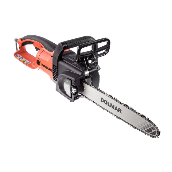
These electric chain saws have been developed as the up-graded
successors to the current ES-2035A series models.
Designed with the concept of "Easy Operation and Maintenance",
and feature the following main advantages;
Toolless blade change and adjustment
Handles with soft grip for more comfort and control
ES-2135A and ES-2140A for Germany feature PRO 91 guide bar
for professional use.
S
pecification
Voltage (V)
110
120
220
230
240
Model No.
Chain speed per sec:
m/s (m/min) [ft/min]
Type
Standard
guide bar
Size: mm (")
Type
Chain blade
Pitch
Chain brake
Chain oil tank
capacity: ml
Automatic chain oiling
Double insulation
Power supply cord:
m (ft)
Net weight: kg (lbs)
S
tandard equipment
Chain blade ........................ 1 pc
Guide bar ........................... 1 pc
Guide bar cover ................. 1 pc
Hook complete .................. 1 pc
Note: The standard equipment for the tool shown above may differ by country.
O
ptional accessories
Chain blade (91VG) (300/ 350/ 400/ 450mm)
Guide bar (DOUBLE GUARD: 91VG) (300/ 350/ 400/ 450mm)/ (PRO 91/ 91VG) (350/ 400mm)
Chain oil
ES-2130A/ ES-2135A/ ES-2140A/ ES-2145A
Chain Saws 300mm(12")/ 350mm(14")/
400mm(16")/ 450mm (18")
Current (A)
Cycle (Hz)
15
50/ 60
14.5
50/ 60
8.6
50/ 60
9.2
50/ 60
8.8
50/ 60
DOLMAR
ES-2130A
ES-2135A
DOUBLE GUARD: 91VG
300 (12)
350 (14)
91VG-46E
91VG-52E
UK: 10 (32.8), European countries except for UK: 5 (16.4)
Continuous Rating (W)
Input
1,570
1,650
1,800
2,000
2,000
International
ES-2140A
ES-2145A
13.3 (800) [2,600]
450 (18)
400 (16)
91VG-62E
91VG-56E
3/8"
Electric brake
140
Yes
Yes
Other countries: 0.3 (0.98)
4.4 (9.7)
[Without guide bar and chain blade]
PRODUCT
W
H
L
*Dimensions: mm (")
Length (L)
492 (19-3/8)
Width (W)
201 (7-7/8)
Height (H)
220 (8-5/8)
*Dimensions: without guide bar.
Max. Output (W)
Output
900
1,800
900
1,800
1,000
2,200
1,100
2,200
1,100
2,200
Germany
DOLMAR
-Professional
ES-2135A
ES-2140A
PRO 91: 91VG
350 (14)
400 (16)
91VG-52E
91VG-56E
P 1 / 7
Advertisement

Summary of Contents for Dolmar ES-2135A
- Page 1 Toolless blade change and adjustment Handles with soft grip for more comfort and control *Dimensions: mm (") ES-2135A and ES-2140A for Germany feature PRO 91 guide bar Length (L) 492 (19-3/8) for professional use.
-
Page 2: Necessary Repairing Tools
P 2 / 7 epair CAUTION: Remove the chain blade, guide bar from the machine for safety before repair/ maintenance ! Make sure that chain oil is removed from oil tank ! [1] NECESSARY REPAIRING TOOLS Code No. Description Use for 1R005 Retaining ring pliers RT-2N Removing Compression spring 9... - Page 3 P 3 / 7 epair [3] -2. Lubricating Mechanism, Front Hand Guard Fig. 3 DISASSEMBLING 1) Remove Sprocket cover. Front handle 2) Remove six Screws that fasten Spike bumper and Front handle. (Fig. 3) 3) Turn the machine upside down. Remove Front handle while pulling in the direction of the arrow.
- Page 4 P 4 / 7 epair [3] -3. Armature, Crank, Straight Bevel Gears 14 and 43 (cont.) 5) Lever off Bearing housing using two 1R263 or slotted screwdrivers. (Fig. 8) 6) Remove Ball bearing 606ZZ and Cam using 1R269. By removing E ring 10, Straight bevel gear 43 can be removed.
-
Page 5: Ircuit Diagram
P 5 / 7 epair [3] -4. Kickback Brake Section Including Brake Drum (Sprocket) (cont.) 8) Insert one jaw of 1R005 into the hole of Link plate complete and the other Fig. 13 in an appropriate portion of Compression spring 9 as illustrated in Fig. 13. By closing the jaws of 1R005, Compression spring 9 can be removed. -
Page 6: Wiring Diagram
P 6 / 7 iring diagram Fig. D-2 Kickback switch Fix Lead wires of Kickback switch with this Lead wire holder. Motor housing Fig. D-3 Motor housing Fix Lead wires with these Lead wire holders. Route Lead wires through these ribs. Lead wire of Controller Field lead wire... - Page 7 P 7 / 7 iring diagram Fig. D-4 Fix the following Lead wires with Lead wire Lead wire holder holders under Main switch: Connect Lead unit (orange) yellow one to No.1 terminal of Main switch as illustrated below. orange one to No.2 terminal of Main switch red one to No.4 terminal of Main switch to No.2 terminal of Main switch Important:...


