Table of Contents
Advertisement
Quick Links
Specifications .................................................................................................................................................... 3
Performance Specifications ............................................................................................................................... 4
Electrical Parts List ............................................................................................................................................ 5
Printed Circuit Boards ........................................................................................................................................ 8
Wiring Diagram ................................................................................................................................................ 10
Voltage Chart ................................................................................................................................................... 11
IC Block Diagrams & IC Pins Description ........................................................................................................ 13
Block Diagram .................................................................................................................................................. 16
Exploded Drawing and Mechanical Parts List ................................................................................................. 17
Schematic Diagram .......................................................................................................................................... 19
Many electrical and mechanical parts in this chassis have special safety characteristics.
These safety characteristics often pass unnoticed and the protection afforded by them cannot
necessarily be obtained by using replacement components rated for higher voltage, wattage, etc.
Replacement parts that have these special safety characteristics are identified in this manual
and its supplements; electrical components having such features are identified by
schematic diagram and the parts list.
Before replacing any of these components, read the parts list in this manual carefully.
The use of substitute replacement parts that do not have the same safety characteristics as
specified in the parts list may create shock, fire or other hazards.
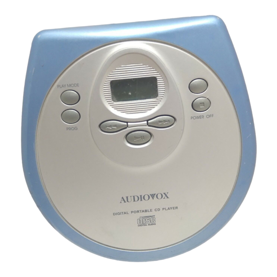
COMPACT DISC COMPACT PLAYER
PRODUCT SAFETY NOTICE
DM8900-00
CONTENTS
Page
in the
Advertisement
Table of Contents

Related Manuals for Audiovox DM8900-00


Summary of Contents for Audiovox DM8900-00
-
Page 1: Table Of Contents
COMPACT DISC COMPACT PLAYER DM8900-00 CONTENTS Page Specifications ..............................3 Performance Specifications ..........................4 Electrical Parts List ............................5 Printed Circuit Boards ............................8 Wiring Diagram ..............................10 Voltage Chart ..............................11 IC Block Diagrams & IC Pins Description ......................13 Block Diagram .............................. -
Page 2: Specifications
SPECIFICATIONS General Compact disc digital audio system • Digital filter two-time oversampling • Three-spot optical pick up Output (at 1kHz 0dB Level) Line output (stereo minijack) Ω Output level 0.4V(Rms) at 47K at 1kHz Headphones/earphone (stereo minijack) Ω Ω 15 mW + 15 mW at 16 to 32 Power requirements 2 size AA (LR6 or SUM-3) alkaline batteries, or DC IN 6V,... -
Page 3: Performance Specifications
PERFROMANCE SPECIFICATIONS GENERAL TEST CONDITION Power Supply : AC - DC Adaptor 100V: 6V DC 60Hz Battery:3V (AA x 2) 120V: 6V DC 60Hz 230V: 6V DC 50Hz Lineout Load : 47Kohm Headphone Output : 16ohm or 32ohm Reference Output : 5mW Input Signal Source : CBS SONY YED7 (PTD-001) SONY... -
Page 4: Electrical Parts List
ELECTRICAL PARTS LIST Ref. No. Description Mfr's Part No. Qty. MAIN BOARD PCB CDM52-01-01 122x199x0.8mm/2 (FR4) 033-0CDM52-100 DOUBEL-SIDED CONTROL BOARD PCB CDM52C-01-02 125x176x1.0mm/12 (94HB) 033-CDM52C-100 FLASH GOLD RESISTORS R604,605 CHIP RESISTOR 33 ohm +-5% 1/10W (0805/2012) 001-333050-010 R320,609,245 CHIP RESISTOR 10 ohm +-5% 1/16W (0603/1608) 001-310052-016 R601 CHIP RESISTOR 100 ohm +-5% 1/16W (0603/1608) - Page 5 ELECTRICAL PARTS LIST - CONTINUED Ref. No. Description Mfr's Part No. Qty. C609,610,139,134,120, CHIP CAP 0.1 uF/16V +80-20% (0603/1608) 003-510482-016 217,220,201,205,506,501, (MCH182F104ZK/GRM39Y5V104Z16PT) 601,302,320,116,215,228, 229,509,126,504 C114,125,130,313,314 CHIP CAP 0.0022 uF/50V +-10% (0603/1608) 003-522212-050 (UMK107B222KZ-TM) C221 CHIP CAP 0.22 uF/16V +80-20% (0603/1608) 003-522482-016 C605,124 CHIP CAP 0.0033 uF/50V +-10% (0603/1608)
- Page 6 ELECTRICAL PARTS LIST - CONTINUED Ref. No. Description Mfr's Part No. Qty. D607 DIODE RB100A/1S40 011-000100-000 D601,702 RECTIFIER IN-4001B 011-024001-000 D301,501 CHIP DIODE DAN222 011-040222-001 INDUCTORS L601 IFT R0002-CY68-950M-825549 10mm 012-825549-010 L602 INDUCTOR 10uH +-10% RL4055-100K 5x7.5mm 018-010015-200 w/UL TUBE =018-010015-000 L603 INDUCTOR 33 uH +-10% RL4055-330K 018-010336-200...
-
Page 7: Printed Circuit Boards
PRINTED CIRCUIT BOARDS MAIN BOARD CDM52-01-01 CN501 C218 D601 C219 C508 C230 L304 C306 VR301 X201 C552 L301 L303 C316 C301 C319 L302 C108 C332 VR101 C334 C335 C214 CDM52 ( REV-1) 033-0CDM52-100 L201 08-MAY-2000 C115 C603 TOP VIEW... - Page 8 MAIN BOARD CDM52-01-01 TP501 D701 Q701 R703 IC501 C550 R702 TAP501 R701 IC701 C704 TAP503 R501 C506 TAP502 R511 C805 R514 R250 C701 C808 R220 C220 R311 R218 R223 R219 R222 R231 R314 C229 R232 Q305 R310 C804 R313 C227 R111 C216 TP103...
-
Page 9: Wiring Diagram
WIRING DIAGRAM... -
Page 10: Voltage Chart
VOLTAGE CHART THE MEASURED VALUE IS DC VOLTAGE UNIT:V TEST CONDITION: CD PLAY IC501 (BU34581-5G) PIN'S NUMBER 1.49 PIN'S NUMBER 1.49 1.49 1.54 1.49 1.49 PIN'S NUMBER 3.11 3.10 3.10 3.10 3.10 PIN'S NUMBER 3.10 3.10 3.06 0.05 PIN'S NUMBER 3.05 3.02 0.15... - Page 11 VOLTAGE CHART - CONTINUED IC301 (BA3579FS) PIN'S NUMBER 1.48 1.47 1.39 0.70 PIN'S NUMBER 1.54 0.70 1.54 1.54 0.69 1.00 1.00 3.11 IC101 (BA6387K) PIN'S NUMBER 1.56 0.97 1.18 1.49 2.21 2.32 PIN'S NUMBER 1.15 2.21 3.05 1.54 PIN'S NUMBER 1.58 1.77 1.08...
-
Page 12: Ic Block Diagrams & Ic Pins Description
IC BLOCK DIAGRAMS & IC PINS DESCRIPTION IC301 BA3579FS PVCC AVDD 47 k 100 p 47 k AVDD PVCC IC201 BU9526KS C1FX SYSCK C2FX C2F3 AVDD AVDD C2F4 DFDCK WINDOW DFDIN PLLSW DFLRCK DGND3 ADPFI AVDD2 ADPFO LOUT AGND 16K SRAM RVCO ROUT AGND2... - Page 13 IC501 BU34581-5G CPUO2A TEST RESET OSC1 CLOCK RESET PC STACK 8 PC INC OSCO3A 512x4 OSC2 SYSTEM INSTRUCTION 16384x8 DECODER FLAG INTERRUPT CONTROL FLAG U-BUS L-BUS IC101 BA6387K µ DET BLOCK PS PL BL BS MIRR 44.7k 44.7k DEFECT 0.6V SCRATCH HOLD BLOCK CONTROL...
- Page 14 IC601 BA5901K PINS DESCRIPTION Pin No. Pin Name Function BSEN Battery voltage monitor terminal BATT Battery power supply input terminal RESET Cassette detection output terminal DEAD Dead-time setting terminal Booster transistor drive terminal Error amplifier output terminal Error amplifier input terminal SPRT Short-circuit protection setting terminal Triangular wave output terminal...
-
Page 15: Block Diagram
BLOCK DIAGRAM... -
Page 16: Exploded Drawing And Mechanical Parts List
EXPLODED DRAWING & MECHANICAL PARTS LIST Description Ref. No. Mfr's Part No. Qty. DISPLAY PLATE, 0.5mm THK, TRANSPARENT PVC, w/o PRINTING 650-890003-000 CD DOOR, MOLD C.GR 2C (ABS), w/SPY & PNT 500-890001-xxx MIDDLE CAB (w/LOCK), MOLD D.GR (1524A), (ABS) CAV:2, 500-890302-000 (SONY/SANYO/SAMSUNG/THOMSON) CD DOOR SPRING, DIA:0.7mm SPRING WIRE (NICKEL PLATED) - Page 17 EXPLODED DRAWING...
-
Page 18: Schematic Diagram
SCHEMATIC DIAGRAM NOTES: 1. All resistance values are indicated in “ohms” (k=1000 ohms. M=1000 kohms). 2. All capacitance values are indicated in “µF” (p=10 µF). - Page 19 NOTES: ALCO ELECTRONICS LTD APRIL, 2002 808-890000-020 Printed in Hong Kong...