Table of Contents
Advertisement
Quick Links
Perkins 700 Series
Models UA, UB and UC
WORKSHOP MANUAL
Four cylinder naturally aspirated and turbocharged
diesel engines
Publication TPD 1392E, Issue 3.
© Proprietary information of Perkins Engines Company Limited, all rights reserved.
The information is correct at the time of print.
Published in February 2002 by Technical Publications.
Perkins Engines Company Limited, Peterborough PE1 5NA, England.
i
This document has been printed from SPI². Not for Resale
Advertisement
Table of Contents

Related Manuals for Perkins UA


Summary of Contents for Perkins UA
- Page 1 Four cylinder naturally aspirated and turbocharged diesel engines Publication TPD 1392E, Issue 3. © Proprietary information of Perkins Engines Company Limited, all rights reserved. The information is correct at the time of print. Published in February 2002 by Technical Publications.
- Page 2 This publication is written in Perkins Approved Clear English Chapters 1 General information 2 Specifications 3 Cylinder head assembly 4 Piston and connecting rod assemblies 5 Crankshaft assembly 6 Timing case and drive assembly 7 Cylinder block assembly 8 Engine timing...
-
Page 3: Table Of Contents
700 Series Contents 1 General information Introduction ..................1 Engine views - Naturally aspirated engine ............ 3 Engine views - Turbocharged engine . - Page 4 700 Series 3 Cylinder head assembly Rocker cover Operation 3-1 To remove and to fit ............35 Rocker assembly (latest engines) Operation 3-2 To remove and to fit ...
- Page 5 700 Series Valve seats Operation 3-16 To correct ............... 52 Valve seat insert Operation 3-17 To fit ................53 Cylinder head Operation 3-18 To check the distortion of the lower face ..
- Page 6 700 Series 5 Crankshaft assembly Crankshaft pulley Operation 5-1 To remove and to fit ............77 Operation 5-2 To fit a wear sleeve ............. 79 Rear oil seal Operation 5-3 To remove ...
- Page 7 700 Series 6 Timing case and drive assembly Tamper proof screws Operation 6-1 To remove and to fit ............. 95 Timing case Operation 6-2 To remove and to fit ...
- Page 8 Engine breather assembly Operation 9-3 To renew (UA and UB engines) ..........126 Operation 9-4 To renew (Early UC engines) ..........127 Operation 9-5 To renew (Latest UC engines) ...
- Page 9 700 Series 10 Lubrication system Oil filter canister Operation 10-1 To renew ............... 131 Engine lubricating oil Operation 10-2 To renew ..
- Page 10 700 Series Fuel lift pump Operation 11-6 To remove and to fit ............148 Operation 11-7 To test ................149 Fuel injection pump Operation 11-8 To remove and to fit ..
- Page 11 700 Series 13 Flywheel and housing Flywheel Operation 13-1 To remove and to fit ............173 Operation 13-2 To inspect ..............174 Starter ring Operation 13-3 To remove and to fit .
- Page 12 This page is intentionally blank This document has been printed from SPI². Not for Resale...
-
Page 13: General Information
Workshop Manual. The two publications should be used together. The engines referred to in this manual are the UA (3,0 litre - direct injection), the UB (2,6 litre - indirect injection) and the UC (3,0 litre - turbocharged direct injection). - Page 14 700 Series The 3,0 litre versions are, water cooled, naturally aspirated or turbocharged, four cylinder diesel engine with direct injection. They have been specifically designed for industrial and agricultural applications. The 2,6 litre version, is a water cooled, naturally aspirated, four cylinder diesel engine with indirect injection. It has been specifically designed for fork-lift truck applications.
-
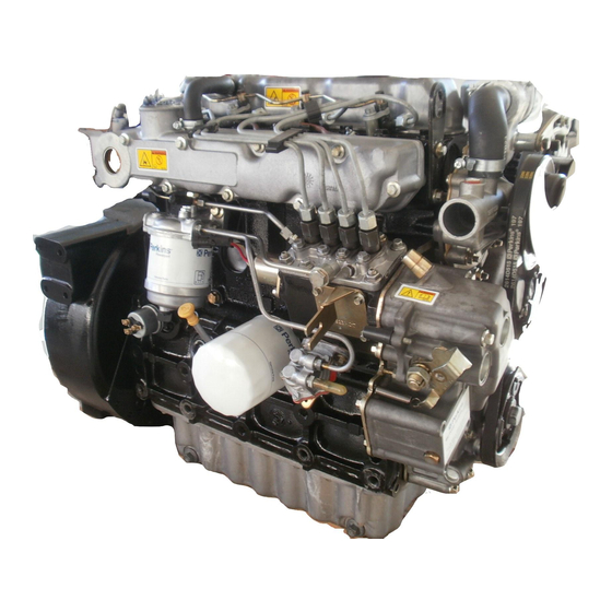
Page 15: Engine Views - Naturally Aspirated Engine
700 Series Engine views - Naturally aspirated engine Workshop Manual, TPD 1392E, issue 3 This document has been printed from SPI². Not for Resale... -
Page 16: Engine Views - Turbocharged Engine
700 Series Engine views - Turbocharged engine Workshop Manual, TPD 1392E, issue 3 This document has been printed from SPI². Not for Resale... -
Page 17: Engine I.d. Location
700 Series Engine I.D. location The engine number is stamped on a label (A1) that is located on the right rear side of the engine. It consists of the following: Abbreviations and codes Engine build list numbering system. The engine parts list numbering system is defined as follows: Code Example 80862... -
Page 18: Safety Precautions
700 Series Safety precautions These safety precautions are important. You must refer also to the local regulations in the country of use. Some items only refer to specific applications. l These safety precautions are important. You must refer also to the local regulations in the country of use. Some items only apply to specific applications. - Page 19 Some components are not waterproof and should not be washed with a high-pressure water jet or steam. l Fit only genuine Perkins parts. Workshop Manual, TPD 1392E, issue 3 This document has been printed from SPI². Not for Resale...
-
Page 20: Viton Seals
700 Series Viton seals Some seals used in engines and in components fitted to engines are made of Viton. Viton is used by many manufacturers and is a safe material under normal conditions of operation. If Viton is burned, a product of this burnt material is an acid that is extremely dangerous. Never allow this burnt material to come into contact with the skin or with the eyes. -
Page 21: Engine Lift Equipment
700 Series Engine lift equipment Caution: If the sump contains engine lubricating oil and the engine is tilted to an extreme angle or turned onto its side or end faces, lubricating oil can enter the closed breather system, pass into the induction manifold and the cylinder bores. -
Page 22: Powerpart Consumable Products
700 Series POWERPART consumable products Perkins have made available the products recommended below in order to assist in the correct operation, service and maintenance of your engine and your machine. The instructions for the use of each product are given on the outside of each container. These products are available from your Perkins distributor. - Page 23 700 Series POWERPART Red rubber grease Provides lubrication for the fitting of “O” rings. Part number 21820221. POWERPART Retainer (high strength) To retain components that have an interference fit. Part number 21820638. POWERPART Retainer (oil tolerant) To retain components that have a transition fit. Part number 21820603. POWERPART Safety cleaner General cleaner in an aerosol container.
- Page 24 This page is intentionally blank This document has been printed from SPI². Not for Resale...
-
Page 25: Specifications
Compression ratio UA and UC engines ................17.5:1 UB engines ..................22.0:1 Combustion system UA and UC engines ... -
Page 26: Data And Dimensions
Minimum permissible thickness after cylinder head has been machined: UA and UC engines ..............79,8 mm (3.142 in) UB engines - the cylinder head for this engine must not be machined, see Caution on page 54. - Page 27 Service limit: UA and UC engines ..............0,98 mm (0.039 in) UB engines ................0,93 mm (0.037 in) Overall length of valve .
- Page 28 700 Series Valve springs, tappets, and rocker levers Valve springs Fitted length ................32,0 mm (1.26 in) Load at fitted length ...
- Page 29 Dimensions of a recess for a valve seat insert Inlet - UA and UC engines A1 ..............Radius 0,38 mm (0.015 in) maximum A2 ..
- Page 30 700 Series Dimensions for a valve seat insert tool UA and UC engines Inlet A1..................1,5 mm (0.06 in) A2...
- Page 31 700 Series UB engines Inlet A1 ..................1,5 mm (0.06 in) A2 ..................19,0 mm (0.7 in) A3 ..
- Page 32 Type: UA engines ..............Re-entrant combustion bowl UB engines ............... Flat top with recess for valves UC engines ...
- Page 33 Type: UA and UB ............... Steel back, aluminium / tin face UC ...............Steel back, copper / lead face Width ..
- Page 34 Crankshaft heat treatment UA and UB ..............Induction hardened journals UC............Induction hardened journals and fillet radii...
-
Page 35: Timing Case And Drive Assembly
700 Series Timing case and drive assembly Camshaft Diameter of number 1 camshaft journals - camshaft numbers: U3141D143 ............47,982/47,992 mm (1.8891/1.8894 in) 3141D091 ... - Page 36 Surface finish size, silicon carbide base hone UA and UC engines ..............97,507 mm (3.8388 in) UB engines ...............91,507 mm (3.6026 in) Grade of surface finish.
- Page 37 Cylinder block - UB engines (A) UB ENGINES 45° x 45° TYPICAL 0, 2 0,010 TYPICAL 0,020 0, 0 3 /100 Y-Z Cylinder block - UA and UC engines (B) UA AND UC ENGINES x 45° TYPICAL 0, 2 97,525 TYPICAL Ø 0,010 97,500...
- Page 38 700 Series Timing data Fuel injection pump Make ..............Zexel PFR-KX in-line cassette type Direction of rotation.............Clockwise from drive end Fuel pump code letters ...
-
Page 39: Lubrication System
700 Series Lubrication system Lubricating oil pump Type ................Differential rotor, gear driven Number of lobes .............. Inner rotor 4, outer rotor 5 Maximum permissible clearance of outer rotor to pump body. -
Page 40: Fuel System
Fuel pump code letters: UA engines ................AJ, BJ, FJ, GJ, HJ, JJ UB engines ................. .CJ, EJ, DJ UC engines ... - Page 41 Current: UA and UC ..............7.0 amperes after 30 seconds UB............... .6.5 amperes after 30 seconds...
-
Page 42: Thread Sealant
700 Series Thread sealant When setscrews or studs are fitted into holes that are tapped through the cylinder block, a suitable sealant must be used to prevent leakage. Micro encapsulated anaerobic sealant (M.E.A.S) fasteners have been introduced instead of jointing compounds or other sealants when the fasteners are fitted in through holes into oil or coolant passages. -
Page 43: Recommended Torque Tensions
700 Series Recommended torque tensions Most of the fasteners referred to in this manual have standard torque tensions that are shown in the table below. Those fasteners that need special torque tensions are listed in separate table. Procedures referred to in this manual will have the torque tensions (standard or special) shown in the text and also listed in the table for special torque tensions. -
Page 44: Cooling System
Angleichung unit to timing case Cylinder block Piston cooling valve, UC engines Breather deflector, UC engines Fuel system Banjo bolt, leak-off pipe, UA and UC engines Nut, leak-off pipe, UB engines Gland nut, atomiser, UB engines Union nut, high-pressure pipe 27,5... -
Page 45: Compression Test Data
700 Series Torque tension Thread Description size lbf ft kgf m Glowplug 15.5 11.5 Connection, glow plug 0,20 Compression test data Tests have shown that many factors affect compression pressures. Battery and starter motor condition, ambient conditions and the type of gauge used can give a wide variation of results for a given engine. It is not possible to give accurate data for compression pressure, but tests have shown that the results should be within 2000/3500 kPa (300/500 lbf/in ) 21,0/35,0 kgf/cm... - Page 46 This page is intentionally blank This document has been printed from SPI². Not for Resale...
-
Page 47: Cylinder Head Assembly
700 Series Cylinder head assembly Rocker cover To remove and to fit Operation 3-1 Special requirements Torque Nm (lbf ft) kgf m Cap nuts 11 (8) 1,1 Cautions: l If the cap nut is over-tightened, the stud and plate assembly for the rocker pedestal may be damaged. l When the crossover pipe is removed, cover the holes in the turbocharger and in the induction manifold to prevent the entry of dirt. -
Page 48: Rocker Assembly (Latest Engines)
700 Series Rocker assembly (latest engines) To remove and to fit Operation 3-2 Special requirements Torque Nm (lbf ft) kgf m Setscrews 9 (7) 0,9 Nuts 22 (16) 2,2 Caution: Before the rocker assembly is fitted, ensure that the oil holes are free of dirt. Check that the push rods fit correctly in the sockets of the tappets. - Page 49 700 Series To fit 1 Fit the rocker shaft, ensure that the hollow pin in the rocker shaft locates in the hole in the front lower bracket. 2 Put the caps in position on the rocker shaft. Ensure that each cap is correctly matched with its lower half. Tighten the nuts starting with the inner nuts and moving outwards.
-
Page 50: Rocker Assembly (Earlier Engines)
700 Series Rocker assembly (earlier engines) To remove and to fit Operation 3-3 Special requirements Torque Nm (lbf ft) kgf m Setscrews 9 (7) 0,9 Nuts 22 (16) 2,2 Caution: Before the rocker assembly is fitted, ensure that the oil holes are free of dirt. Check that the push rods fit correctly in the sockets of the tappets. - Page 51 700 Series To fit 1 Before the rocker assembly is fitted, ensure that the oil holes and are free of dirt. 2 Check that the push rods fit correctly in the sockets of the tappets. 3 Fit the fasteners finger tight. 4 Tighten gradually and evenly, the inner nuts and then the outer nuts to 22 Nm (16 lbf ft) 2,2 kgf m.
-
Page 52: Rocker Shaft (Latest Engines)
700 Series Rocker shaft (latest engines) To dismantle, to inspect and to assemble Operation 3-4 A hollow pin in the rocker shaft locates in the front rocker shaft bracket (see enlarged view below). This pin will align with the oil hole in the cylinder and ensure correct lubrication of the rocker assembly. Protect these holes to ensure that dirt cannot enter. -
Page 53: Rocker Shaft (Earlier Engines)
700 Series Rocker shaft (earlier engines) To dismantle, to inspect and to assemble Operation 3-5 Note: A hardened steel pin (A1) is fitted in the lower part of the front bracket. The purpose of this pin, is to ensure that the bracket is in the correct position on the rocker shaft. The hole in the bracket will align with the oil hole in the cylinder head and ensure correct lubrication of the rocker assembly. -
Page 54: Valve Tip Clearance
700 Series Valve tip clearance To check Operation 3-6 Special requirements Valves rocking Adjust valves No. 4 Cyl 1 and 2 No. 2 Cyl 5 and 6 No. 1 Cyl 7 and 8 No. 3 Cyl 3 and 4 Notes: l Adjust when the engine is cold. -
Page 55: Valve Springs (With Cylinder Head Fitted)
700 Series Valve springs (with cylinder head fitted) To remove and to fit Operation 3-7 Special requirements Special tools Description Part number Description Part number Valve spring compressor 21825666 Stud adaptor 27610016 Warning! Wear eye protection when the valve spring is compressed. Caution: Do not rotate the crankshaft while the valve springs are removed. -
Page 56: Exhaust / Induction Manifolds And Gasket
700 Series Exhaust / induction manifolds and gasket To remove and to fit Operation 3-8 Special requirements Torque Nm (lbf ft) kgf m Early setscrews 22 (16) 2,2 Latest setscrews 18 (13) 1,8 Caution: Some coolant may enter the cylinder bores and the threaded holes for the cylinder head setscrews when the cylinder head is removed. -
Page 57: Cylinder Head Setscrews
700 Series Cylinder head setscrews To remove and to fit Operation 3-9 Special requirements Torque Nm (lbf ft) kgf m 1st torque 70 (52) 7,1 2nd torque 100 (74) 10,2 Tighten and re-check torque. Release the setscrews in reverse of the sequence shown. Note: Lubricate threads and under flange of the setscrews. -
Page 58: Cylinder Head Gasket
700 Series Cylinder head gasket To remove and to fit Operation 3-10 Note: Two dowels are fitted to the cylinder block to ensure that the cylinder head gasket and the cylinder head remain in the correct position when the setscrews are tightened. Caution: There is a rubber grommet (A1) fitted in the cylinder head gasket for UB engines only. -
Page 59: Valve And Valve Springs
700 Series Valve and valve springs To remove and to fit Operation 3-11 Special requirements Special tools Description Part number Valve spring compressor 27610020 Warning! Wear eye protection during this operation. Cautions: l Ensure that the valve springs are compressed squarely or the valve stem can be damaged. l Genuine valve stem seals must be used. -
Page 60: Valve Stem
700 Series Valve stem To inspect Operation 3-12 Special requirements Diameter mm (in) 6,970-6,985 Inlet valve (0.2704-0.2750) 6,945-6,960 Exhaust valve (0.2734-0.2740) Warning! Wear eye protection during this operation. Cautions: l Ensure that the valve springs are compressed squarely or the valve stem can be damaged. l Genuine valve stem seals must be used. -
Page 61: Valve Depth
700 Series Valve depth To check Operation 3-13 Special requirements Special tools Description Part number Description Part number Gauge, valve depth 21825496 Dial gauge 21825617 For valve depth specifications refer to the relevant Data and dimensions for "Inlet and exhaust valves" on page 15. Workshop Manual, TPD 1392E, issue 3 This document has been printed from SPI². -
Page 62: Valve Guides
700 Series Valve guides To check Operation 3-14 Special requirements Special tools Maximum permissible clearance mm (in) Description Part number Inlet valve 0,24 (0.009) Dial test indicator 21825617 Exhaust valve 0,28 (0.011) Notes: l A new valve must be used to check the guide. l There must be a valve lift of 15 mm. - Page 63 700 Series To remove and to fit Operation 3-15 Special requirements Special tools Description Part number Description Part number Valve guide remover/replacer 21825478 Adaptor (replacer) 27610017 Spacer 21825480 Adaptor (remover) 27610019 Notes: l The internal recess in the valve guide must be towards the tool. l Service valve guides are supplied with the internal diameter unfinished and must be reamed or machined to the correct diameter.
-
Page 64: Valve Seats
700 Series Valve seats To correct Operation 3-16 Special requirements Special tools Description Part number Valve seat cutting tool - kit 21825938 Note: If a valve seat has become too damaged or too worn to correct, a valve seat insert can be fitted, see Operation 3-17. -
Page 65: Valve Seat Insert
4 Measure the depth of the recess in two places 90° apart. The correct depths are: UA and UC engines: 8,35/8,55 mm (0.329/0.337 in) UB engines: 8,20/8,40 mm (0.320/0.330 in) 5 If the depth of the recess has been reduced, surface grind the bottom face of the insert by an equivalent amount. -
Page 66: Cylinder Head
If there are cracks in these areas, the cylinder head assembly should be renewed. 6 The bottom face of the cylinder head for only UA and UC engines can be machined if, there is distortion, deep scratches or the valve depths are below the service limit. -
Page 67: Piston And Connecting Rod Assemblies
700 Series Piston and connecting rod assemblies Big end bearing and cap To remove and to fit the early type Operation 4-1 Special requirements Torque Nm (lbf ft) kgf m Big end nuts 54 (40) 5,5 Notes: l Identify connecting rod to cylinders and piston when dismantled. l Ensure that when the rods are fitted an axial play is provided. - Page 68 700 Series The letter that is engraved on the right side of the connecting rod is the manufacturer’s reference number. The part number shown on the connecting rod should always be towards the front of the engine. Location tags for the shell bearings will always be on the fuel pump side of the engine. Service operations Remove the sump, see Operation 10-4 or Operation 10-5.
- Page 69 700 Series The letter that is engraved on the right side of the connecting rod is the manufacturer’s reference number. The part number shown on the connecting rod should always be towards the front of the engine. Service operations Remove the sump, see Operation 10-4 or Operation 10-5. Remove the strainer pipe, see Operation 10-6.
-
Page 70: Piston And Connecting Rod
(ie) 1 and 4 or 2 and 3, it is recommended that the complete set of pistons are renewed. This will prevent engine vibration due to out- of-balance forces. UA & UC ENGINES UB ENGINES Continued Workshop Manual, TPD 1392E, issue 3 This document has been printed from SPI². - Page 71 700 Series Service operations Remove the cylinder head, see Chapter 3, Cylinder head assembly. Remove the big end bearing nuts, see Operation 4-1. Workshop Manual, TPD 1392E, issue 3 This document has been printed from SPI². Not for Resale...
- Page 72 700 Series To fit the early type Operation 4-4 Special requirements Special tools Torque Nm (lbf ft) kgf m Description Part number Big end nuts 54 (40) 5,5 Piston ring compressor 21825491 Cautions: l The correct piston height must be maintained in service to prevent damage to the pistons and valves, and ensure that the engine conforms to emissions legislation.
- Page 73 700 Series To dismantle and to assemble the latest type (fractured split connecting rods)Operation 4-5 Cautions: l The torx screws must only be used once. l When the big end cap is removed, a small amount of metal may fall away from around the torx screw holes (maximum particle size is 1 x 3 x 5 mm (0.39 x 0.117 x 0.195 in).
- Page 74 (ie) 1 and 4 or 2 and 3, it is recommended that the complete set of pistons are renewed. This will prevent engine vibration due to out- of-balance forces. UA & UC ENGINES UB ENGINES U1149 Service operations Remove the cylinder head, see Chapter 3, Cylinder head assembly.
- Page 75 700 Series To fit the latest type (fractured split connecting rods) Operation 4-6 Special requirements Special tools Torque Nm (lbf ft) kgf m Description Part number Big end torx screw 54 (40) 5,5 Piston ring compressor 21825491 Cautions: l The correct piston height must be maintained in service to prevent damage to the pistons and valves, and ensure that the engine conforms to emissions legislation.
-
Page 76: Piston And Piston Rings
700 Series Piston and piston rings To remove and to fit Operation 4-7 Any letters or markings on a surface of a ring will always be on the top face (facing upwards). Caution: Only expand the ring gaps enough to ensure that the ends of the rings do not damage the piston when the ring is removed or put into position. - Page 77 700 Series To inspect Operation 4-8 1 Fit new piston rings in the grooves in the piston and check for wear of the grooves with feeler gauges. 2 Compare the piston ring clearance in the groove to that given for new components in the relevant Data and dimensions for "Pistons and connecting rods"...
-
Page 78: Piston Rings
700 Series Piston rings To inspect Operation 4-9 Piston ring If the piston ring is worn or damaged, renew it. Piston ring gap Clean all carbon from the top of the cylinder bores. Fit each of the piston rings in the top unworn part of the cylinder bore and measure the ring gap with feeler gauges. -
Page 79: Connecting Rod
700 Series Connecting rod To check for bend and to inspect Operation 4-10 Cautions: l Do not use a letter stamp to mark the connecting rod. The new letter must be engraved onto the big-end of the connecting rod. l If the original piston is used, ensure that it is assembled to the correct connecting rod and is used in the original cylinder. - Page 80 700 Series Note: The large and small end bores must be square and parallel with each other within the limits of +/- 0,20 mm (0.0007 in) measured 130 mm (5.1 in) each side of the connecting rod axis on a test mandrel (A). To check the connecting rod for bend In service, initially, three pistons of different heights (High, Nominal and Low) were supplied and one connecting rod.
- Page 81 700 Series The correct piston height is important to ensure that the piston does not contact the cylinder head and to ensure the efficient combustion of the fuel. If the crankshaft or the cylinder block is to be renewed, it may be necessary to change the grade of the connecting rods.
- Page 82 700 Series To check length and to inspect Operation 4-11 Cautions: l The big-end bolts are fitted to the connecting rod by a special process and must not be removed. As the connecting rod, and the bolts will be damaged. l It is important that the piston does not contact the cylinder head.
- Page 83 700 Series If the grade letter on the connecting rod cannot be seen, the length can be checked by the measurement of the dimension on each side of the connecting rod. Measure as close as possible to the connecting rod. Calculate the average of the two measurements to find the length of the connecting rod.
-
Page 84: Small End Bush
For further information refer to the Technical Service Department, Perkins Engines, Peterborough, England. l Do not use a letter stamp to mark the connecting rod. The new letter must be engraved onto the big-end of the connecting rod. -
Page 85: Piston Height Above The Cylinder Block
700 Series Piston height above the cylinder block To check Operation 4-13 Special requirements Special tools Description Part number Description Part number Dial gauge Piston height tool 21825496 21825617 (for use with the piston height tool) Caution: The correct piston height must be maintained in service to prevent damage to the pistons and valves and ensure that the engine conforms to emissions legislation. -
Page 86: Piston Cooling Jets (Uc Engines)
700 Series Piston cooling jets (UC engines) To remove, and to fit Operation 4-14 Special requirements Torque Nm (lbf ft) kgf m Banjo bolt piston cooling jet 27 (20) 2,8 Piston cooling jets are fitted inside the cylinder block to spray oil onto the inner surface of the piston crown. There is one piston cooling jet for each cylinder. - Page 87 700 Series To check the jet alignment Operation 4-15 Notes: l The crankshaft has been removed to clearly show the piston cooling jet. l This procedure can used for both types of piston cooling jets. l A gauge (A), to be made locally from 3 mm (0.076 in) Perspex, will be necessary for this procedure. Make the gauge to the dimension shown in (A).
- Page 88 This page is intentionally blank This document has been printed from SPI². Not for Resale...
-
Page 89: Crankshaft Assembly
700 Series Crankshaft assembly Crankshaft pulley To remove and to fit Operation 5-1 Special requirements Torque Nm (lbf ft) kgf m Setscrews 185 (136) 19,0 Some applications have an axial power take-off that is driven off the crankshaft pulley. The crankshaft pulley, on these applications, is retained by a retainer (B2) as well as a washer and setscrew. - Page 90 700 Series For engines without axial power take-off apply silicon sealant at point (C1). For axial power take-off variants no silicon sealant is required. Instead apply a thin continuous 360° bead of loctite 648 approximately 6 mm (0.23 in) beyond the chamfer on the recess in the crankshaft pulley (C2). The bead should also be applied to the keyway.
- Page 91 700 Series To fit a wear sleeve Operation 5-2 Depending on the condition of the surface for the oil seal it may be possible to fit a wear sleeve (A). View (B1) shows conditions under that a wear sleeve may be fitted, while (B2) indicates conditions that are unsuitable for a wear sleeve.
-
Page 92: Rear Oil Seal
700 Series Rear oil seal To remove Operation 5-3 Cautions: l When the screws (self tapping) are fitted to the seal, do not damage the crankshaft palm or the recess for the oil seal. l Use suitable levers to remove the oil seal. Note: Fit the screws 180°... - Page 93 700 Series To fit Operation 5-4 Special requirements Special tools Description Part number Description Part number Rear oil seal replacer 27610021 Universal drive handle 21825639 Note: Lubrication of the seal is necessary to prevent damage to the seal lip when the engine is first started. Caution: Do not damage the crank palm when the seal is fitted.
-
Page 94: Thrust Washers And Crankshaft End-Float
700 Series Thrust washers and crankshaft end-float To inspect Operation 5-5 Special requirements Special tools Description Part number Test dial indicator 21825617 Note: If the end-float is more than the tolerance allowed, oversize thrust washers are available to reduce the end-float. -
Page 95: Thrust Washers
700 Series Thrust washers To remove and to fit Operation 5-6 Ensure that the main journals of the crankshaft are clean. Carefully put the crankshaft into position on the upper bearings. Clean and lubricate the thrust washers. Slide them into the recesses in the cylinder block each side of number four journal. -
Page 96: Main Bearing Caps (With Crankshaft In Position)
700 Series Main bearing caps (with crankshaft in position) To remove and to fit Operation 5-7 Special requirements Torque Nm (lbf ft) kgf m Bearing caps 147 (108) 15,0 Use a suitable tool to push the upper half of the shell bearing from the side opposite to the location tag. Carefully rotate the crankshaft to release the bearing from its housing. -
Page 97: Main Bearings
700 Series Main bearings To inspect Operation 5-8 Inspect the bearings for wear and for other damage. If a bearing is worn or damaged, renew the shell bearings and check the conditions of the other bearings. Note: Bearing shells are only available in complete sets. Workshop Manual, TPD 1392E, issue 3 This document has been printed from SPI². -
Page 98: Main Bearing Caps (Front And Rear)
700 Series Main bearing caps (front and rear) To remove Operation 5-9 Special requirements Torque Nm (lbf ft) kgf m Bearing caps 147 (108) 15,0 Note: Seals are fitted in the front and rear bearing holders. These must be replaced when refitting. The front and rear, bearing caps are fitted to the cylinder block with special seals. - Page 99 700 Series To fit Operation 5-10 Special requirements Special tools Description Part number Rubber plug replacer 27610013 Note: Before the front and rear bearing caps are fully tightened, use a straight edge to check their alignment with the front / rear faces of the cylinder block. Cautions: l The seals for the front and rear bearing caps have a curve at one end (A1) that must be fitted towards the side of the engine and with the curve inserted first into the hole.
-
Page 100: Crankshaft
Notes: l Perkins recommend, for safety reasons, that this operation is done with the engine upside down. This will ensure that the crankshaft can be lifted out and that the pistons will be retained in the cylinder bores. - Page 101 700 Series To fit Operation 5-12 Special requirements POWERPART products Torque Nm (lbf ft) kgf m Description Part number Bearing caps 147 (108) 15,0 Silicone adhesive 21826038 Note: Before the front and rear bearing caps are fully tightened, use a straight edge to check their alignment with the front / rear faces of the cylinder block.
- Page 102 700 Series To inspect and to overhaul Operation 5-13 Note: Check the crankshaft for cracks before and after it is ground. Demagnetise the crankshaft after it has been checked for cracks. After the crankshaft has been machined, remove any sharp corners from the lubricating oil holes. Surface finish and fillet radii must be maintained.
- Page 103 700 Series Crankshaft overhaul The finished sizes for crankshaft journals that have been ground undersize are given in the table below. Note: The surface finish for the journals, the crank pins and the fillet radii must be 0,4 microns (16 micro inches).
-
Page 104: Wear Sleeve
700 Series Wear sleeve To fit (early) Operation 5-14 Note: This method is for engines built before U-----U800793C. Caution: After the sleeve has been fitted, the curved part (A1) that is used to fit the sleeve, must be removed. If this is not done, when the crankshaft is fitted, the sleeve will be in contact with the cylinder block. When the engine is started, the sleeve, the cylinder block and the oil seal will be damaged. - Page 105 700 Series To fit (latest) Operation 5-15 Notes: l This method is for engines built from U-----U800793C. l It is not necessary to remove the crankshaft to fit the wear sleeve, or to remove the end piece (A1) of the wear sleeve as the cylinder block has been modified.
- Page 106 This page is intentionally blank This document has been printed from SPI². Not for Resale...
-
Page 107: Timing Case And Drive Assembly
The adjustments affected, are the fuel adjustment and the maximum speed adjustment. A warranty claim will not be acceptable, if it can be seen that an adjustment has been made by personnel not approved by Perkins. To remove and to fit the cap for the maximum fuel adjustment screw... - Page 108 700 Series To remove and to fit the cap for the maximum speed adjustment Note: The maximum speed adjustment has a plastic cap that is pressed by hand onto the lock nut of the adjustment screw. This cap can be removed with a suitable lever to make the adjustment. 1 Remove the plastic tamper proof cap (C2) from the maximum speed adjustment with a suitable lever.
-
Page 109: Timing Case
700 Series Timing case To remove and to fit Operation 6-2 Caution: If a timing case is removed or renewed, the correct setting for the maximum fuel can be lost. To ensure that the maximum fuel is set correctly, a reference setting is necessary, before the timing case is removed and this setting must be used when the original, or the new timing case, is fitted to the engine. - Page 110 700 Series Mount the engine vertically with the crankshaft nose upwards.This will enable the timing case and the gears to be aligned correctly. If the alignment is not correct, the gears will be damaged. Note the position of the setscrews, as they are of different lengths and thread sizes. To prevent damage to the threads, they must be fitted to the correct holes.
- Page 111 700 Series To renew Operation 6-3 In respect of (A1) see Chapter 11, Fuel system for further information. In respect of (A2) see Chapter 10, Lubrication system for further information. Note: On early engines, if the timing case is to be renewed, measure the protrusion of the speed adjustment screws (A3).
-
Page 112: Gear Teeth Meshing
700 Series Gear teeth meshing To check backlash Operation 6-4 If a new gear has been fitted, check the backlash. The backlash between the crankshaft gear and the other gears that are in mesh with it is 0,076 mm (0.003 in). The backlash between the idler gear and the gears for the camshaft is 0,05 mm (0.002 in). -
Page 113: Front Oil Seal
700 Series Front oil seal To remove and to fit Operation 6-5 Special requirements Special tools Description Part number Description Part number Replacer tool for front oil seal 21825577 (main tool) Adaptor (to position seal) - for use with 27610027 the main tool Adaptor (fitted to crankshaft nose) - for 27610026... -
Page 114: Idler Gear
700 Series Idler gear To remove Operation 6-6 Notes: l When the timing marks on the gears are aligned and the idler gear is removed, do not rotate the crankshaft. If the crankshaft is rotated, top dead centre (TDC) will have to be set on number 1 cylinder. l Ensure that the oil hole is not restricted and that the hub is clean. -
Page 115: Idler Gear Bushes
700 Series Idler gear bushes To remove and to fit Operation 6-7 Before machining the bore of the newly fitted idler gear bushes. The ilder gear assembly must be mounted in a pitch-line chuck on the three position as (A). This will ensure that the bore of the idler bushes is in the correct postion to gear profile. -
Page 116: Idler Gear Hub
700 Series Idler gear hub To remove and to fit Operation 6-8 Special requirements Special tools Description Part number Description Part number Remover tool (slide hammer) 21825577 Universal drive handle 21825639 Replacer tool - for use with the universal Adaptor - for use with the slide hammer 27610025 27610021 drive handle... -
Page 117: Camshaft Assembly For The Fuel Injection Pump
700 Series Camshaft assembly for the fuel injection pump To remove and to fit Operation 6-9 Note: The camshaft is supplied only as an assembly of camshaft, bearing and gear. If the bearings, the cams or the gear is worn, a new camshaft assembly will have to be fitted. If this occurs, the fuel injection timing will have to be set, see Operation 8-2. -
Page 118: Camshaft Assembly And Tappets For The Valves
700 Series Camshaft assembly and tappets for the valves To remove and to fit Operation 6-10 Workshop Manual, TPD 1392E, issue 3 This document has been printed from SPI². Not for Resale... -
Page 119: Camshaft Assembly For The Valves
700 Series Camshaft assembly for the valves To remove and to fit Operation 6-11 Note: The camshaft is supplied as an assembly of camshaft, thrust plate and gear. Rotate the crankshaft until the marked teeth of the crankshaft gear, the gear for the camshaft for the valves, and the gear for the camshaft for the fuel injection pump, are aligned with the marked teeth of idler gear. -
Page 120: Crankshaft Gear
700 Series Crankshaft gear To remove and to fit Operation 6-12 The crankshaft gear is an interference fit on the crankshaft. It may be removed with a suitable puller. If this is not possible, it will be necessary to remove the crankshaft, and press the gear off. Warning! Heat is used to fit the gear, ensure that suitable leather gloves are worn to protect the hands. - Page 121 700 Series Backplate To remove and to fit Operation 6-13 Cautions: l The maximum fuel setting will be affected if: l Sealant is used on the joint faces of the timing case or back plate. l The joint faces are damaged when the old joint is removed. Workshop Manual, TPD 1392E, issue 3 This document has been printed from SPI².
- Page 122 This page is intentionally blank This document has been printed from SPI². Not for Resale...
-
Page 123: Cylinder Block Assembly
700 Series Cylinder block assembly Cylinder block bores To inspect Operation 7-1 Check for areas where the honed finish has been polished away. Check especially the area around the top of the bore just below the carbon ring. In this area, there is maximum wear from the top piston ring. Caution: An engine can have high oil consumption with very little wear of the bores, if the surfaces of the bores are glazed. -
Page 124: Camshaft Bores
Camshaft bores To renew Operation 7-2 Note: Use a suitable adaptor to remove the old bush. Do not damage the bore in the cylinder block. Caution: Ensure that the oil holes in the bush are aligned with the oil holes in the cylinder block. When the new bush is fitted, check in six places, that the diameter of the bush is correct. - Page 125 If the new camshaft assembly, part number 4112K001, that includes camshaft part number 3141D095 is to be used on engines built before engine number UA-----U813932D, the camshaft bush, part number 3112E009 must be used. This bush can also be used if the original camshaft is to be used again. This affects all other UA build lists.
- Page 126 This page is intentionally blank This document has been printed from SPI². Not for Resale...
-
Page 127: Engine Timing
700 Series Engine timing To set approximately number 1 piston to TDC on the compression stroke Special requirements Special tools Description Part number Description Part number Stud adaptor (for use with the valve Valve spring compressor 21825666 27610016 spring compressor) Note: Clockwise / counter-clockwise direction is when seen from the front of the engine. - Page 128 700 Series Caution: When the valve spring is removed, ensure that the collets do not fall into the holes for the push rods. Warning! Wear eye protection during this operation, 1 Remove the spring clip and the spacer from the front of the rocker shaft. Release the fasteners of the first two pedestals of the rocker shaft.
-
Page 129: Valve Timing
700 Series Valve timing To check Operation 8-1 Check and, if necessary, adjust the valve tip clearances. Rotate the crankshaft, clockwise from the front, until the valve is fully open. The piston for number one cylinder is now on the compression stroke. Set the valve tip clearance for the valve to 0,59 mm (0.023 in). -
Page 130: Fuel Injection Pump Timing
700 Series Fuel injection pump timing To check Operation 8-2 Special requirements Torque Nm (lbf ft) kgf m High pressure fuel pipes 27 (20) 2,7 Delivery valve holder 43 (32) 4,3 Low pressure fuel pipes 20 (15) 2,0 Note: The method used to check the timing of the fuel injection pump is spill timing. The timing marks on the crankshaft pulley and on the timing case are not accurate enough when the engine is spill timed. - Page 131 700 Series Cautions: l When the delivery valve holder is removed from the pump, the crankshaft must not be rotated. If this does occur, the injection pump will be permanently damaged. l Extreme care must be used with the components when the delivery valve assembly is removed and fitted during the spill timing procedure.
- Page 132 700 Series 1 Connect a suitable clean tank, with a capacity of approximately 0,75 litres (1.32 pints) and a valve, to the inlet of the fuel pump. The outlet from the tank should be approximately 152 mm (6 in) above the pump. This will ensure that the fuel is supplied to the pump at a constant pressure.
- Page 133 700 Series 6 If it is necessary to adjust the timing, remove the pump and fit a shim of the correct thickness, see table below. Part number Thickness mm (in) 3621F011 0,1 (0.004) 3621F017 0,15 (0.006) 3621F012 0,2 (0.008) 3621F018 0,25 (0.010) 3621F013 0,3 (0.012)
- Page 134 This page is intentionally blank This document has been printed from SPI². Not for Resale...
-
Page 135: Aspiration System
700 Series Aspiration system Turbocharger To remove and to fit Operation 9-1 Special requirements Torque Nm (lbf ft) kgf m Nuts 22 (16) 2,2 Caution: Lubricate the bearing housing of the turbocharger with clean engine lubricating oil before re- assembly. Workshop Manual, TPD 1392E, issue 3 This document has been printed from SPI². - Page 136 700 Series Impeller and compressor casing To clean Operation 9-2 Generally, it is not necessary to remove the turbocharger to remove the compressor casing, except on some engines where access to the circlip is not always possible. 1 Release the clip and remove the hose from the compressor inlet. Release the clips and push the hose up the cross over pipe.
- Page 137 700 Series 8 Fit the circlip loosely to the bearing housing. 9 Ensure that the flat face of the circlip is toward the compressor casing. Fit the casing to the turbocharger and align the marks on the casing and on the bearing housing. Fit the circlip in its groove. 10 Fit the hoses to the compressor inlet and tighten the clip.
- Page 138 700 Series Engine breather assembly To renew (UA and UB engines) Operation 9-3 Cautions: l It is important that the area around the vent hole (A1) is kept clean and the vent hole is not restricted. l Ensure that the pipe, when fitted, does not contact other components as this may cause the failure of the pipe.
- Page 139 700 Series To renew (Early UC engines) Operation 9-4 Cautions: l It is important that the area around the vent hole (A1) is kept clean and the vent hole is not restricted. l Ensure that the pipe, when fitted, does not contact other components as this may cause the failure of the pipe.
- Page 140 700 Series To renew (Latest UC engines) Operation 9-5 Cautions: l It is important that the area around the vent hole is kept clean and the vent hole is not restricted. l Ensure that the pipe, when fitted, does not contact other components as this may cause the failure of the pipe.
- Page 141 700 Series 6 Fit the new breather valve (A2) if required. 7 Fit the metal bracket (A9) and the two setscrews (if removed) and gradually and evenly tighten. 8 Push the adaptor (A3) together with the hose (A7) onto the pipe (A8). Tighten the hose clip. 9 Fit the hose in the correct position and tighten the hose clip (A6).
- Page 142 700 Series To remove and to fit the breather deflectors Operation 9-6 Special requirements Torque Nm (lbf ft) kgf m Plastic breather deflector 4 (3.0) 0,40 Metal breather deflector 16 (12) 1,6 Cautions: l Early engines have a metal breather deflector and adaptor fitted on 704-30T engines without the machined face (A2) on the cylinder block.
-
Page 143: Lubrication System
700 Series Lubrication system Oil filter canister To renew Operation 10-1 Warnings! l Discard the used canister and lubricating oil in a safe place and in accordance with local regulations. l Any excess lubricating oil must be drained to the correct level. l An excess of lubricating oil could enter the breather valve.This could cause the engine speed to increase rapidly without control. -
Page 144: Engine Lubricating Oil
700 Series Engine lubricating oil To renew Operation 10-2 Special requirements Torque Nm (lbf ft) kgf m Sump drain plug 34 (25) 3,5 Warnings! l Discard the used canister and lubricating oil in a safe place and in accordance with local regulations. l Do not fill the sump past the notch (A1) on the dipstick. -
Page 145: Filter Head And Oil Cooler
700 Series Filter head and oil cooler To remove and to fit Operation 10-3 Special requirements Torque Nm (lbf ft) kgf m Setscrew 80 (59) 8,2 Adaptor 57 (42) 5,8 Note: Renew "O" rings when refitting. 1 Release the setscrew and remove the filter head from the cylinder block. 2 Discard the "O"... -
Page 146: Aluminium Sump
700 Series Aluminium sump To remove and to fit Operation 10-4 Special requirements Torque Nm (lbf ft) kgf m POWERPART products Setscrews 22 (16) 2,2 Description Part number Drainplugs 34 (25) 3,5 Silicone adhesive 21826038 Refer to Operation 10-2 for renewal of engine oil. Note: Some agricultural applications have an engine with a divided sump to allow for a drive shaft. -
Page 147: Steel Sump
700 Series Steel sump To remove and to fit Operation 10-5 Special requirements Torque Nm (lbf ft) kgf m Setscrews 28 (23) 2,85 Drainplugs 34 (25) 3,5 To remove 1 Drain the sump of oil. 2 Remove the setscrews that fasten the sump to the cylinder block and to the timing case, remove the sump and discard the joint. -
Page 148: Oil Strainer And Suction Pipe
700 Series Oil strainer and suction pipe To remove and to fit Operation 10-6 Special requirements Torque Nm (lbf ft) kgf m Setscrew 22 (16) 2,2 Caution: When the setscrew for the suction pipe bracket is tightened, ensure that a downward load (towards the block), is applied to the pipe. -
Page 149: Lubricating Oil Pump
700 Series Lubricating oil pump To renew Operation 10-7 Special requirements Torque Nm (lbf ft) kgf m Capscrews 8 (7) 0,7 Note: The cap screws are of different lengths. Ensure they are fitted from where they were removed. Caution: The latest engines do not have dowels to align the oil pump. On these engines it is important to tighten the cap screws gradually and evenly to the correct torque. - Page 150 700 Series To inspect Operation 10-8 Notes: l Fit the outer rotor and check the outer rotor to body clearance with a feeler gauge. l Check the inner rotor to outer rotor clearance. l Check the rotor end-float with a straight edge and a feeler gauge. For the above clearances refer to the relevant Data and dimensions for the "Lubrication system"...
-
Page 151: Relief Valve
700 Series Relief valve To remove, to fit and to renew Operation 10-9 Special requirements Torque Nm (lbf ft) kgf m Relief valve 20 (15) 2,0 Note: Fit a new "O" ring (A1) to the relief valve and fit the relief valve into the timing case. Ensure that all the components are cleaned and then lubricated lightly with clean engine lubricating oil. - Page 152 This page is intentionally blank This document has been printed from SPI². Not for Resale...
-
Page 153: Fuel System
700 Series Fuel system Fuel filter element To renew Operation 11-1 Warning! Discard the used canister and fuel oil in a safe place and in accordance with local regulations. Cautions: l It is important that only genuine parts are used. The use of wrong parts could damage the fuel injection equipment. - Page 154 700 Series If a quick release canister is fitted, loosen the drain device at the bottom of the canister. Support the canister and rotate the ring to the left to release the ring. Give the canister a direct pull downwards to remove it from the filter head.
-
Page 155: Atomiser Fault
Do not tighten the union nuts of the high-pressure pipes more than the recommended torque tension as this can cause a restriction at the end of the pipe. This can affect the fuel delivery. UA AND UC ENGINES UB ENGINES Workshop Manual, TPD 1392E, issue 3 This document has been printed from SPI². -
Page 156: High Pressure Fuel Pipes
Torque Nm (lbf ft) kgf m Union nuts 27 (20) 2,8 UA and UC engines only Cautions: l Use a separate spanner to prevent movement of the outlets of the fuel injection pump when the high- pressure pipes are released or tightened. If there is a leakage from the union nut, ensure that the pipe is correctly aligned with the atomiser inlet. -
Page 157: Leak Off Rail
To remove and to fit Operation 11-4 Special requirements Torque Nm (lbf ft) kgf m Banjo bolts (UA and UC only) 9 (7) 0,9 Leak off nuts (UB only) 34 (25) 3,4 Note: Ensure that only spanner (A1) is used to make the adjustments and that spanner (A2) remains fixed. - Page 158 Part number Atomisers (UB only) 39 (29) 4,0 Universal jointing compound 1861117 Union nuts (UA and UC only) 27 (20) 2,8 Setscrews (UA and UC only) 22 (16) 2,2 UA and UC engines Put the atomiser in position together with a new seat washer.
- Page 159 700 Series UB engines Cautions: l Do not move the atomiser after it has been tightened, as the seal that is made when torque has been applied will be broken and corrosion of the threads may occur. l Fit a new flame shield washer with the red identification mark to the top. l Put the atomiser in position together with a new seat washer.
- Page 160 700 Series Fuel lift pump To remove and to fit Operation 11-6 Special requirements Torque Nm (lbf ft) kgf m Setscrews 22 (16) 2,2 Workshop Manual, TPD 1392E, issue 3 This document has been printed from SPI². Not for Resale...
- Page 161 700 Series To test Operation 11-7 Special requirements Torque Nm (lbf ft) kgf m Vent screw 27 (20) 2,7 1 Disconnect the fuel outlet pipe from the fuel lift pump. Fit a 0-70 kPa (0-10 lbf/in ) 0-0,7 kgf/cm pressure gauge to the outlet of the lift pump.
- Page 162 700 Series Fuel injection pump To remove and to fit Operation 11-8 Special requirements Torque Nm (lbf ft) kgf m Fuel pipes 20 (15) 2,0 Cautions: l Clean around the edges of the fuel injection pump before it is removed to prevent dirt from entering the inside of the engine.
- Page 163 700 Series To remove Remove the spring (B1) and then the spring (B2) from the peg. Caution: When the spring (B2) is disconnected from the peg, it is possible for the spring to become disconnected from the pin. If this occurs, the spring can fall into the sump! To fit Caution: Debris may fall into the engine if the hole in the cylinder block for the pump is not protected.
- Page 164 700 Series To eliminate air from the fuel system Operation 11-9 Cautions: l Damage can occur to the electrical components e.g. the electrical stop solenoid and the starter motor if they are energized for too long. This can occur when starting the engine and especially when air is to be eliminated from the system.
- Page 165 700 Series Governor weight assembly To remove and to fit Operation 11-10 Special requirements Torque Nm (lbf ft) kgf m Setscrews 7 (5) 0,7 Service operations Remove the crankshaft pulley, see Operation 5-1. Remove the timing case, see Operation 6-2. Workshop Manual, TPD 1392E, issue 3 This document has been printed from SPI².
- Page 166 700 Series Speed control lever assembly To remove and to fit Operation 11-11 Special requirements POWERPART products Torque Nm (lbf ft) kgf m Description Part number 10,5 (8) 1,1 Retainer (oil tolerant) 21820603 Cautions: l The bush is fitted to the timing case with a special adhesive and must not be removed, as the threads in the timing case will be damaged.
-
Page 167: To Change A Plain Bush To A Threaded Bush
700 Series To renew Operation 11-12 Special requirements Torque Nm (lbf ft) kgf m 38 (28) 0,39 Early engines had a plain bush that is an interference fit in the timing case. The latest engines have the threaded bush. If the threaded bush is damaged, it cannot be renewed. A new timing case, part number 4142C006, will be necessary. - Page 168 700 Series To change a plain bush to a threaded bush Special requirements POWERPART products Torque Nm (lbf ft) kgf m Description Part number Bush 18 (13) 1,8 Retainer (oil tolerant) 21820603 Early engines have a plain bush pressed into the timing case, part number 4142C005. Later engines have a threaded bush, part number 3343A005.
- Page 169 700 Series Fuel injection pump linkage To remove and to fit Operation 11-13 Special requirements POWERPART products Torque Nm (lbf ft) kgf m Description Part number 10,05 (8) 1,1 Retainer (oil tolerant) 21820603 Note: The fuel injection pump linkage is contained within the timing case assembly. The linkage contains two lever assemblies, one for the governor control and one for the fuel control.
- Page 170 700 Series To renew Operation 11-14 Special requirements POWERPART products Torque Nm (lbf ft) kgf m Description Part number Angleich unit 18 (13) 1,3 Retainer (oil tolerant) 21820603 Note: The fuel injection pump linkage is contained within the timing case assembly. The linkage contains two lever assemblies, one for the fuel control and one for the governor control.
-
Page 171: To Record The Maximum Fuel Position Of The Fuel Control Rack
700 Series To record the maximum fuel position of the fuel control rack Special requirements Special tools Description Part number Description Part number Rack position tool 27610089 Clamp tool 27610018 1 Remove the ’D’ plug from the timing case (A). 2 Remove the access plate from the cylinder block (B). - Page 172 700 Series 4 When the end of the clamp is entered far into the timing case, rotate the tool counter-clockwise 90° to engage the lever. The end of the clamp should now be behind the lever (D). 5 Tighten the adjustment screw, finger tight, to hold together the two levers. 6 To ensure that the tool has held both the levers, move the tool backwards and forwards.
- Page 173 700 Series 8 Remove the fuel injection pump (G). 9 Remove the shim from the fuel pump housing. 10 Remove the stud from the fuel pump housing (H). 11 Clean the flange face of the fuel pump housing. 12 Put the tool into position on the two dowels in the fuel pump housing; the adjustment rod of the tool enters the pump housing through the hole for the stop solenoid.
- Page 174 700 Series Note: The engine should be partially built without the fuel injection pump, but with the timing case. 13 Put the peg on the end of the adjustment rod into the hole in the control link. Fit the retaining spring to the peg (K).
- Page 175 700 Series 16 When the feeler gauge fit between the setting plate and the setting ring is correct, keep pressure on the adjustment knob to retain tension on the control link. Use the locking ring to lock the setting ring. Check that the setting is still correct.
-
Page 176: How To Use The Reference Setting For Maximum Fuel
700 Series How to use the reference setting for maximum fuel Special requirements Special tools Description Part number Description Part number Rack position tool 27610089 Clamp tool 27610018 Note: The engine should be partially built without the fuel injection pump, but with the timing case. 1 Check that the adjustment screw for the maximum fuel adjustment protrudes approximately 25 mm (1.0 in) from the timing case (A). - Page 177 700 Series Note: The following operation applies to earlier engines only. 5 Release the lock nut of the maximum fuel adjustment and rotate the adjustment screw clockwise until finger tight. Hold the adjustment screw with a screwdriver and tighten the lock nut. The maximum fuel adjustment is now set (E).
- Page 178 This page is intentionally blank This document has been printed from SPI². Not for Resale...
-
Page 179: Thermostat
700 Series Cooling system To drain and to fill Operation 12-1 Special requirements POWERPART products Description Part number Easy Flush 21825001 Warnings! l Do not drain the coolant while the engine is still hot and the system is under pressure because dangerous hot coolant can be discharged. - Page 180 700 Series Thermostat To remove and to fit Operation 12-2 Special requirements Torque Nm (lbf ft) kgf m Coolant outlet to thermostat housing 28 (20) 2,8 Ensure that the jiggle pin (A1) is at the highest point, and is free to move. Cautions: l If the thermostat does not operate correctly, it must be renewed.
- Page 181 700 Series To test Operation 12-3 Caution: If the thermostat does not operate correctly, it must be renewed. Do not try to adjust the settings. Hang the thermostat (A4) unit by a suspension line (A2) in a suitable container filled with coolant. Heat the coolant gradually.
- Page 182 700 Series To remove and to fit Operation 12-4 Special requirements Torque Nm (lbf ft) kgf m Fan bolts 22 (16) 2,2 Release the tension on the belt, see Operation 14-1. Workshop Manual, TPD 1392E, issue 3 This document has been printed from SPI². Not for Resale...
- Page 183 700 Series Coolant pump To remove and to fit Operation 12-5 Special requirements Torque Nm (lbf ft) kgf m Nuts and setscrews 22 (16) 2,2 Renew the "O" rings (A1) on each side of the spacer. Service operations Remove the cooling fan, see Operation 12-4. Remove the drive belt, see Operation 14-1.
- Page 184 700 Series Oil cooler To remove and to fit Operation 12-6 Special requirements Torque Nm (lbf ft) kgf m Adaptor 57 (42) 5,8 Note: Oil cooler (A1) is present on UC engines only. Workshop Manual, TPD 1392E, issue 3 This document has been printed from SPI². Not for Resale...
-
Page 185: Flywheel And Housing
700 Series Flywheel and housing Flywheel To remove and to fit Operation 13-1 Special requirements POWERPART products Torque Nm (lbf ft) kgf m Description Part number Setscrews 100 (74) 10,2 Retainer (oil tolerant) 21820603 Warning! The flywheel is very heavy, use lift equipment or get assistance with the lift operation before removal of the flywheel fasteners. - Page 186 700 Series To inspect Operation 13-2 Special requirements POWERPART products Torque Nm (lbf ft) kgf m Description Part number Setscrews 100 (74) 10,2 Retainer (oil tolerant) 21820603 Warning! The flywheel is very heavy, use lift equipment or get assistance with the lift operation before removal of the flywheel fasteners.
-
Page 187: Starter Ring
700 Series Starter ring To remove and to fit Operation 13-3 Warning! Wear eye protection during this operation. Caution: To ensure that the new ring gear is fitted correctly, record the direction of the chamfer of the gear teeth. Fit the new gear with the chamfer in the same direction. To remove the ring gear, use a hammer and a chisel to break the ring. -
Page 188: Flywheel Housing
700 Series Flywheel housing To remove and to fit Operation 13-4 Special requirements Torque Nm (lbf ft) kgf m Setscrews 78 (58) 8,0 Warning! The flywheel housing is heavy, use lift equipment or get assistance with the lift operation before removal of the flywheel housing fasteners. -
Page 189: Electrical Equipment
700 Series Electrical equipment Drive belt To remove and to fit Operation 14-1 Cautions: l The alternator fitted to the 700 Series engine is driven by a drive belt of a specific design. Use only a genuine part drive belt. If this is not done, an early failure of the belt may occur. l Do not loosen the setscrew (A1), as the thermostat housing to cylinder head seal could be broken and result in a leakage of coolant. - Page 190 700 Series Alternator To remove and to fit Operation 14-2 Special requirements Torque Nm (lbf ft) kgf m Setscrew 12 (9) 1,2 24 (18) 2,4 Nut, alternator pulley 60 (44) 6,1 Caution: Do not loosen the setscrew (A1) as the thermostat housing to cylinder head seal could be broken and result in a leakage of coolant.
-
Page 191: Glowplugs (Starting Aid)
Nuts 2,0 (1.5) 0,08 Note: In order to remove the glow plugs on the UA and UC engines, some types of induction manifold will have to be removed first. The induction manifolds fitted to UB engines need not be removed. - Page 192 Notes: l Engines fitted with low-level induction manifolds now have glow plugs that are connected by a bus-bar (B3 or C2). This change was introduced from engine number UA *****U832982G for UA and UC engines and UB*****U832893G for UB engines.
- Page 193 700 Series Notes: l New glow plugs and cables have been introduced from engine number U*****U811076D for UA engines and U*****U811499D for UB engines. The Beru B80 (E) is fitted instead of the Iskra glow plug (D). l The Beru B80 glow plugs were fitted to UC engines from the first engine.
-
Page 194: Operation 14-4 To Check
700 Series Key to indicate cables to be changed. Cables affected Instructions Glow plug links Remove original cables 8, 9, and 10 and fit 120 x 0,3 cables Fourth glow plug (A1) to glow plug relay (A2) Remove original cable 7 and fit a 120 x 0,3 cable or glow plug controller (A4) Starter motor solenoid (A3) to glow plug relay Remove original cable 6 and fit a 120 x 0,3 cable... - Page 195 With a 12 volt supply, there should be an initial current of approximately 12.5 amperes, that should reduce to approximately 7 ± 1 amperes after 30 seconds for UA and UC engines. For UB engines, the initial current should be approximately 12.5 amperes, that should reduce to approximately 6.5 ± 1 amperes after 30 seconds.
-
Page 196: Starter Motor
700 Series Starter motor To remove, to fit and to test Operation 14-5 Special requirements Torque Nm (lbf ft) kgf m Setscrew 44 (32) 4,4 To test on the engine Note: The starter is specialist repair only. 1 Ensure that the battery is fully charged. 2 Turn on the lights and operate the starter switch. -
Page 197: Electrical Stop Solenoid
700 Series Electrical stop solenoid To remove and to fit Operation 14-6 Special requirements Torque Nm (lbf ft) kgf m Setscrews 9 (6.6) 0,92 Workshop Manual, TPD 1392E, issue 3 This document has been printed from SPI². Not for Resale... - Page 198 This page is intentionally blank This document has been printed from SPI². Not for Resale...
-
Page 199: Auxiliary Equipment
700 Series Auxiliary equipment Power take-off assembly To remove and to fit Operation 15-1 Special requirements POWERPART products Torque Nm (lbf ft) kgf m Description Part number Nuts 44 (32) 4,4 Gasket and flange sealant 21820518 Setscrews 22 (16) 2,2 M6 setscrew 9 (6) 0,9 Note: From engine number U-----U802891C an extra setscrew was introduced to retain the PTO cover. - Page 200 700 Series To dismantle and to assemble Operation 15-2 To dismantle 1 Remove the circlip (A1). Remove the spacer (A2). Press the shaft (A5) out of the ball bearing (A3). 2 Remove the "O" ring (A6). Press the roller bearing (A7) out of the housing. 3 Press the cup (A4) out of the front of the drive shaft.
-
Page 201: Special Tools List
700 Series Special tools Special tools list These tools are available through your nearest Perkins Dealer/Distributor.. Part number Description Illustration Remover/replacer for valve guides 21825478 Reference number PD. 1D Spacer used with main tool 21825478 21825480 Reference number PD. 1D/2... - Page 202 700 Series Part number Description Illustration Replacer tool for front oil seal (main tool) 21825577 Reference number PD. 170 Slide hammer 21825589 Reference number PD. 184 Dial gauge for use with 21825496 21825617 Reference number PD. 208 Rubber plug replacer tool 27610013 Reference number PD.
- Page 203 700 Series Part number Description Illustration Adaptor for valve guide depth, used with 27610019 27610017 Reference number PD. 249 Clamp tool for use with 27610089 27610018 Reference number PD. 254 Replacer tool for rear oil seal, use with 21825639 27610021 Reference number PD.
- Page 204 700 Series Part number Description Illustration Adaptor, main tool to crankshaft nose, for use with 27610026 21825577 Reference number PD. 259 Adaptor for front seal, for use with 21825577 27610027 Reference number PD. 260 Rack position tool 27610089 Reference number PD. 261 Valve spring compressor 21825666 Reference number PD.
- Page 205 700 Series Part number Description Illustration Universal drive handle 21825639 Reference number MS. 550 Valve spring compressor 27610020 Reference number MS. 1519A Piston ring compressor 21825491 Reference number No 8 Workshop Manual, TPD 1392E, issue 3 This document has been printed from SPI². Not for Resale...
- Page 206 This page is intentionally blank This document has been printed from SPI². Not for Resale...