Table of Contents
Advertisement
Sep. 2012
-BK
-WH
Table of Contents
Cautionary Notes ..............................................................2
Specifications .....................................................................3
Location of Controls (Top)...............................................4
Location of Controls Parts List (Top) .............................4
Location of Controls (Rear)..............................................5
Location of Controls Parts List (Rear) ............................5
Exploded View ..................................................................6
Exploded View Parts List.................................................7
Plane View..........................................................................8
Plane View Parts List ........................................................9
Keyboard Parts List...........................................................9
A-49-WH
A-49-BK
Copyright © 2012 Roland Corporation
All rights reserved. No part of this publication may be reproduced in any form without the written permission
of Roland Corporation.
Parts List ...........................................................................10
Verifying the Version......................................................11
Data Backup and Restore Operations ..........................11
Performing a Factory Reset............................................11
Updating the System ......................................................11
Test Mode .........................................................................12
Circuit Board (Main Board) ...........................................13
Circuit Diagram (Main Board) ......................................14
Circuit Board (Panel Board)...........................................16
Circuit Diagram (Panel Board)......................................18
17058843E0
A-49-BK, A-49-WH
SERVICE NOTES
Issued by RJA
CC-KWS
Advertisement
Table of Contents

Related Manuals for Roland A-49-BK


Summary of Contents for Roland A-49-BK
-
Page 1: Table Of Contents
Plane View Parts List ............9 Circuit Diagram (Panel Board)........18 Keyboard Parts List............9 A-49-WH A-49-BK Copyright © 2012 Roland Corporation All rights reserved. No part of this publication may be reproduced in any form without the written permission of Roland Corporation. 17058843E0 CC-KWS... -
Page 2: Cautionary Notes
• Because reissuance is restricted. • Because the part is made to order (at current market price). • Because it is carried in electronic data on the Roland web site. • Because it is a package or an accessory irrelevant to the function maintenance of the main body. -
Page 3: Specifications
Power Indicator LED, Octave Indicator LED Connectors * Printed matters will not be supplied after the end of the production. Then, download the electronic file from the Roland web site. HOLD Pedal jack: 1/4-inch phone type EXPRESSION Pedal jack: 1/4-inch TRS phone type... -
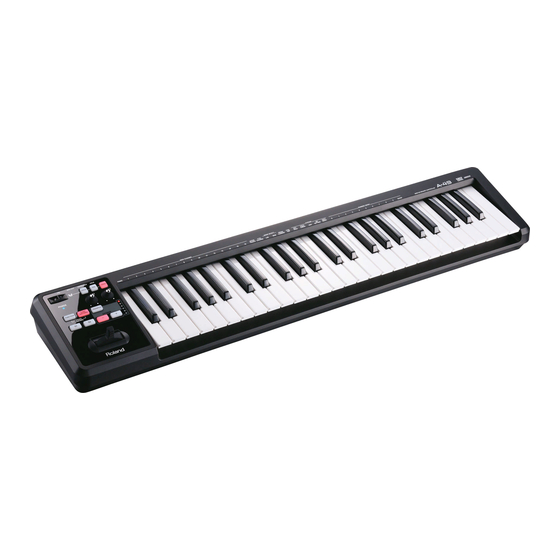
Page 4: Location Of Controls (Top)
Sep. 2012 A-49-BK, A-49-WH Location of Controls (Top) fig.panel.eps Location of Controls Parts List (Top) Part Code Part Name Description Q’ty 5100029489 ESCUTCHEON D-BEAM CONTROLLER 03126134 LED(INFRARED) TLN233(F) 02230578 LED SPACER LDS-50R 01900612 DIODE TPS611(F) 12169368 LED SPACER LDS-40B 5100018908... -
Page 5: Location Of Controls (Rear)
Sep. 2012 A-49-BK, A-49-WH Location of Controls (Rear) fig.rear.eps Location of Controls Parts List (Rear) Part Code Part Name Description Q’ty 00569278 6.5MM JACK LGR4609-7100F 02892878 DIN(MIDI) JACK 2DJ-00600003 5100010665 USB CONNECTOR B TYPE FEMALE 2549A-04G2T(610-02001-04-00) -
Page 6: Exploded View
Sep. 2012 A-49-BK, A-49-WH Exploded View fig.bunkai.eps... -
Page 7: Exploded View Parts List
Sep. 2012 A-49-BK, A-49-WH Exploded View Parts List Part Code Part Name Description Q’ty 03787690 R-KNOB W/INDICATOR BLACK 710-04037-07-01/08-01 5100023836 PANEL SHEET for BK 5100029764 PANEL SHEET for WH 5100023834 TOP CASE for BK 5100029355 TOP CASE for WH 5100029489... -
Page 8: Plane View
Sep. 2012 A-49-BK, A-49-WH Plane View fig.bunkai-H1.eps View 1 View 2 View 3... -
Page 9: Plane View Parts List
Sep. 2012 A-49-BK, A-49-WH Plane View Parts List View 1 Part Code Part Name Description Q’ty 40011323 SCREW 3X10 BINDING TAPTITE P BZC View 2, 3 Part Code Part Name Description Q’ty 40011312 SCREW 3X8 BINDING TAPTITE P FE BZC Keyboard Parts List fig.key-MSK2.eps... -
Page 10: Parts List
Sep. 2012 A-49-BK, A-49-WH Parts List fig.-part1-e.eps Due to one or more of the following reasons, Safety Precautions: parts with parts code ******** cannot be supplied as service parts. The parts marked have safety-related characteristics. Use only listed parts for replacement. -
Page 11: Verifying The Version
Sep. 2012 A-49-BK, A-49-WH Verifying the Version Performing a Factory Reset Press FUNCTION. Items Required At the keyboard, press the key labeled FACT RESET. • Computer At the keyboard, press the key labeled ENTER. • USB cable The factory reset is executed, and parameters that have been set in the Function mode are reset to their factory-default values. -
Page 12: Test Mode
Sep. 2012 A-49-BK, A-49-WH Test Mode Items Required Pedal and Knob Test • Computer Operate the expression pedal connected to the EXPRESSION jack from MIN to MAX. • Expression pedals (EV-5, etc.) x 2 • MIDI sound module Operate the expression pedal connected to the HOLD jack from MIN to •... -
Page 13: Circuit Board (Main Board)
Sep. 2012 A-49-BK, A-49-WH Circuit Board (Main Board) fig.b-main.eps... -
Page 14: Circuit Diagram (Main Board)
Sep. 2012 A-49-BK, A-49-WH Circuit Diagram (Main Board) fig.d-main.eps@L D+3.3V D+3.3V KDS122 DGND 100k AD_HOLD HOLD D+3.3V AK2923H-E2 1000pF LGR4609-7100F DGND AD_C2 DGND AD_C1 D+3.3V AD_HOLD AD_EXPR AD_MOD D+3.3V D+3.3V KDS122 AD_BEND 0.1uF DGND ASEL2 ASEL1 100k AD_EXPR ASEL0 EXPR. - Page 15 Sep. 2012 A-49-BK, A-49-WH fig.d-main.eps@R D+3.3V TP52 10uF DGND 0.1uF 0.1uF 0.1uF 0.1uF 0.1uF 0.1uF DGND DGND 2549A-04G2T D+3.3V VBUS+5V DSX321G 8.000MHZ VDDA OSC_OUT VREF+ VREF- VSSA OSC_IN 10pF 10pF DGND AD_DB DGND PA0-WKUP/USART2_CTS/ADC_IN0/TIM2_CH1_ETR ADIN0 SWD2 PA1/USART2_RTS/ADC_IN1/TIM2_CH2 PC15-OSC32_OUT MIDI-TX EZJZ1V800AA...
-
Page 16: Circuit Board (Panel Board)
Sep. 2012 A-49-BK, A-49-WH Circuit Board (Panel Board) fig.b-panel.eps... - Page 17 Sep. 2012 A-49-BK, A-49-WH...
-
Page 18: Circuit Diagram (Panel Board)
Sep. 2012 A-49-BK, A-49-WH Circuit Diagram (Panel Board) fig.d-panel.eps@L 100k PD+5V 100uH (1.0Amax) CDRH104RNP-101NC-R PQ1CZ41H2ZPH 220uF PDGND VOUT ON/OFF OADJ RB160L-40 TE25(PB FREE) Vref=1.26V 0.1uF PDGND f=300kHz 2.2k F (1%) TP96 A-4.5V (OPAMP-) PD+3.3V XDB_BOOT 0.1uF PD+3.3V PD+3.3V PDGND PD+3.3V... - Page 19 Sep. 2012 A-49-BK, A-49-WH fig.d-panel.eps@R PD+5V 0.1uF TP60 TP62 DBGND TP64 TP65 TP66 SCAN [~12] To MAIN BOARD TP67 TP68 (H-Active) TP69 TP70 LCLK TP71 TP72 PD+3.3V TP73 DB_PLS TP74 AD_C1 TP75 PD+3.3V (L=20mm) AD_C2 TP76 50kB TP77 MOD_V TP78...