Table of Contents
Advertisement
PROFESSIONAL MEDICAL PRODUCTS
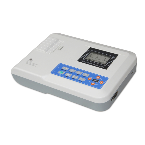
100G CONTEC ECG - 1 channel with monitor
User Manual
ATTENTION: The operators must carefully read and
completely understand the present manual before
using the product.
33220
CONTEC MEDICAL SYSTEMS CO., LTD
No. 112 Qinhuang West Street, Economic & Technical Development Zone,
Qinhuangdao, Hebei Province, PEOPLE'S REPUBLIC OF CHINA
Shanghai International Holding Corp. GmbH (Europe)
Eiffestrasse 80, 20537, Hamburg, Germany
Gima S.p.A.
Via Marconi, 1 – 20060 Gessate (MI) Italy
gima@gimaitaly.com
–
export@gimaitaly.com
www.gimaitaly.com
Advertisement
Table of Contents

Related Manuals for Contec ECG 100G


Summary of Contents for Contec ECG 100G
-
Page 1: User Manual
Via Marconi, 1 – 20060 Gessate (MI) Italy gima@gimaitaly.com – export@gimaitaly.com www.gimaitaly.com PROFESSIONAL MEDICAL PRODUCTS 100G CONTEC ECG - 1 channel with monitor User Manual ATTENTION: The operators must carefully read and completely understand the present manual before using the product. 33220 CONTEC MEDICAL SYSTEMS CO., LTD... -
Page 2: Table Of Contents
User Manual CONTENTS Chapter 1 Main Technical Specification ..................1 Chapter 2 Security Notice ......................2 Chapter 3 Maintenance Regulation ................... 3 Chapter 4 Apparatus Characteristic ................... 4 Chapter 5 ECG100G Panel Sketch Map ................... 6 Chapter 6 Operation Regulation ....................9 Chapter 7 Preparation before Operation ................. -
Page 3: Chapter 1 Main Technical Specification
User Manual Chapter 1 Main Technical Specification 1.1 Normal work environment Operation a) Environment temperature: +5℃~+35℃ b) Relative humidity: ≤80% c) Power supply: AC:100~240V,50/60 Hz DC: 7.4V, 2000 mAh rechargeable lithium battery d) Atmospheric pressure: 86kPa~106kPa Store and Transportation a) Environment temperature: -40℃~55℃ b) Relative humidity: ≤95% c) Atmospheric pressure: 50kPa~106kPa 1.2 Input way: Floating and defibrillation protection... -
Page 4: Chapter 2 Security Notice
User Manual Chapter 2 Security Notice 2.1 Make sure the instrument grounding properly during installation. 2.2 If the ground cable is not integrated, please run the device with battery. 2.3 Please pull out power supply plug before change the fuse. 2.4 This device must be operated and preserved by professional doctor. -
Page 5: Chapter 3 Maintenance Regulation
User Manual Chapter 3 Maintenance Regulation 3.1 Under the condition of normal use according to the user manual and operation notice, if this instrument has any problem, please contact with our customer service department. Our company has the sales record and customer archives for each instrument. The customer has one year's warranty service from the beginning of shipping date according to the below time and condition. -
Page 6: Chapter 4 Apparatus Characteristic
User Manual Chapter 4 Apparatus Characteristic 4.1 Recording system: Thermal-array (8 dots/mm), it needs not be adjusted. Frequency Response: 150Hz (IEC). 4.2 The device can record exact single ECG waveform and remark. The remark includes: lead sign, sensitivity, paper speed, filter state. 4.3 Under automatic mode, just press the button once, it starts record procedure, which can enhance your work efficiency. - Page 7 User Manual Equipotential point Places need to be noticed, please refer to user manual Device type is CF applied part, which has defibrillation protection function PATIENT Lead connector WEEE (2002/96/EC) This item is compliant with Medical Device Directive 93/42/EEC of June 14, 1993, a directive of the European Economic Community.
-
Page 8: Chapter 5 Ecg100G Panel Sketch Map
User Manual Chapter 5 ECG100G Panel Sketch Map A. The sketch map and components name Front view Side view... - Page 9 User Manual Rear view Power Switch Power Plug Earth Terminal Bottom view B. Button definition Function button: ON/OFF & Time Display Function button: plus adjust Function button: paper speed adjust Function button: filter function select Function button: pause/on Function button: switch work mode Function button: marker Function button: print...
- Page 10 User Manual Function button: system menu Function button: upwards Function button: downwards Function button: leftwards Function button: rightwards C. Indicator Definition The indicator turns green when there is AC power supply, and when the indicator turns green and red same time it is being recharged. Indicator for instrument when power on.
-
Page 11: Chapter 6 Operation Regulation
User Manual Chapter 6 Operation Regulation 6.1 You are required to read the operation regulation so as to ensure taking proper operation of the instrument. 6.2 Installation and maintenance of the instrument shall be carried out as the following: 6.2.1 There shouldn't have high voltage cable, X radial engine, ultrasound instruments and electrotherapeutics engine around the ECG. -
Page 12: Chapter 7 Preparation Before Operation
User Manual Chapter 7 Preparation before Operation 7.1 Check that the instrument properly grounded and that cable connections safe or not. 7.2 Check the electrode which connected with patient safe or not 7.3 When power supply is direct current (UPS), please check the voltage of battery before use. 7.4 The gel should be separated from each other and the chest electrodes shouldn't be contacted with the others, as this operation can avoid short circuit. -
Page 13: Chapter 8 Attention During Operation
User Manual Chapter 8 Attention During Operation 8.1 Keep close observation of state of the patient and instrument. 8.2 Make sure that the patient and device only be connected by leads. 8.3 The device and patient can’t be moved during working. 8.4 Turn off device after operation. -
Page 14: Chapter 9 Recording Paper Loading
User Manual Chapter 9 Recording Paper Loading 9.1 If the recording paper is used up during the recording process, the paper record will over, and a notice will be displayed on the LCD screen. 9.2 There is a line at the verge of paper at the last two meters of the recording paper, this line means the paper is not enough, please change the paper immediately. -
Page 15: Chapter 10 Electrode Installation
User Manual Chapter 10 Electrode Installation You'd better install the chest electrode firstly, then Limb electrode. 10.1 Chest electrode, as shown in figure 10-1: Figure 10-1: chest electrode locations The position of installing chest electrodes are as following: V1: Fourth inter-costal space at right border of sternum. V2: Fourth inter-costal space at left border of sternum.. - Page 16 User Manual unit.
- Page 17 User Manual 10.3 Check-List for Electrode connection and ECG cable Electrode Location Electrode Code Socket Number Right Alarm RA/R Left Alarm LA/L Left Leg LL/F Right Leg RL/N Chest 1 Vl/Cl Chest 2 V2/C2 Chest 3 V3/C3 Chest 4 V4/C4 Chest 5 V5/C5 Chest 6...
-
Page 18: Chapter 11 Grounding And Power Connection
User Manual Chapter 11 Grounding and Power Connection Make sure the status of the instrument is power off, and then make the instrument be properly grounded through a 3-prong outlet. When the outlet, a grounding cable may be utilized to connect the grounding terminal of the instrument. -
Page 19: Chapter 12 Battery Operation Regulation
User Manual Chapter 12 Battery Operation Regulation 12.1 This device includes built-in chargeable lithium battery, which needn’t maintenance. This battery is with perfect automatic charge and discharge monitoring system. When you connect power supply adapter with alternating current, the charge will be start automatically. When this device be open, an icon be displayed on top right corner of LCD screen. -
Page 20: Chapter 13 Keypad And Controls
User Manual Chapter 13 Keypad and Controls 13.1 Press power supply key for several seconds, the device will enter auto-check mode, at this time, the display will be boot-strap menu. 13.2 After auto-check mode, the display as following: (1) The operation of lead indicate column Press button to choose relevant lead, the device will switch to appointed lead check state, it switch among according following order: I II III aVR aVL aVF Vl V2 V3... - Page 21 User Manual placed well. Stop printing and print date again after collecting the wave. When the leads state is "DROP", leads shown on the screen have been off .Please reconnect them. (4) Print operation Press under this state, you can start print system setup and ECG wave, press again the device will be turned off.
- Page 22 User Manual Press to enter above interface, you can choose relevant item by press , then you can press to adjust the content, after setup, press to be back. (2)Introduction of every item Backlight: 0-99seconds, back light start time, when choosing 0s, the back light will be turned off, when choosing 99s, the backlight will be turned on for 99s.
-
Page 23: Chapter 14 Troubleshooting
User Manual Chapter 14 Troubleshooting 14.1 Automatic Switch off ① Please check whether the power of battery is used up. Turn off is for protecting circuit. ② Please check whether the alternating current voltage is too high, Turn off is for protecting circuit. - Page 24 User Manual ① Is the installation of the electrode instability? ② Is the connection between leads and electrodes credibility? ③ Check the cleaning of electrode and patient skin. Is the electrode and skin covered with enough Gel? ④ Does it cause by the patients' moving or breathing? ⑤...
-
Page 25: Chapter 15 Maintenance Transportation And Preservation
User Manual Chapter 15 Maintenance Transportation And Preservation 15.1 Customer is not permitted to open the instrument, in archive of any electronic shock. Any maintenance or update should execute by the trained and authorized professionals from our company .The maintenance should be done with the original accessories from our company. 15.2 Please pull out the power supply plug when power off. -
Page 26: Appendix
User Manual Appendix Guidance and manufacture’s declaration – electromagnetic emissions- for all EQUIPMENT and SYSTEMS Guidance and manufacture’s declaration – electromagnetic emission The ECG100G ECG is intended for use in the electromagnetic environment specified below. The customer of the user of the ECG100G ECG should assure that it is used in such and environment. - Page 27 User Manual Guidance and manufacture’s declaration – electromagnetic immunity – for all EQUIPMENT and SYSTEMS Guidance and manufacture’s declaration – electromagnetic immunity The ECG100G ECG is intended for use in the electromagnetic environment specified below. The customer or the user of ECG100G ECG should assure that it is used in such an environment.
- Page 28 User Manual Guidance and manufacture’s declaration – electromagnetic immunity – for EQUIPMENT and SYSTEMS that are not LIFE-SUPPORTING Guidance and manufacture’s declaration – electromagnetic immunity The ECG100G ECG is intended for use in the electromagnetic environment specified below. The customer or the user of ECG100G ECG should assure that it is used in such an environment.
- Page 29 User Manual Recommended separation distances between portable and mobile RF communications equipment and the EQUIPMENT or SYSTEM – for EQUIPMENT or SYSTEM that are not LIFE-SUPPORTING Recommended separation distances between portable and mobile RF communications equipment and the ECG100G ECG The ECG100G ECG is intended for use in an electromagnetic environment in which radiated RF disturbances are controlled.
- Page 30 0123 CONTEC MEDICAL SYSTEMS CO., LTD No. 112 Qinhuang West Street, Economic & Technical Development Zone, Qinhuangdao, Hebei Province, PEOPLE'S REPUBLIC OF CHINA Shanghai International Holding Corp.
- Page 31 User Manual Explanations of symbols on unit Symbol for "applied parts" (the electrodes are type CF applied parts). Symbol for "environment protection" - waste electrical products should not be disposed of with household waste. Please recycle where facilities exist. Check with your local Authority or retailer for recycling advice.