
Related Manuals for Bose T5


Summary of Contents for Bose T5
- Page 1 T5 Tactical Headset ©2016 Bose Corporation Service Manual Reference Number 350006-SM Rev. 00...
-
Page 2: Table Of Contents
IMPORTANT NOTE: These products are RoHS compliant. Use ONLY lead free solder when making repairs. ® CAUTION: The Bose T5 Tactical Headset contains no user serviceable parts. To prevent warranty infractions, refer servicing to warranty service stations or factory service. PROPRIETARY INFORMATION THIS DOCUMENT CONTAINS PROPRIETARY INFORMATION OF... -
Page 3: Electrostatic Discharge Sensitive (Esds) Device Handling
ELECTROSTATIC DISCHARGE SENSITIVE (ESDS) DEVICE HANDLING This unit contains ESDS devices. We recommend the following precautions when repairing, replacing or transporting ESDS devices: • Perform work at an electrically grounded work station. • Wear wrist straps that connect to the station or heel straps that connect to conductive floor mats. -
Page 4: Specifications
SPECIFICATIONS ® Bose T5 TECHNICAL INFORMATION OVERVIEW Mono and stereo available Single Comm and Dual Comm options Weight (on head) 455g Control Module Weight 300g Dual Comm radio or intercom cables 120g (max/each) Nominal Headband Clamping Force 2.1 +/- 0.1 lbs. -
Page 5: Product Description
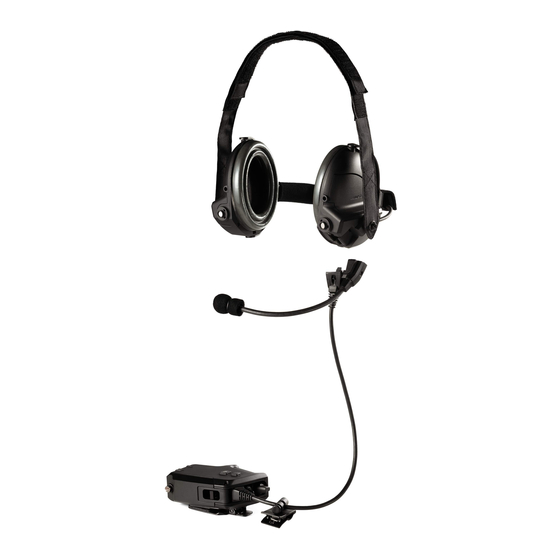
The T5 Tactical Headset is designed to be used by infantry and other military personnel who are primarily operating in and around tactical wheeled vehicles. These users engage in mission- critical communications and require effective noise reduction. -
Page 6: Single Comm Module Controls
PRODUCT DESCRIPTION Single Comm Module Controls Dual Comm Module Controls... - Page 7 PRODUCT DESCRIPTION The T5 headset is capable of working in noise environments with sound pressure levels up to 115dB(C) SPL which means it is most useful in small and large wheeled vehicles as well as many fixed and rotary wing aircraft.
- Page 8 PRODUCT DESCRIPTION The control module switches and buttons are designed to be easily operated while wearing typical work gloves with a material thickness of up to 3mm. They are also designed to provide tactile feedback during operation and configured such that the mode of the switch can be recognized visually or by feel.
- Page 9 PRODUCT DESCRIPTION Operation Modes (Power Compatibility) (continued) Intercom Power (13.6 – 32.0 VDC) • Battery powered ANR - ANR Switch does not operate • Selectable Gain switchable Talk Through • Boom Microphone Output is specific to device it is attached to and is configured inside the input cable.
- Page 10 PRODUCT DESCRIPTION Operation Modes (Audio Management) Dual Comm Versions (continued): Port 2 is intended to be a secondary communications port. The presentation of this source’s audio to the headset depends upon the presence of a cable plugged into Port 1. If Port 1 has a cable plugged in, the audio from the Port 2 device will only be presented to the left earcup.
-
Page 11: Manufactured Versions
CASE, HEADSET, T5 361424-0010 HEADPHONE ASSY,T5,W/NAPEBAND,SPARE 370075-0010 MOD ASSY, W/O BOOM MIC, T5, SINGLE, 370250-1100 MONAURAL MOD ASSY, W/O BOOM MIC, T5, SINGLE, 370250-1200 BINAURAL MOD ASSY, W/0 BOOM MIC, T5, DUAL, COMM 370250-2000 HEADPHONE ASSY W/NAPEBAND, T5 370075-0010 ... -
Page 12: System Configurations
System Configurations... - Page 13 System Configurations (continued)
-
Page 14: Cables And Replacement Parts
Cables and Replacement Parts... -
Page 15: Disassembly Procedures
DISASSEMBLY PROCEDURES IMPORTANT NOTE: These products are RoHS compliant. Use ONLY lead free solder when making repairs. 1. Boom Microphone Replacement 1.1 Loosen the captive screw that retains the boom microphone base to the left earcup. 1.2 Gently pull the base of the boom micro- phone away from the earcup. - Page 16 DISASSEMBLY PROCEDURES 2.4 Align and press the replacement ear cushion onto the earcup assembly until it snaps into place. Ensure it is fully seated. 3. Nape Band Replacement Yoke pin 3.1 Remove nape band cover 3.2 Press upward on nape band yoke until the yoke pin clears the earcup.
- Page 17 DISASSEMBLY PROCEDURES boom microphone assembly straight down and away from the earcup. It should unplug from the left earcup connector as a unit. 5. Control Module Replacement Note: The control module is not repairable. It is a sealed unit. The control module cables are not replaceable separately from the control module.
- Page 18 DISASSEMBLY PROCEDURES control module cable straight down. It should unplug from the bottom of the left earcup. 6. Battery Cover Replacement 6.1 On the control module, loosen the captive screw that holds the battery door closed over the batteries. Do not completely remove the screw.
- Page 19 DISASSEMBLY PROCEDURES outward on each earcup. When worn, the straps should interlock without twisting. 8. Attachment Clip Replacement / Relocation 8.1 Remove the screw securing the attach- ment clip to the control module. 8.2 Align the square alignment holes on the replacement clip to the alignment feature on the control module and secure with the screw removed in step 8.1.
-
Page 20: Test Procedures
Note: The following procedures contain two Test Setup separate test procedures. • Install two AA batteries into the control The first test is for internal Bose ® repair module for talk through capability. centers that have the required Bose final •... - Page 21 TEST PROCEDURES 1. Active Noise Reduction (ANR) Operation, 2.2 Slowly compress the cups against the Quiet Environment head with your hands. Move the earcups with your hands to simulate rapid head and Setup Conditions: jaw movement. Listen for overload or instability conditions.
- Page 22 TEST PROCEDURES PASS/FAIL Criteria. Words should be heard 5. Talk-Through Operation, ANR ON clearly and be recognizable. This test is to verify Talk- through balance, 3.6 Talk-through Compressor Operation. and intelligibility. Listen to the audio signal. Move the gain switch to the +15dB position. Wait for the Set-Up Conditions: sound of words to stablilize before listening •...
- Page 23 TEST PROCEDURES PASS/FAIL Criteria. The level of sound 1.2 Play an audio signal to the headset. heard through the talk-through must not Verify that you can hear the audio being fed in-crease dramatically after the sound of to the headset from the radio or intercomm. the words stabilizes.
- Page 24 TEST PROCEDURES 2. Active Noise Reduction (ANR) Opera- 3.2 Slowly compress the cups against the tion, Quiet Environment head with your hands. Move the earcups with your hands to simulate rapid head and Setup Conditions: jaw movement. Listen for overload or insta- bility conditions.
- Page 25 TEST PROCEDURES 4.6 Talk-through Compressor Operation. 6. Talk-Through Operation, ANR ON Listen to the audio source. Move the gain switch to the +15dB position. Wait for the This test is to verify Talk- through balance, sound of words to stablilize before listening and intelligibility.
- Page 26 TEST PROCEDURES PASS/FAIL Criteria. The level of sound heard through the talk-through must not in-crease dramatically after the sound of the words stabilizes. If verification is needed compare ambient sound at increased gain level to sound heard through the talk- through system.
-
Page 27: Troubleshooting
The headset is field repairable at a higher level, i.e. control module, earcups, cables, etc. The list of user replaceable parts is located on page 11 of this manual. Problems associated with the headset (driver faults, earcup PCB faults, etc.) require the product to be returned to Bose Corporation for repair. - Page 28 Troubleshooting Symptom Verification/Solution No Output from Check for damage or contamination, i.e. rust, chewing tobacco, Microphone debris. If mic is damaged or contaminated, replace it. Check microphone connection to the headset. Ensure wiring harness Low microphone is not damaged and that the connector pins are not bent and output, intermittent connector is properly seated.
- Page 29 Troubleshooting Symptom Verification/Solution Mic Live Switch not By design, the Mic live switch has no effect on any Port 2 device working on Port 2 under any configuration. (Dual Comm versions) Live Mic Button Not Button is located on the back of the control module. This button is Working only enabled while operating from vehicle power.
-
Page 30: Service Manual Revision History
Service Manual Revision History Date Revision Description of Change Change Driven Pages Level Affected 3/2016 Document released at revision 00. Service manual release ... - Page 31 Specifications and Features Subject to Change Without Notice Bose Corporation The Mountain Framingham Massachusetts USA 01701 P/N: 350006-SM REV. 00; 3/2016 (M) http://serviceops.bose.com...