Makita HM1202 Technical Information
Hide thumbs
Also See for HM1202:
- Instruction manual (45 pages) ,
- Instruction manual (8 pages) ,
- Instruction manual (25 pages)
Advertisement
Quick Links
Download this manual
See also:
Instruction Manual
T
ECHNICAL INFORMATION
Models No.
Description
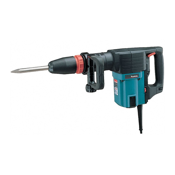
CONCEPTION AND MAIN APPLICATIONS
These demolition hammers are newly developped
as a 10 Kg hammer. (middel class between
HM1201 and HM1303 series models.)
Considerable strong demolishing power in this class,
However, softened reaction.
Model HM1202C : equipped with electronic control system
Model HM1202 : without the above features.
Specifications
Voltage (V)
HM1202 HM1202C
100
110
120
13.0
220
230
240
Bit-type
Blows per minute
Net Weight
Size of shank
Cord Length
Standard equipment
Bit Grease
Bull-Point 280
Optional accessories
Bull Point 280
Bull Point 400
Cold Chisel 25x280
Cold Chisel 25x400
The standard equipment for the tools shown may differ form country to country.
HM1202, HM1202C
Demolition Hammers
and variable speed control dial.
Current (A)
Cycle (Hz) Input
15.0
15.0
14.0
15.0
13.0
6.8
7.3
6.5
7.0
6.7
6.3
HM1202C
HM1202
Scaling Chisel 50x400
Clay Spade 105x400
Hammer Grease
Continuous Rating (W)
HM1202 HM1202C HM1202 HM1202C
700
700
700
1,450
50/60
750
750
750
SDS-Max
950-1900 (bpm)
1900 (bpm)
9.3kg (20.5 lbs)
18mm (11/16")
5m (16.4 ft)
112mm(4-3/8")
Max. Output(W)
Output
1500
500
1500
500
1500
500
1600
550
1600
550
550
1600
Product
P 1 / 14
1600
1600
1600
1800
1800
1800
Advertisement

Related Manuals for Makita HM1202


Summary of Contents for Makita HM1202
- Page 1 HM1201 and HM1303 series models.) Considerable strong demolishing power in this class, However, softened reaction. Model HM1202C : equipped with electronic control system and variable speed control dial. Model HM1202 : without the above features. Specifications Continuous Rating (W) Max. Output(W) Current (A)
- Page 2 P 2 / 14 Repairing Screwdriver <1> Dismounting of armature (1) Take off the rear cover from the motor housing by loosening 2 pcs.of tapping screw M4x18. And then take off the carbon brushes after taking off the brush holder cap. Brush Holder Cap Tapping screw M4x18 (2) Take off the handle and controller cover...
- Page 3 P 3 / 14 (5) Dismounting of ball bearing 6304LLU from crank shaft. Insert the repairing jig 1R234, 1R240 and 1R241 into the arbor on the crank shaft as per the following illustration. And then, press with arbor press. So, Ball bearing 6304LLU can be dismounted. Arbor press 1R032 - 1R037 1R234...
- Page 4 P 4 / 14 (2) Take off ring spring 25 and retaining ring WR-45 with repairing tool No.1R212. Then, the spare parts on the chuck section can 1R212 be dismounted in the order from the bit side. Retaining ring WR-45 Cup Washer 45 Compression spring 55 <3>...
- Page 5 (3) Hold cylinder liner 44 with hand and P 5 / 14 strike crank housing with plastic or wooden hammer. Then the cylinder liner 44 can be removed from the machine. Cylinder liner 44 Crank housing (Mounting) Mount slide sleeve 49, ring 49 and compression spring 50 on cylinder liner 44.
- Page 6 P 6 / 14 (Mounting) (1)Make sure that urethane ring 43 and O ring 38 are mounted on tool holder in dvance. If not, mount them on the tool holder. Insert impact bolt into tool holder, and mount the tool holder in barrel. Barrel Tool holder Impact bolt...
- Page 7 < 5> Mounting of fluoride ring P 7 / 14 (Mounting) (1) Fluoride ring 28, just after mounted, can not be fit precisely along the groove on the impact bolt. The edge come out from the groove. (2) Insert the impact bolt on which the fluoride ring 28 is attached, into repairing jig No.1R-214.
- Page 8 P 8 / 14 < 6> Mounting of barrel Take off only handle, not remove controller cover. (1) Set the of the guide ring on the of flat washer 49. Mount the above guide ring and flat washer 49 on the 3 prongs of slide sleeve 49.
- Page 9 (5) Wipe out the grease in the crank housing with cloth. And then, apply fresh MAKITA grease No.00 by 30g. < Remarks > The fresh grease to be applied has to be limited to 30 g.
- Page 10 P 10 / 14 The parts to be greased The parts to be greased are marked with (1) The parts to be greased with MAKTA grease No.00. Impact bolt : Inner side of O ring, Out side of fluoride ring 28, Whole part of impact bolt.
- Page 11 P 11 / 14 Cylinder liner 44: Surface marked with Ring 49 Slide sleeve 49 Cylinder liner 44 Barrel : Inner part marked with Crank shaft : Whole of gear part marked with (2) The parts to be greased with MAKTA grease No.2. Tool holder Pin 8 Hole for steel ball 5.6 (Barrel)
- Page 12 F2. White r3. White Tube r2. Black Controller Switch r1. Red Power supply cord F1. Black Pick up coil HM1202 without controller Black Black F2. White F1. Black Noise suppressor C1. White Switch In some countries, C2. White Noise suppressor is not Power supply cord used.
- Page 13 Circuit diagram P 13 / 14 HM1202C with controller Lead wire "r1(Red)" has to be guided through rib A as per the illustration. Rib A Lead wire "r1"(red) Lead wire from field (F1.Black) and (F2. White) has to be fixed by lead holder as per the illustration.
- Page 14 P 14 / 14 HM1202 without controller Lead wire F1. Black and F2. White Power supply cord has to be from field have to be set in the groove. set in the groove. F2. White F1.Black Power supply cord Condenser...