NEC WMK-3257 Installation And Assembly Manual
Flat screen wall mount for models: aspv32, aspv40, e321, e421, e461, lcd3210, lcd3215, lcd4020, lcd4215, lcd4615, lcd4620, lcd5220, lcd5710, m40, m46, p401, p461, p521, p551, s401, s461, s521, sc40, sc46, v321, v421, v461, x431bt, x461hb, x461un, e324, ma
Advertisement
Quick Links
NEC DISPLAY SOLUTIONS OF AMERICA, INC.
Installation and Assembly - Flat Screen Wall
Mount for NEC models:
ASPV32, ASPV40, E321, E421, E461,
LCD3210, LCD3215, LCD4020, LCD4215,
LCD4615, LCD4620, LCD5220, LCD5710,
M40, M46, P401, P461, P521, P551, S401,
S461, S521, SC40, SC46, V321, V421, V461,
X431BT, X461HB, X461UN, E324
This product is intended for use with UL
Listed products and must be installed by a
qualifi ed professional installer.
Maximum UL Load Capacity: 150 Ib (68 Kg)
ISSUED: 03-26-10 SHEET #: 125-9106-6 12-11-14
Model: WMK-3257
Advertisement

Related Manuals for NEC WMK-3257


Summary of Contents for NEC WMK-3257
- Page 1 Installation and Assembly - Flat Screen Wall Mount for NEC models: ASPV32, ASPV40, E321, E421, E461, NEC DISPLAY SOLUTIONS OF AMERICA, INC. Model: WMK-3257 LCD3210, LCD3215, LCD4020, LCD4215, LCD4615, LCD4620, LCD5220, LCD5710, M40, M46, P401, P461, P521, P551, S401, S461, S521, SC40, SC46, V321, V421, V461,...
-
Page 2: Table Of Contents
Note: Read entire instruction sheet before you start installation and assembly. WARNING • Do not begin to install this product until you have read and understood the instructions and warnings contained in this Installation Sheet. If you have any questions regarding any of the instructions or warnings, please call customer care at 1-800-865-2112. -
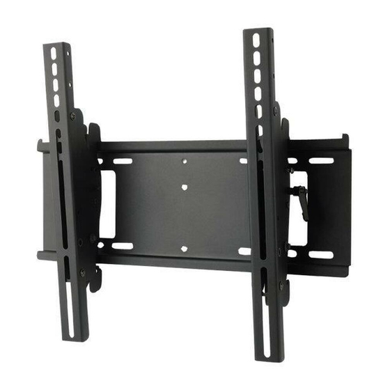
Page 3: Parts List
Tools Needed for Assembly • stud fi nder ("edge to edge" stud fi nder is recommended) • phillips screwdriver • drill • 1/4" bit for concrete and cinder block wall • 5/32" bit for wood stud wall • level Before you begin, make sure all parts shown are included with your product. Parts may appear slightly different than illustrated. -
Page 4: Installation To Double Wood Stud Wall
Installation to Double Wood Stud Wall WARNING • Installer must verify that the supporting surface will safely support the combined load of the equipment and all attached hardware and components. • Tighten wood screws so that wall plate is fi rmly attached, but do not overtighten. Overtightening can damage the screws, greatly reducing their holding power. -
Page 5: Installation To Solid Concrete Or Cinder Block
Installation to Solid Concrete or Cinder Block WARNING • When installing Peerless wall mounts on a concrete wall, the wall must be at least 8" thick with a minimum compres- sive strength of 2000 psi. • When installing Peerless wall mounts on a cinder block wall, the cinder blocks must meet ASTM C-90 specifi cations and have a minimum nominal width of 8". -
Page 6: Installing Tilt Brackets
Orientation Use Chart to Determine and Screws Secure extension brackets (L) to left LANDSCAPE PORTRAIT tilt bracket (B) with four M5 x 6 mm Recommended Hole Pattern Recommended Hole Pattern socket pin serrated washer head A 100 mm x 100 mm D 400 mm X 400 mm 100 mm x 100 mm 400 mm X 400 mm... -
Page 7: Installing Flat Panel Screen To Wall Plate
Mounting and Removing Flat Panel Screen WARNING • Always use an assistant or mechanical lifting equipment to safely lift and position the fl at panel screen. • Do not tighten screws with excessive force. Overtightening can cause damage to mount. Tighten screws to 40 in.