EMC VNX Series Hardware Information Manual
Hide thumbs
Also See for VNX Series:
- Hardware information manual (170 pages) ,
- Installation manual (92 pages) ,
- Parts location manual (56 pages)
Advertisement
Table of Contents
- 1 Table of Contents
- 2 Product Software and Hardware Release Revisions
- 3 Revision History
- 4 Where to Get Help
- 5 How this Document Is Organized
- 6 Related Documentation
- 7 Overview
- 8 VNX5300 Block and File Product Description
- 9 System Component Description
- 10 I/O Modules
- 11 Disk-Array Enclosure
- 12 Cabling
- 13 VNX5300 DAE Cabling
- Download this manual
See also:
Hardware Information Manual
®
™
EMC
VNX
Family
™
VNX5300
Hardware Information Guide
P/N 300-013-308
Rev 01
June 25, 2012
This guide describes one of five models available in the VNX Series, the EMC
VNX5300™. This document provides an overview of the architecture, components, and
features of the VNX5300 platform. The specific aspects of the VNX5300 platform and its
major components include the front and rear connectors and LED indicators on the 3U, 15
(3.5-inch) or 3U, 25 (2.5-inch) disk processor enclosure (DPE), the 1U standby power
supply (SPS), the 1U Control Station, the 2U Data Mover Enclosure (DME), and the 3U, 15
(3.5-inch) or the 2U, 25 (2.5-inch) disk drive disk-array enclosure (DAE).
This guide is available online at https://mydocs.emc.com/VNX/. Go to the About VNX
section, and then select Learn about VNX. Next, follow the steps in the wizard.
Topics include:
Product software and hardware release revisions ...................................................... 2
◆
Revision history ........................................................................................................ 2
◆
Where to get help...................................................................................................... 2
◆
How this document is organized ............................................................................... 3
◆
Related documentation............................................................................................. 3
◆
Overview................................................................................................................... 4
◆
VNX5300 Block and File product description ............................................................. 6
◆
System component description ............................................................................... 11
◆
I/O modules............................................................................................................ 46
◆
Disk-array enclosure................................................................................................ 68
◆
Cabling ................................................................................................................... 85
◆
VNX5300 DAE cabling ............................................................................................. 86
◆
®
Advertisement
Table of Contents

Related Manuals for EMC VNX Series


Summary of Contents for EMC VNX Series
-
Page 1: Table Of Contents
June 25, 2012 ® This guide describes one of five models available in the VNX Series, the EMC VNX5300™. This document provides an overview of the architecture, components, and features of the VNX5300 platform. The specific aspects of the VNX5300 platform and its major components include the front and rear connectors and LED indicators on the 3U, 15 (3.5-inch) or 3U, 25 (2.5-inch) disk processor enclosure (DPE), the 1U standby power... -
Page 2: Product Software And Hardware Release Revisions
Product software and hardware release revisions Product software and hardware release revisions As part of an effort to improve its product lines, EMC periodically releases revisions of its software and hardware. Therefore, some functions described in this document might not be supported by all versions of the software or hardware currently in use. -
Page 3: How This Document Is Organized
The cabling can be either interleaved or stacked depending on your specific requirements. Related documentation EMC provides the ability to create step-by-step planning, installation, and maintenance instructions tailored to your environment. To create VNX customized documentation, go to: https://mydocs.emc.com/VNX/. -
Page 4: Overview
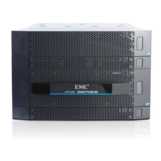
Support for File (CIFS and NFS), Block (FC, iSCSI & FCoE) and Object ◆ Simple conversions when starting with a VNX series Block only platform by simply ◆ adding File services or starting with File only and adding Block services Support for both block and file auto-tiering with Fully Automated Storage Tiering ◆... - Page 5 As a mid-range/entry level storage platform offering Block, File, and Unified services, the VNX5300 platform (Figure 1) is one of the five models that make up the VNX series. For a quick look at the VNX5300 platform hardware features, see Table 1, “VNX5300 hardware feature quick reference,”...
-
Page 6: Vnx5300 Block And File Product Description
(Unified) VNX5300 platform looks like and are for illustrative purposes only. 2. The term Data Mover is used throughout this guide. The term Data Mover is also referred to as a blade. These terms are interchangeable and mean the same thing. EMC VNX5300 Hardware Information Guide... - Page 7 DPE (with two SPs) can have either 15 (3.5-inch) drives or 25 (2.5-inch) drives. Separately, the 15 (3.5-inch) drives weigh 34 lb (15.42 kg) and the 25 (2.5-inch) drives weigh 13.5 lb (6.13 kg), respectively. EMC VNX5300 Hardware Information Guide...
- Page 8 – Four integrated 8-Gb/s FC ports (labeled 2, 3, 4, and 5) supporting 2, 4, and 8 Gb/s having front end auto-negotiation with support for manual override – Two integrated 6-Gb/s SAS x4 ports (labeled 6Gb SAS 0 x4 and 1 x4); supported speeds are 1.5, 3, and 6 Gb/s EMC VNX5300 Hardware Information Guide...
- Page 9 4. The two-port 10-Gb/s and FCoE I/O modules can also use active twinaxial (Twinax) cables. Twinax is a type of cable similar to coax, but with two inner conductors instead of one. These cables will be supplied in lieu of SFP+ transceiver modules when so ordered. EMC VNX5300 Hardware Information Guide...
- Page 10 DAEs for the Block and File (Unified) VNX5300 platform. Any required cables including LAN cables, modem cables, and serial DB-9 cable. ◆ Mounting rails with hardware ◆ Front bezel with VNX5300 badge ◆ EMC VNX5300 Hardware Information Guide...
-
Page 11: System Component Description
Disk drive activity/fault LEDs are integrated into the carrier. The “3U, 15 (3.5-inch) DPE” section on page 12 or the “3U, 25 (2.5-inch) DPE” section on page 14 provides more information. EMC VNX5300 Hardware Information Guide... - Page 12 3U, 15 (3.5-inch) DPE On the front, the Block and File (Unified) VNX5300 platform 3U, 15 (3.5-inch) DPE carrier includes the following: 3.5-inch 6-Gb/s SAS or 6-Gb/s NL-SAS disk drives (hot-swappable) ◆ Status LEDs ◆ EMC VNX5300 Hardware Information Guide...
- Page 13 Powering and powered up with backend bus running at 2 Gb/s Blue Powering and powered up with backend bus running at 6Gb/s — Powered down Disk drive fault (location 4) Amber Fault has occurred — No fault has occurred EMC VNX5300 Hardware Information Guide...
- Page 14 2.5-inch 6-Gb/s SAS or 6-Gb/s NL-SAS Disk drive fault LED (amber) disk drives DPE fault LED (amber) Disk drive status/activity (blue) DPE power status LED (blue) Figure 5 VNX5300 platform 3U, 25 DPE carrier (front view) EMC VNX5300 Hardware Information Guide...
- Page 15 CNS-001740 DVD-ROM drive USB 2.0 connector (not used) Control Station switch and status LEDs (for a closer view, see Figure 7 on page Figure 6 VNX5300 platform Control Station (front view) EMC VNX5300 Hardware Information Guide...
- Page 16 Table 4 Control Station switch Switch Description Power push-button Toggles the 1U Control Station (location 1) power (push in and hold for about 10 seconds) Table 5 on page 17 describes the LEDs located on the front panel. EMC VNX5300 Hardware Information Guide...
- Page 17 — No hard drive activity Onboard (integrated) Green NIC link/no access Ethernet NIC 1 and 2 Blinking NIC link/LAN access (locations 5 and 6, respectively) 1. The system status LED flashes green while booting up. EMC VNX5300 Hardware Information Guide...
- Page 18 Description Power Blue DME is powered up and all the components in the enclosure are operating properly — DME is powered down. Fault Amber A replaceable component failed within the enclosure. — DME operating normally. EMC VNX5300 Hardware Information Guide...
- Page 19 Data Mover is unsafe to remove. remove — Data Mover is safe to remove. Note: The fault LED changes color from amber to blue when the operating system is loading, see step 4 in the description. EMC VNX5300 Hardware Information Guide...
- Page 20 SPS AC power inlet to the AC-DC converter. This converter then converts the AC power to DC power, which is then stored into the built-in DC battery pack. When emergency power is needed by the Block and File (Unified) VNX5300 platform SP, a EMC VNX5300 Hardware Information Guide...
- Page 21 SP B power supply. 5. After a full power outage, an SPS typically requires 45 minutes or a maximum of 75 minutes to charge. To charge the SPS after being off-line usually requires at least 2 hours. EMC VNX5300 Hardware Information Guide...
- Page 22 Figure 11 Example of SPS B and A viewing from left to right (rear view) SPS LEDs Figure 12 shows the LEDs located on each SPS (A and B). SPS power SPS battery SPS no battery SPS fault VNX-000289 Figure 12 SPS LEDs EMC VNX5300 Hardware Information Guide...
- Page 23 R-J12 jack. But an RJ-12 plug will fit into an RJ-45 jack. Use caution when connecting cables. To avoid electric shock, do not attempt to connect TNV circuits to SELV circuits. EMC VNX5300 Hardware Information Guide...
- Page 24 RJ-12 connector (SPS side) on one end and a micro DB-9 connector (SP side) on the other end. Figure 14 shows an example of an SPS A to SP A cable. RJ-12 DB-9 VNX-000283 Figure 14 Example of SP A (micro DB-9) to SPS (RJ-12) cable EMC VNX5300 Hardware Information Guide...
- Page 25 • Four 8-Gb/s Fibre Channel ports (labeled 8Gb fibre 2, 3, 4, and 5) • Two (RJ-45) LAN connectors (labeled with a network management symbol and a wrench symbol) • Two (micro DB-9) RS-232/EIA connectors (labeled with a battery symbol and a wrench symbol) EMC VNX5300 Hardware Information Guide...
- Page 26 Two SP latch handles (bottom left and Four 8-Gb/s Fibre Channel ports (labeled right) 8Gb fibre 2, 3, 4, and 5) Two 6-Gb/s SAS ports (labeled 6Gb SAS 0 x4 and 1 x4) Figure 16 Example of SP components (rear view) EMC VNX5300 Hardware Information Guide...
- Page 27 SP LEDs. The locations in Table 12 are shown in Figure 16 on page Table 12 SP LEDs Color State Description Do not Unsafe to White remove SP remove — Safe to remove SP (location 10) EMC VNX5300 Hardware Information Guide...
- Page 28 Note: Each SAS cable is keyed with an connection to prevent incorrect cabling. Figure 18 shows an example of the port connector (socket) and cable connector (plug) with pull tab. Pin A1 VNX-000094 Figure 18 SP 6-Gb/s SAS port and cable connector EMC VNX5300 Hardware Information Guide...
- Page 29 Link/activity Blue All lanes are running at 6 GB/s Green One or more lanes is not running at full speed or disconnected Alternating Blinking Port is being marked by the host Blue/Green — Not connected EMC VNX5300 Hardware Information Guide...
- Page 30 (for example A1 and A2 for the TX and RX, respectively) or a white and yellow rubber gasket (jacket) for the send or transmit (TX) and receive (RX) ends (Figure 21 on page 31). EMC VNX5300 Hardware Information Guide...
- Page 31 Small form-factor pluggable (SFP+ ) transceiver Blue module faulted, unsupported, or optical cable fault. — No network connection VNX5300 Parts Location Guide 1. Refer to the for part number label location for the SFP+ part number. EMC VNX5300 Hardware Information Guide...
- Page 32 EIA Category 6, up to 1,804 ft (550 m), Category 5E UTP (2 pairs) up to 1,148 ft (350 m) 10GBASE-T EIA Category 7 STP, backwards compatible with Cat 5 and 6, from 2,296.5 to 3,280.8 ft (700 to 1000 m) EMC VNX5300 Hardware Information Guide...
- Page 33 SP Ethernet (RJ-45) port LEDs—a green LED to the left of the connector and a bi-color (green/amber) LED to the right of the connector—that indicate the link/activity and speed of the Ethernet ports, respectively. VNX-000110 Figure 25 Network management and service laptop Ethernet (RJ-45) port LEDs EMC VNX5300 Hardware Information Guide...
- Page 34 SP serial RS-232/EIA 232 (micro DB-9) pin signals used on the connector. Table 19 Serial RS-232/EIA 232 (micro DB-9) connector (socket) pinout DB-9 Pin Signal Description Carrier detect Received data Transmitted data Data terminal ready Ground Data set ready EMC VNX5300 Hardware Information Guide...
- Page 35 RJ-12 modular jack adapter (pins 1, 7, and 8 are used) on the other end. The RJ-12 modular jack adaptor end connects to the RJ-12 modular jack connector on the SPS (Figure 14 on page 24). Pin 1 VNX-000105 Figure 28 Serial RS-232/EIA 232 (micro DB-9) connector (socket) EMC VNX5300 Hardware Information Guide...
- Page 36 Two-port 10-Gb/s optical or active Twinax Fibre Channel over Ethernet (FCoE) ◆ SP I/O Module Slots PART NUMBER PART NUMBER fibre 6Gb SAS 0 X4 VNX-000569 Figure 29 Example of SP with a Fibre Channel (FC) I/O module and an iSCSI I/O module EMC VNX5300 Hardware Information Guide...
- Page 37 1U Control Station. One (DB-9 plug) serial console (RS-232/EIA-232) connector ◆ Two USB 2.0 connectors—not used ◆ POST diagnostic LEDs ◆ Two CAT-5E/6 panel-mount Ethernet cable extensions ◆ EMC VNX5300 Hardware Information Guide...
- Page 38 Ethernet ports (labeled A and CS) and two Peripheral Component Interconnect Express (PCI-E) low profile card dual-port Ethernet ports (labeled B and MGMT) in an expansion slot on the rear of the Control Station. These ports provide an EMC VNX5300 Hardware Information Guide...
- Page 39 Bidirectional pair C, + BI_DC- Bidirectional pair C, - 6. PCI Express is used in consumer, server, and industrial applications, as a motherboard-level interconnect (to link motherboard-mounted peripherals) and as an expansion card interface for add-in boards. EMC VNX5300 Hardware Information Guide...
- Page 40 CS 0, port B to Data Mover Enclosure 0, management module B, port 1 and CS 0, MGMT port to the public LAN. Each cable includes a corresponding label wrap to assist you during system cabling (Figure 33 on page 41). EMC VNX5300 Hardware Information Guide...
- Page 41 Table 24 Control Station (DB-9) plug connector pinout DB-9 Pin Signal Description Carrier detect Received data Transmitted data Data terminal ready Ground Data set ready Request to send Clear to send Ring indicator (not used) EMC VNX5300 Hardware Information Guide...
- Page 42 2U DME rear view with two Data Movers (each Data Mover has one management module, one four-port 8-Gb/s FC I/O module, thee two-port 1-Gb/s plus two-port 1-Gb/s optical I/O modules, and one filler panel module). EMC VNX5300 Hardware Information Guide...
- Page 43 Data Mover management module push RJ-45 Ethernet NIC port (labeled 0) button latch handle RJ-45 Ethernet NIC port (labeled 1) RJ-45 Ethernet NIC port (labeled 2) DME ID numeric display Figure 37 Data Mover management module EMC VNX5300 Hardware Information Guide...
- Page 44 Port 2 (Activity LED) Port 1 (Activity LED) Port 2 (Link LED) Port 1 (Link LED) Port 0 (Link LED) Port 0 (Activity LED) Numeric display (DME ID) CNS-001671 Figure 38 Data Mover management module LEDs EMC VNX5300 Hardware Information Guide...
- Page 45 Data Mover management module Ethernet (DB-9) pin signals used on the connector. Table 27 Data Mover management module (DB-9) socket connector pinout DB-9 Pin Signal Description Carrier detect Transmitted data Received data Data terminal ready EMC VNX5300 Hardware Information Guide...
-
Page 46: I/O Modules
HBA or FC switch. OM2 cabling can usually be distinguished by the orange color of the cable. While, OM3 cabling can be distinguished by the aqua color of the cable. EMC VNX5300 Hardware Information Guide... - Page 47 (TX) and receive (RX) ferrules (connector ends), these cables will show a letter and numeral (for example A1 and A2 for the TX and RX, respectively) or a white and yellow rubber gasket (jacket) for the send or transmit (TX) and receive (RX) ends. EMC VNX5300 Hardware Information Guide...
- Page 48 1 Gb/s. The 1 Gb/s Ethernet Base-T copper ports connect to Cat 6 cabling (see Table 16, “Ethernet cabling guidelines,” page 32 Table 21, “Ethernet cabling guidelines,” page 39) to an Ethernet switch. This I/O module also includes a TCP offload engine (or TOE). EMC VNX5300 Hardware Information Guide...
- Page 49 I/O modules CNS-001751 Push button latch handle RJ-45 NIC link LED Power/fault LED RJ-45 NIC activity LED RJ-45 NIC (copper) port (four) Figure 42 Four-port 1-Gb/s copper iSCSI I/O module EMC VNX5300 Hardware Information Guide...
- Page 50 7. The two-port 10-Gb/s I/O module can also use active twinaxial (Twinax) cables. Twinax is a type of cable similar to coax, but with two inner conductors instead of one. These cables will be supplied in lieu of the SFP+ when so ordered. EMC VNX5300 Hardware Information Guide...
- Page 51 The two-port 10-Gb/s optical I/O module has three types of status LEDs. Figure 45 shows the LEDs and Table 30 on page 52 describes them. Power/fault LED Link LED Activity LED Link LED Activity LED CNS-001672 Figure 45 Two-port 10-Gb/s optical I/O module LEDs EMC VNX5300 Hardware Information Guide...
- Page 52 8. The FCoE I/O module can also use active twinaxial (Twinax) cables. Twinax is a type of cable similar to coax, but with two inner conductors instead of one. These cables will be supplied in lieu of the SFP+ when so ordered. EMC VNX5300 Hardware Information Guide...
- Page 53 Description Power/Fault Green I/O module is powered up. Amber I/O module has faulted. — I/O module is powered down. Link Green Network connection — No network connection Activity Amber Blinking Transmit/receive activity — No activity EMC VNX5300 Hardware Information Guide...
- Page 54 Table 16, “Ethernet cabling guidelines,” page 32 Table 21, “Ethernet cabling guidelines,” page 39). VNXe-000751 Push button latch handle Link LED (right) Power/fault LED Activity LED (left) RJ-45 Base-T port (2) Figure 48 Two-port 10-Gb/s RJ-45 Base-T I/O module EMC VNX5300 Hardware Information Guide...
- Page 55 Description Power/Fault Green I/O module is powered up. Amber I/O module has faulted. — I/O module is powered down. Link Green Network connection — No network connection Activity Amber Blinking Transmit/receive activity — No activity EMC VNX5300 Hardware Information Guide...
- Page 56 While, OM3 cabling can be dis tin gui sed by the aqua color of the cable. CNS-001752 Push button latch handle SFP+ (optical) port (four) Power/fault LED SFP+ link/activity LED Figure 50 Four-port 8-Gb/s FC I/O module EMC VNX5300 Hardware Information Guide...
- Page 57 Figure 51 Four-port 8-Gb/s FC I/O module LEDs Table 33 Four-port 8-Gb/s FC I/O module LEDs Color State Description Power/Fault Green I/O module is powered up. Amber I/O module has faulted. — I/O module is powered down. EMC VNX5300 Hardware Information Guide...
- Page 58 I/O modules will be the SFP transceiver modules used on ports 2 and 3. CNS-001751 Push button latch handle RJ-45 NIC link LED Power/fault LED RJ-45 NIC activity LED RJ-45 NIC (copper) port (four) Figure 52 Four-port 1-Gb/s copper I/O module EMC VNX5300 Hardware Information Guide...
- Page 59 Amber I/O module has faulted. — I/O module is powered down. Link (each Green Network connection port has — No network connection one) Activity Amber Blinking Transmit/receive activity (each port — No activity has one) EMC VNX5300 Hardware Information Guide...
- Page 60 SFP+ activity LED (left) Power/fault LED Two RJ-45 (copper) ports Two SFP+ (optical) ports RJ-45 link LED (right) SFP+ link LED (right) RJ-45 activity LED (left) Figure 54 Two-port 1-Gb/s copper plus two-port 1-Gb/s optical I/O module EMC VNX5300 Hardware Information Guide...
- Page 61 Amber I/O module has faulted. — I/O module is powered down. Link (each Green Network connection port has — No network connection one) Activity Amber Blinking Transmit/receive activity (each port — No activity has one) EMC VNX5300 Hardware Information Guide...
- Page 62 9. The two-port 10-Gb/s I/O module can also use active twinaxial (Twinax) cables. Twinax is a type of cable similar to coax, but with two inner conductors instead of one. These cables will be supplied in lieu of the SFP+ when so ordered. EMC VNX5300 Hardware Information Guide...
- Page 63 Description Power/Fault Green I/O module is powered up. Amber I/O module has faulted. — I/O module is powered down. Link Green Network connection — No network connection Activity Amber Blinking Transmit/receive activity — No activity EMC VNX5300 Hardware Information Guide...
- Page 64 CNS-001756 Push button latch handle SFP+ link LED (right) Power/fault LED SFP+ NIC activity LED (left) SFP+ (optical) port (two) Figure 58 Two-port 10-Gb/s optical I/O module EMC VNX5300 Hardware Information Guide...
- Page 65 Description Power/Fault Green I/O module is powered up. Amber I/O module has faulted. — I/O module is powered down. Link Green Network connection — No network connection Activity Amber Blinking Transmit/receive activity — No activity EMC VNX5300 Hardware Information Guide...
- Page 66 Table 16, “Ethernet cabling guidelines,” page 32 Table 21, “Ethernet cabling guidelines,” page 39). VNXe-000751 Push button latch handle Link LED (right) Power/fault LED Activity LED (left) RJ-45 Base-T port (2) Figure 60 Two-port 10-Gb/s RJ-45 Base-T I/O module EMC VNX5300 Hardware Information Guide...
- Page 67 Description Power/Fault Green I/O module is powered up. Amber I/O module has faulted. — I/O module is powered down. Link Green Network connection — No network connection Activity Amber Blinking Transmit/receive activity — No activity EMC VNX5300 Hardware Information Guide...
-
Page 68: Disk-Array Enclosure
You can add or remove a disk drive while the DAE is powered up, but you should exercise special care when removing modules while they are in use. Drive modules are extremely sensitive electronic components. EMC VNX5300 Hardware Information Guide... - Page 69 15 (3.5-inch) disk drive DAE carrier includes the following hardware components: 3.5-inch 6-Gb/s SAS, 6-Gb/s NL-SAS, or Flash disk drives (hot-swappable) ◆ Status LEDs ◆ 10. The EA is sometimes referred to as an enclosure ID. EMC VNX5300 Hardware Information Guide...
- Page 70 2 Gb/s Blue Powering and powered up with backend bus running at 6 Gb/s — Powered down Disk drive fault (location 4) Amber Fault has occurred — No fault has occurred EMC VNX5300 Hardware Information Guide...
- Page 71 Each LCC independently monitors the environmental status of the entire enclosure, using a microcomputer-controlled monitor program. The monitor communicates the status to the storage processor, which polls disk enclosure status. LCC firmware also controls the SAS PHYs and the disk-module status LEDs. EMC VNX5300 Hardware Information Guide...
- Page 72 DAE placement within a system. For example, the front DAE in some systems is in slot A; the rear enclosure LCC is inverted, and in slot B. 11. The enclosure ID is sometimes referred to as the enclosure address (EA). EMC VNX5300 Hardware Information Guide...
- Page 73 The drives and LCCs have individual soft-start switches that protect the disk drives and LCCs if they are installed while the disk enclosure is powered up. The enclosure cooling system includes two dual-blower modules. EMC VNX5300 Hardware Information Guide...
- Page 74 3U, DAE LCC 6-Gb/s SAS port pin signals used on the connector. Table 41 6-Gb/s SAS port connector pinout Signal Signal Rx 0+ Tx 0+ Rx 0- Tx 0- Rx 1+ Tx 1+ Rx 1- Tx 1- Rx 2+ Tx 2+ Rx 2- Tx 2- EMC VNX5300 Hardware Information Guide...
- Page 75 Link/activity Blue All lanes are running at 6 GB/s Green One or more lanes is not running at full speed or disconnected Alternating Blinking Port is being marked by the host Blue/Green — Not connected EMC VNX5300 Hardware Information Guide...
- Page 76 LED displays for displaying decimal numbers. The SP initializes the bus ID when the operating system is loaded (Figure 68). Bus (loop) status LEDs Bus (loop) ID LCC enclosure ID LCC B VNX-000107 Figure 68 Example of LCC B enclosure ID and bus ID EMC VNX5300 Hardware Information Guide...
- Page 77 DAEs). VNX-000276 2.5-inch 6-Gb/s SAS or 6-Gb/s NL-SAS Disk drive fault LED (amber) drives DAE fault LED (amber) Disk drive status/activity (blue) DAE power status LED (blue) Figure 69 2U, 25 (2.5-inch) DAE (front view) EMC VNX5300 Hardware Information Guide...
- Page 78 Powering and powered up — Powered down Disk drive fault (location 4) Amber Fault has occurred — No fault has occurred Disk drive on/activity Blue Powering and powered up (location 5) Blinking Disk drive activity EMC VNX5300 Hardware Information Guide...
- Page 79 The LCC independently receives and electrically terminates incoming signals. For traffic from the system’s storage processors, the LCC switch passes the signal from the input port to the drive being accessed; the switch then forwards the drive output signal to the port. EMC VNX5300 Hardware Information Guide...
- Page 80 During power shutdown and during overvoltage and undervoltage protection (OVP/UVP) fault — No fault or power off Power on Green Power on — Power off 12. The enclosure ID is sometimes referred to as the enclosure address (EA). EMC VNX5300 Hardware Information Guide...
- Page 81 Figure 72 6-Gb/s SAS port and cable connector Table 46 lists the 6-Gb/s SAS port pin signals used on the connector. Table 46 6-Gb/s SAS port connector pinout Signal Signal Rx 0+ Tx 0+ Rx 0- Tx 0- EMC VNX5300 Hardware Information Guide...
- Page 82 Note: Looking from the rear of the 2U, DAE, LCC B is located on the left and LCC A is located on the right (Figure 73). Latch handle 6 Gb/s SAS port Link LED VNX-000274 Figure 73 6-Gb/s SAS port LED Table 47 describes the 6-Gb/s SAS port LEDs. EMC VNX5300 Hardware Information Guide...
- Page 83 LED display for displaying decimal numbers. The LCC enclosure ID appears on both LCCs (A and B) which is the same ID number. The enclosure ID is set at installation (Figure 75 on page 84). EMC VNX5300 Hardware Information Guide...
- Page 84 Table 48 describes the bus (loop) status LEDs. Table 48 LCC bus (loop) status LEDs Color State Description Power fault Amber Fault — No fault or power off Power on Green Power on — Power off EMC VNX5300 Hardware Information Guide...
-
Page 85: Cabling
LAN cabling, and so on. Cable label wraps Each VNX series platform comes with a cable label wrap guide or set of cable label wraps to affix to the cables on your VNX series platform. These labels should be affixed to the appropriate cables as you connect the cables to your VNX series platform. -
Page 86: Vnx5300 Dae Cabling
SAS cables. The cables connect the LCCs in the DAEs of a storage platform in a daisy-chain topology. The DPE is automatically Enclosure 0 (EA0). The DAE connected to SAS output port 0 is Enclosure 1 (EA1). EMC VNX5300 Hardware Information Guide... - Page 87 The cable connector with the double diamond symbol is the output from the device. IMPORTANT Notice the description of the cable labels affixed to the SP to DAE cables. EMC VNX5300 Hardware Information Guide...
- Page 88 Note: Each cable end includes a symbol to denote the direction the cable needs to connect to. The cable end that has a single circle symbol is the input end. While the cable connector with the single diamond symbol is the output end. EMC VNX5300 Hardware Information Guide...
- Page 89 VNX5300 Block to VNX5300 File/Unified platform. If you might be planning to upgrade your Block platform to a File/Unified platform, it is recommended that at least 4U of rack space be reserved for adding one to two Controls Stations and one Data Mover enclosure. EMC VNX5300 Hardware Information Guide...
- Page 90 0 X4 0 X4 6Gb SAS 6Gb SAS Power Switch Power Power Switch Power SPS B SPS A VNX-000119 Figure 78 Example of the VNX5300 Block platform with seven DAEs (3U, 15 disks) interleaved cabling EMC VNX5300 Hardware Information Guide...
- Page 91 VNX5300 Block to VNX5300 File/Unified platform. If you might be planning to upgrade your Block platform to a File/Unified platform, it is recommended that at least 4U of rack space be reserved for adding one to two Controls Stations and one Data Mover enclosure. EMC VNX5300 Hardware Information Guide...
- Page 92 0 X4 0 X4 6Gb SAS 6Gb SAS Switch Power Switch Power Power Power SPS A SPS B VNX-000635 Figure 79 Example of the VNX5300 Block platform with seven DAEs (3U, 15 disks) stacked cabling EMC VNX5300 Hardware Information Guide...
- Page 93 The cable connector with the double diamond symbol is the output from the device. IMPORTANT Notice the description of the cable labels affixed to the SP to DAE cables. EMC VNX5300 Hardware Information Guide...
- Page 94 VNX5300 File platform shows a single SPS (with an optional SPS available), a DPE (with two SPs), a CS (with an optional CS available), a DME (with one DM), and a 3U 15 DAE and the 2U 25 DAE. EMC VNX5300 Hardware Information Guide...
- Page 95 EA 3/Bus 0 ◆ Note: In Figure 81 on page 96 the VNX5300 File platform shows an dual SPS, a DPE (with two SPs), two CSs, a DME (with two DMs), and seven 3U 15 DAEs. EMC VNX5300 Hardware Information Guide...
- Page 96 0 X4 0 X4 6Gb SAS 6Gb SAS Switch Power Power Switch Power Power SPS B SPS A VNX-000121 Figure 81 Example of the VNX5300 File/Unified platform with seven DAEs (3U, 15 disks) interleaved cabling EMC VNX5300 Hardware Information Guide...
- Page 97 EA 3/Bus 0 ◆ Note: In Figure 82 on page 98 the VNX5300 File platform shows an dual SPS, a DPE (with two SPs), two CSs, a DME (with two DMs), and seven 3U 15 DAEs. EMC VNX5300 Hardware Information Guide...
- Page 98 0 X4 0 X4 6Gb SAS 6Gb SAS Power Switch Power Power Switch Power SPS B SPS A VNX-000636 Figure 82 Example of the VNX5300 File/Unified platform with seven DAEs (3U, 15 disks) stacked cabling EMC VNX5300 Hardware Information Guide...
- Page 99 VNX5300 DAE cabling EMC VNX5300 Hardware Information Guide...
- Page 100 Copyright © 2012 EMC Corporation. All rights reserved. Published in the USA. Published June 25, 2012 EMC believes the information in this publication is accurate as of its publication date. The information is subject to change without notice. The information in this publication is provided as is. EMC Corporation makes no representations or warranties of any kind with respect to the information in this publication, and specifically disclaims implied warranties of merchantability or fitness for a particular purpose.