
Related Manuals for Epson S5U1C6F632T1

Summary of Contents for Epson S5U1C6F632T1
- Page 1 CMOS 4-BIT SINGLE CHIP MICROCOMPUTER S5U1C6F632T1/T2 (SVT6F632) Hardware Manual (Software eValuation Tool for S1C6F632)
- Page 2 NOTICE No part of this material may be reproduced or duplicated in any form or by any means without the written permission of Seiko Epson. Seiko Epson reserves the right to make changes to this material without notice. Seiko Epson does not assume any liability of any kind arising out of any inaccuracies contained in this material or due to its application or use in any product or circuit and, further, there is no representation that this material is applicable to products requiring high level reliability, such as medical products.
- Page 3 Configuration of product number Tx : Reference board...
-
Page 4: Table Of Contents
Main components ........................12 3. Block Diagram..........................13 4. Operating Configuration and Startup Procedure ................. 15 Standalone operation (S5U1C6F632T1) .................. 15 In-circuit emulator debugging operations (S5U1C6F632T2)............. 16 5. Connecting the Ports to Peripheral Circuits................. 17 6. Switch Input (Shared Input/Output Ports)..................19 7. -
Page 5: Overview
The S5U1C6F632T1/T2 (SVT6F632: Software eValuation Tool for S1C6F632) are evaluation boards for the S1C6F632 single-chip microcomputer made by Seiko Epson. These boards feature a circuit structure designed for the Weather Center, which is an example of one of S1C6F632’s applications. The S1C6F632’s internal circuit functions can drive a 48 seg. x 32 com LCD, measure temperature and humidity, and produce a buzzer output. - Page 6 1. Overview Figure 1.2 External view of S5U1C6F632T2 EPSON S5U1C6F632T1/T2 (SVT6F632) Hardware Manual...
-
Page 7: Features
Switch input (4 keys) Pressure sensor Illumination sensor Piezo buzzer STN LCD panel (128 seg. x 32 com, black and white) * Effective display area: 48 seg. x 32 com EPSON S5U1C6F632T1/T2 (SVT6F632) Hardware Manual... -
Page 8: Package Contents
1. Overview 1.2 Package contents The S5U1C6F632T1/T2 package contains the following items. S5U1C6F632T1 (1) Board (main unit) ......................1 (2) Coin cell (CR2032/3.0 V) ....................1 (3) External power cable......................1 (4) Warranty card................ 1 in English & 1 in Japanese (5) Precautions................ -
Page 9: Component Names And Functions
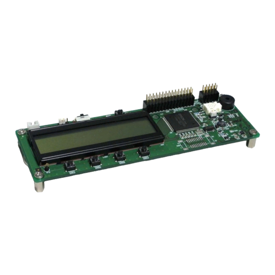
S1C6F632 sensor LCD panel (6) Expansion connector implementation pattern Figure 2.1.1 Names of components mounted on the upper side of S5U1C6F632T1 (3) Coin cell holder Figure 2.1.2 Names of components mounted on the underside of the S5U1C6F632T1 EPSON S5U1C6F632T1/T2 (SVT6F632) Hardware Manual... - Page 10 (1) ICE connectors (LCD) (2) Reset switch (3) Expansion connector Piezo buzzer Pressure sensor Illumination sensor LCD panel Push-on switches (3) Expansion connector implementation pattern Figure 2.1.3 Names of components mounted on the upper side of S5U1C6F632T2 EPSON S5U1C6F632T1/T2 (SVT6F632) Hardware Manual...
-
Page 11: Component Functions
(1) Power supply input selector switch This jumper switch (JP2) is used to select the method of power supply. The S5U1C6F632T1 board can operate on a coin cell or external power supply. When a coin cell is used, set this switch to “B.” To use an external power source, set the switch to “E.”... - Page 12 Press this switch to initialize the peripheral devices for the board and to provide an initialization signal to the connected ICE63. (3) Expansion connector, expansion connector implementation pattern These are used to connect custom client boards for expanded functionality. For more information, refer to “12. External Interface.” EPSON S5U1C6F632T1/T2 (SVT6F632) Hardware Manual...
-
Page 13: Board Dimensional Diagram
2. Component Names and Functions 2.3 Board dimensional diagram 2.3.1 Board dimensions The dimensions of the boards are given below. S5U1C6F632T1/T2 Figure 2.3.1 S5U1C6F632T1 board dimensions S5U1C6F632T2 (interface board) Component coordinate origin Figure 2.3.2 S5U1C6F632T2 interface board dimensions * Note ... -
Page 14: Lcd Panel Dimensions
2. Component Names and Functions 2.3.2 LCD panel dimensions The dimensions of the LCD panel mounted on the board are given below. Figure 2.3.3 (a) LCD panel/bezel dimensions EPSON S5U1C6F632T1/T2 (SVT6F632) Hardware Manual... - Page 15 2. Component Names and Functions Figure 2.3.3 (b) LCD panel dimensions Figure 2.3.3 (c) Bezel dimensions EPSON S5U1C6F632T1/T2 (SVT6F632) Hardware Manual...
-
Page 16: Main Components
2. Component Names and Functions 2.4 Main components S5U1C6F632T1 CPU (U1)......................S1C6F632 (Seiko Epson) Crystal oscillator 32.768 kHz (x 1)..............MC-306 (Epson Toyocom) Ceramic oscillator (x 2) ..................EFOSS4004E5 (Matsushita) LCD (LCD1)...................... Custom-made component Thermistor (R7) ....................103KT1005 (Ishizuka) Humidity sensor (R3) .................. -
Page 17: Block Diagram
SEN1 OSC1 Crystal oscillator Power switch (32.768 Hz) (slide switch) Piezo buzzer OSC2 OSC3 Ceramic oscillator Expansion (4 MHz) connector OSC4 Cable for writer USB-Serial on Board Writer S5U1C88000W4 Figure 3.1 S5U1C6F632T1 block diagram EPSON S5U1C6F632T1/T2 (SVT6F632) Hardware Manual... - Page 18 SCP1000 Push-on switches Piezo buzzer Expansion connector ICE interfaces 1) 40 pins x 2: I/O1 2) 10 pins x 1: I/O2 3) 40 pins x 2: LCD In-circuit emulator S5U1C63000H Figure 3.2 S5U1C6F632T2 block diagram EPSON S5U1C6F632T1/T2 (SVT6F632) Hardware Manual...
-
Page 19: Operating Configuration And Startup Procedure
With the USB-Serial on Board Writer (S5U1C88000W4) connected, the S5U1C6F632T1 can write programs/data to the internal flash EEPROM of the S1C6F632 mounted on the S5U1C6F632T1 board. Once a program/data is written, the board can run from a coin cell for standalone operations. The corresponding connection configurations and startup procedures are described below. -
Page 20: In-Circuit Emulator Debugging Operations (S5U1C6F632T2)
Caution! The sensors (temperature sensor, humidity sensor) for R/F converter use variable resistors in pseudo mode. Mount variable resistors and other components to the in-circuit emulator’s internal add-on board (S5U1C6F632P2) for S1C6F632 for software evaluations. EPSON S5U1C6F632T1/T2 (SVT6F632) Hardware Manual... -
Page 21: Connecting The Ports To Peripheral Circuits
PD pin for pressure sensor (SCP1000) (after logic inversion) Expansion connector (CN2) ICE connector (CN5 P2) Programmable P31/TOUT_B DRDY pin for pressure sensor (SCP1000) timer Expansion connector (CN2) ICE connector (CN5 P4 P2) EPSON S5U1C6F632T1/T2 (SVT6F632) Hardware Manual... - Page 22 ICE connector (CN5 P4 P2) Expansion connector (CN2) Expansion connector (CN3) ICE connector (CN5 P4 P2) Caution! Connect by shorting out the solder bridge. In the case of S5U1C6F632T2 Connector not provided. Board pattern only. EPSON S5U1C6F632T1/T2 (SVT6F632) Hardware Manual...
-
Page 23: Switch Input (Shared Input/Output Ports)
It changes to High (input = 1) when the push-on switch is pressed. Caution! The mask option specification for the S1C6F632 of the board is Standard Type B. For more information, refer to the S1C6F632 Technical Manual. EPSON S5U1C6F632T1/T2 (SVT6F632) Hardware Manual... -
Page 24: Temperature/Humidity Measurement (R/F Converter)
7. Temperature/Humidity Measurement (R/F Converter) The S5U1C6F632T1 is equipped with a temperature sensor (thermistor resistor) and a humidity sensor. Using the S1C6F632’s internal R/F converter, the S5U1C6F632T1 can measure temperature and humidity. The S5U1C6F632T2 lacks the resistor or capacitor necessary for such measurements. For software evaluations, variable resistors and other functions are connected in pseudo mode to the platform on the add-on board (S5U1C6F632P2), which is designed to be used in combination with the ICE63. -
Page 25: Lcd Display (Lcd Driver)
48 segments (SEG) x 32 commons (COM). On the SVT6F632, the display area is centered in the LCD panel, as shown below. SEG direction LCD panel display area Figure 8.2 SEG/COM direction of LCD panel EPSON S5U1C6F632T1/T2 (SVT6F632) Hardware Manual... -
Page 26: Pressure Sensor (Serial Interface)
ICE connector (CN5 P4 P2) SS (P23) CSB pin for pressure sensor (SCP1000) (after logic inversion) Expansion connector (CN2) ICE connector (CN5 P4 P2) Connector not provided. Board pattern only. In the case of S5U1C6F632T2 EPSON S5U1C6F632T1/T2 (SVT6F632) Hardware Manual... - Page 27 9. Pressure Sensor (Serial Interface) Pressure sensor S1C6F632 Figure 9.1 Pressure sensor connection diagram EPSON S5U1C6F632T1/T2 (SVT6F632) Hardware Manual...
-
Page 28: Buzzer (Sound Generator)
10. Buzzer (Sound Generator) 10. Buzzer (Sound Generator) The SVT6F632 can drive a piezo buzzer using the S1C6F632’s built-in sound generator. This capability is enhanced by the externally connected transistor. S1C6F632 Figure 10.1 Piezo buzzer drive circuit diagram EPSON S5U1C6F632T1/T2 (SVT6F632) Hardware Manual... -
Page 29: Illumination Sensor
The S1C6F632 uses the shared input/output ports (P40 to P42) to control the AD converter. It also uses the shared input/output port (P33) to control the illumination sensor power supply. S1C6F632 Illumination sensor Figure 11.1 Illumination sensor circuit diagram EPSON S5U1C6F632T1/T2 (SVT6F632) Hardware Manual... -
Page 30: External Interface
Solder bridge R/F converter Piezo buzzer Buzzer circuit Push-on switches Input/output circuit Pressure sensor Serial interface Illumination sensor AD converter DMOD USB-Serial DRXD on Board DTXD Writer DCLK Figure 12.1 External interface connector (S5U1C6F632T1) EPSON S5U1C6F632T1/T2 (SVT6F632) Hardware Manual... - Page 31 S5U1C6F632T2 external interface connector Interface board Main board Thermistor resistor for temperature S1C6F632 measurement Solder bridge (Not mounted) Piezo buzzer Push-on switches Pressure sensor Illumination sensor AD converter Figure 12.2 External interface connector (S5U1C6F632T2) EPSON S5U1C6F632T1/T2 (SVT6F632) Hardware Manual...
-
Page 32: Usb-Serial On Board Writer (S5U1C88000W4) Connector (Cn1)
Power supply pin (positive) DCLK System clock input Power supply pin (negative) DTXD Serial interface data output DRXD Serial interface data input RESET Reset input Not connected Power supply pin (negative) DMOD Programming mode setting input EPSON S5U1C6F632T1/T2 (SVT6F632) Hardware Manual... -
Page 33: Expansion Connector (Cn2)
RESET Reset output (positive logic) Power supply pin (negative) Power supply pin (negative) Power supply pin (negative) May be used only with the S5U1C6F632T2. (Cannot be used with R/F converter ch0.) Not connected with S5U1C6F632T1. EPSON S5U1C6F632T1/T2 (SVT6F632) Hardware Manual... -
Page 34: Expansion Connector Implementation Pattern (Cn3)
General-purpose port Power supply pin (negative) General-purpose port Power supply pin (negative) General-purpose port Power supply pin (negative) XRESET Reset output (negative logic) General-purpose port Not connected Power supply pin (positive) Power supply pin (positive) EPSON S5U1C6F632T1/T2 (SVT6F632) Hardware Manual... -
Page 35: Ice Connector (S5U1C6F632T2)
Table 12.4.1 ICE connector pin layout and connector diagram (P1, P2, P3, P5, P6) P1, P2, P3, P5, and P6 connectors Manufacturer: 3M Models: 3432-6002LCPL (P1, P2, P5, P6) (CN4-2) (CN1-2) 3662-6002LCPL (P3) (CN1-1) (CN4-1) (CN3) mounted2 (Upper side) EPSON S5U1C6F632T1/T2 (SVT6F632) Hardware Manual... - Page 36 Not connected Power supply pin (negative) Power supply pin (negative) Not connected Not connected Not connected Not connected Not connected RESET Reset output to ICE (positive logic) Power supply pin (negative) Power supply pin (negative) EPSON S5U1C6F632T1/T2 (SVT6F632) Hardware Manual...
- Page 37 Power supply pin (negative) General-purpose port General-purpose port General-purpose port General-purpose port Not connected Not connected Power supply pin (negative) Power supply pin (negative) May be used by pulling out from the CN2 connector on the main board. EPSON S5U1C6F632T1/T2 (SVT6F632) Hardware Manual...
- Page 38 Power supply pin (positive) Power supply pin (positive) General-purpose port General-purpose port General-purpose port Buzzer Power supply pin (negative) Power supply pin (negative) May be used by pulling out from the CN2 connector on the main board. EPSON S5U1C6F632T1/T2 (SVT6F632) Hardware Manual...
- Page 39 LCD drive waveform input (COM) COM20 LCD drive waveform input (COM) COM19 LCD drive waveform input (COM) COM18 LCD drive waveform input (COM) COM17 LCD drive waveform input (COM) COM16 LCD drive waveform input (COM) EPSON S5U1C6F632T1/T2 (SVT6F632) Hardware Manual...
- Page 40 LCD drive waveform input (SEG) SEG19 LCD drive waveform input (SEG) SEG20 LCD drive waveform input (SEG) SEG21 LCD drive waveform input (SEG) SEG22 LCD drive waveform input (SEG) SEG23 LCD drive waveform input (SEG) EPSON S5U1C6F632T1/T2 (SVT6F632) Hardware Manual...
-
Page 41: Appendix A Consumption Current Measurement Method
Measurement Method The S5U1C6F632T1 board can measure the current consumed solely by the S1C6F632. Figure A.1 shows the circuit structure of the S5U1C6F632T1 board power supply connection. To measure the amount of current consumed just by the S1C6F632, remove the jumper switch (JP1) and connect an ammeter to the two pins in series. - Page 42 COM0 COM1 COM2 COM3 COM4 LCD1 LCD1 COM5 COM6 COM7 COM16 COM7 COM16 COM7 COM6 COM6 COM17 COM17 COM8 COM5 COM5 COM18 COM18 COM9 COM4 COM19 COM4 COM19 COM10 COM3 COM20 COM3 COM20 COM11 COM2 COM2 COM21 COM21 COM12 COM1 COM22 COM1 COM22...
- Page 43 VDD_F SSM3J02F SSM3J02F HIF3E-30PA-2.54DSA HIF3E-30PA-2.54DSA HIF3E-10PA-2.54DSA HIF3E-10PA-2.54DSA DCLK CLK_M 200K 200K FlashWriter DTXD DRXD RESET MRESET VDDFON AD7466 AD7466 DMOD DMOD VDD_F RESET Illumination SDAT VDD_F Expansion I/O SCLK 0.1uF 0.1uF R13 200K R13 200K PAD8 PAD8 0.1uF 0.1uF 0.1uF 0.1uF OPA2349 OPA2349...
- Page 44 CN1-2 CN1-1 CN 3 AXN1500115S AXN1500115S 3662-6002LC 3662-6002LC RESET RESET 3432-6002LC 3432-6002LC 3432-6002LC 3432-6002LC CN4-2 CN4-1 COM1 COM0 SEG24 SEG25 COM2 COM3 SEG26 SEG27 COM4 COM5 SEG29 COM7 SEG28 COM6 SEG31 COM9 SEG30 COM8 SEG32 SEG33 COM10 COM11 COM16SEG63 COM7 SEG34 SEG35 COM12...
- Page 45 Analog devices Illumination sensor TPS856 Toshiba Pressure sensor SCP1000-D01 Inverter U6,U7 SN74LVC2G04DCKT T.I. Regulator LT1962EMS8-3 LINEAR Resonator 32.768KHz MC-306 EPSON TOYOCOM Resistor RK73H2ATTD1005F Resistor 4.3K RK73H2ATTD4301F Screw FB-0305N Wilco Stud 10mm ASB-310E HIROSUGI Dip short plug socket DSP01-002-430G-9 Connector XHP-2 J.S.T...
- Page 46 S5U1C6F632T2100 parts list REV1.0 REVISION/QUANTITY REV. MATERIAL PARTS NAME STANDARD MODEL No. MAKER MARK LOCATION Board SA-0804 Custom Piezo buzzer PS1240P02AT Connector (pin header) HIF3E-30PA-2.54DSA(71) HIROSE Connector AXN1800115S Panasonic Connector AXN1500115S Panasonic Monolithic ceramic capacitor C4,C22,C24,C27,C29,C30 0.1uF 2*1.25 GRM219F11H104ZA01D Murata Tantalum capacitor C26,C28 0.47uF/35V 3.2*1.6...
- Page 47 20/F, Harbour Centre, 25 Harbour Road, Wanchai, Hong Kong Phone: +852-2585-4600 FAX: +852-2827-4346 Telex: 65542 EPSCO HX EPSON TAIWAN TECHNOLOGY & TRADING LTD. 14F, No. 7, Song Ren Road, Taipei 110, TAIWAN Phone: +886-2-8786-6688 FAX: +886-2-8786-6660 EPSON SINGAPORE PTE., LTD.
- Page 48 S5U1C6F632T1/T2 (SVT6F632) Hardware Manual SEMICONDUCTOR OPERATIONS DIVISION EPSON Electronic Devices Website Document code: 411665301 First Issue March 2009 in JAPAN Revised February 2010 in JAPAN...