Behringer ULTRADRIVE PRO DCX2496 User Manual
Hide thumbs
Also See for ULTRADRIVE PRO DCX2496:
- User manual (36 pages) ,
- Sync manual (28 pages) ,
- Software manual (27 pages)

Related Manuals for Behringer ULTRADRIVE PRO DCX2496


Summary of Contents for Behringer ULTRADRIVE PRO DCX2496
- Page 1 All manuals and user guides at all-guides.com User’s Manual...
- Page 2 All manuals and user guides at all-guides.com ULTRADRIVE PRO DCX2496 IMPORTANT SAFETY INSTRUCTIONS...
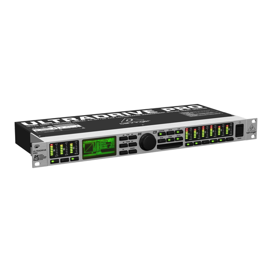
- Page 3 All manuals and user guides at all-guides.com ULTRADRIVE PRO DCX2496 ULTRADRIVE PRO Ultra High-Precision Digital 24-Bit/96 kHz Loudspeaker Management System ®...
- Page 4 All manuals and user guides at all-guides.com ULTRADRIVE PRO DCX2496...
- Page 5 All manuals and user guides at all-guides.com ULTRADRIVE PRO DCX2496...
-
Page 6: Table Of Contents
All manuals and user guides at all-guides.com ULTRADRIVE PRO DCX2496 FOREWORD TABLE OF CONTENTS 1. INTRODUCTION ............7 2. CONTROL ELEMENTS ..........7 3. QUICK START ............9 4. MENU STRUCTURE AND EDITING ....... 10 5. AUDIO CONNECTIONS .......... 20 6. -
Page 7: Introduction
All manuals and user guides at all-guides.com ULTRADRIVE PRO DCX2496 2. CONTROL ELEMENTS 1. INTRODUCTION Fig. 2.1: Input LEDs and display CLIP MUTE 1.1.1 Shipment 1.1.2 Initial operation Fig. 2.2: Menu buttons and data wheel COMPARE PAGE PARAM 1.1.3 Warranty... - Page 8 All manuals and user guides at all-guides.com ULTRADRIVE PRO DCX2496 Fig. 2.5: Output connectors Fig. 2.3: Output LEDs CLIP Fig. 2.6: Input connectors LIMIT MUTE Fig. 2.4: Mains connector and RS-232/RS-485 interface FUSE HOLDER TERM...
-
Page 9: Quick Start
All manuals and user guides at all-guides.com ULTRADRIVE PRO DCX2496 3. QUICK START Fig. 3.3: Mute ß Select Fig. 3.1: Setup ß In/Out Fig.: 3.5: Store ß Internal/Card Fig. 3.2: Out ß X-Over Points Fig. 3.6: Recall ß Internal/Card... -
Page 10: Menu Structure And Editing
All manuals and user guides at all-guides.com ULTRADRIVE PRO DCX2496 4. MENU STRUCTURE AND EDITING ß Fig. 4.2: Output configuration Fig. 4.3: Setup ß In/Out 4.2.1 IN/OUT 1. MONO (no stereo links) Fig. 4.1: Setup ß In/Out Fig. 4.4: Output configuration MONO... - Page 11 All manuals and user guides at all-guides.com ULTRADRIVE PRO DCX2496 2. L(1) M(2) H(3) L(4) M(5) H(6) Fig. 4.5: Output configuration LMHLMH 3. L(1) L(2) M(3) M(4) H(5) H(6) Fig. 4.6: Output configuration LLMMHH 4. L(1) H(2) L(3) H (4) L(5) H(6) Fig.
- Page 12 All manuals and user guides at all-guides.com ULTRADRIVE PRO DCX2496 Fig. 4.9: Setup ß In/Out Fig. 4.12: Setup ß Dly-Corr./Auto-Align Fig. 4.10: Setup ß In/Out Fig. 4.13: Setup ß Dly-Corr./Auto-Align Tab. 4.2: In Stereo Link 4.2.2 DLY-CORR./AUTO-ALIGN Fig. 4.14: Setup ß Dly-Corr./Auto-Align Fig.
- Page 13 All manuals and user guides at all-guides.com ULTRADRIVE PRO DCX2496 Fig. 4.20: Setup ß Page Lock Fig. 4.16: Setup ß Copy Fig. 4.21: Setup ß Page Lock Fig. 4.17: Setup ß Copy Fig. 4.18: Setup ß Copy 4.2.4 PAGE LOCK 4.2.5 GLOBAL LOCK...
- Page 14 All manuals and user guides at all-guides.com ULTRADRIVE PRO DCX2496 Fig. 4.22: Setup ß Global Lock Fig. 4.26: PC (RS-232) mode 2. LINK (RS-485) Fig. 4.23: Setup ß Global Lock Fig. 4.27: Setup ß Miscellaneous 4.2.6 MISCELLANEOUS Fig. 4.24: Setup ß Miscellaneous Fig.
- Page 15 All manuals and user guides at all-guides.com ULTRADRIVE PRO DCX2496 Fig. 4.31: In A ß Gain 4.3.2 DELAY/NAME Fig. 4.30: PC -> LINK mode Fig. 4.32: In A ß Delay/Name 4.3.3 EQ Fig.4 .33: In A ß EQ 4.3.1 GAIN...
- Page 16 All manuals and user guides at all-guides.com ULTRADRIVE PRO DCX2496 Fig. 4.35: In A ß Dynamic EQ (ß Dynamics) 4.3.4 DYNAMIC EQ (FILTER) Tab. 4.3: Band-pass settings with extreme values (results in fig. 4.36) Fig. 4.34: In A ß Dynamic EQ (ß Filter) Fig.
- Page 17 All manuals and user guides at all-guides.com ULTRADRIVE PRO DCX2496 4.4.1 INPUT/GAIN Fig. 4.37: Sum ß Input/Gain Tab. 4.4: Default output names, depending on output configuration 4.5.2 X-OVER POINTS Fig. 4.39: Out 5 ß X-Over Points left right 4.5.1 GENERAL...
- Page 18 All manuals and user guides at all-guides.com ULTRADRIVE PRO DCX2496 Fig. 4.40: Out 5 ß Limiter Fig. 4.43: Mute ß Select 4.5.4 POLARITY/PHASE Fig. 4.41: Out 5 ß Polarity/Phase 4.5.5 DELAY Fig. 4.42: Out 5 ß Delay Fig. 4.44: Recall ß Internal/Card...
- Page 19 All manuals and user guides at all-guides.com ULTRADRIVE PRO DCX2496 AUTO-STORE 4.8.2 DELETE/FORMAT Fig. 4.49: Store ß Delete/Format 4.8.1 INTERNAL/CARD Fig. 4.50: Store ß Delete/Format Fig. 4.46: Store ß Internal/Card Fig. 4.51: Store ß Delete/Format Fig. 4.47: Store ß Internal/Card Fig.
-
Page 20: Audio Connections
All manuals and user guides at all-guides.com ULTRADRIVE PRO DCX2496 Fig. 4.53: Store ß Delete/Format Fig. 4.57: Store ß Copy 4.8.3 COPY 4.8.4 PRESET-LOCK Fig. 4.58: Store ß Preset-Lock Fig. 4.54: Store ß Copy 5. AUDIO CONNECTIONS Fig. 4.55: Store ß Copy Fig. -
Page 21: Applications
All manuals and user guides at all-guides.com ULTRADRIVE PRO DCX2496 6. APPLICATIONS... - Page 22 All manuals and user guides at all-guides.com ULTRADRIVE PRO DCX2496 Fig. 6.1: Stereo 3-way operation...
- Page 23 All manuals and user guides at all-guides.com ULTRADRIVE PRO DCX2496 Fig. 6.2: Stereo 2-way operation plus subwoofer...
- Page 24 All manuals and user guides at all-guides.com ULTRADRIVE PRO DCX2496 Fig 6.3: 3x2-way operation [LCR/Triple Bi-Amping]...
- Page 25 All manuals and user guides at all-guides.com ULTRADRIVE PRO DCX2496 Fig. 6.4: Stereo operation plus mono subwoofer...
- Page 26 All manuals and user guides at all-guides.com ULTRADRIVE PRO DCX2496 Fig. 6.5: Stereo operation plus 2 woofer cabinets...
- Page 27 All manuals and user guides at all-guides.com ULTRADRIVE PRO DCX2496 Fig. 6.6: Stereo 2-way operation plus subwoofer and additional monitor...
- Page 28 All manuals and user guides at all-guides.com ULTRADRIVE PRO DCX2496 Fig. 6.7: Mono 6-way “Zoning” (signal distribution mode)
- Page 29 All manuals and user guides at all-guides.com ULTRADRIVE PRO DCX2496 Fig. 6.8: Triple stereo delay line...
- Page 30 All manuals and user guides at all-guides.com ULTRADRIVE PRO DCX2496 Fig. 6.9: Surround 3.0 ®...
- Page 31 All manuals and user guides at all-guides.com ULTRADRIVE PRO DCX2496 Fig. 6.10: 4-way mono-bridged operation plus 2 monitors (per stereo side)
- Page 32 All manuals and user guides at all-guides.com ULTRADRIVE PRO DCX2496 Fig. 6.11: 5-way mono operation plus 1 additional mono signal (per stereo side)
- Page 33 All manuals and user guides at all-guides.com ULTRADRIVE PRO DCX2496 Fig. 6.12: Surround 5.1...
-
Page 34: Specifications
ß ß ß ® ® BEHRINGER makes every effort to ensure the highest standard of quality. Necessary modifications are carried out without notice. Thus, the specifications and design of the device may differ from the information given in this manual. -
Page 35: Warranty
All manuals and user guides at all-guides.com ULTRADRIVE PRO DCX2496 8. WARRANTY ®...