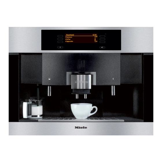
Miele CVA 4075 Technical Information
Coffee systems
Hide thumbs
Also See for CVA 4075:
- Operating and installation instructions (64 pages) ,
- Product dimensions (3 pages) ,
- Installation instructions manual (7 pages)

Related Manuals for Miele CVA 4075


Summary of Contents for Miele CVA 4075
- Page 1 CVA4070 / CVA4075 Coffee Systems Technical Information TECHNICAL INFORMATION CVA4070 / CVA4075 Coffee System © 2007 Miele USA...
-
Page 2: Table Of Contents
CVA4070 / CVA4075 Coffee Systems Technical Information CVA4070 / CVA4075 - Table of Contents Warning and Safety Instructions ............8 Construction and Design...............10 Appliance Overview ..................... 10 1.1.1 Front View ....................10 1.1.2 Interior (Front of Appliance Opened) ............11 Technical Data..................... 12 1.2.1 Electrical Information ................ - Page 3 CVA4070 / CVA4075 Coffee Systems Technical Information CVA4070 / CVA 4075 - Table of Contents (continued) 4.3.6 Brew unit drive, drain position ..............36 Water paths ......................37 4.4.1 General view................... 37 4.4.2 Water path – Making coffee..............38 4.4.3 Water path –...
- Page 4 CVA4070 / CVA4075 Coffee Systems Technical Information CVA4070 / CVA 4075 - Table of Contents (continued) 6.1.19 Appliance variant – Set................. 117 6.1.20 Descale lock – Reset................118 6.1.21 Cleaning lock – Reset................119 Service mode overview..................120 Fault Codes – Read, save and delete ............... 125 6.3.1...
- Page 5 CVA4070 / CVA4075 Coffee Systems Technical Information CVA4070 / CVA4075 - List of Figures Figure 1-1: CVA4070 Front Overview ................10 Figure 1-2: CVA4070 Inside Overview................11 Figure 1-3: CVA4070 Layout Components ..............16 Figure 2-1: CVA4070 Plumbing ..................17 Figure 2-2: CVA4070 Adjusting Feet ................
- Page 6 CVA4070 / CVA4075 Coffee Systems Technical Information CVA4070 / CVA4075 - List of Figures (continued) Figure 5-14: CVA4070 Service Door Retaining Screw Removal ........54 Figure 5-15: CVA4070 Microswitch Removal ..............55 Figure 5-16: CVA4070 Grinder Screw Removal ............. 56 Figure 5-17: CVA4070 Grinder Unit Removal..............
- Page 7 CVA4070 / CVA4075 Coffee Systems Technical Information CVA4070 / CVA 4080 - List of Tables Table 1-1: Technical Data (Continued on Table 1-2) ............ 12 Table 1-2: Technical Data (Cont. from Table 1-1, Cont. on Table 1-3)......13 Table 1-3: Technical Data (Continued from Table 1-2)..........14 Table 1-4: CVA4070 Electrical ..................
-
Page 8: Warning And Safety Instructions
CVA4070 / CVA4075 Coffee Systems Technical Information Warning and Safety Instructions General All repairs should be performed by a trained technician in strict accordance with national, state and local codes. Any repairs or maintenance performed by unqualified personnel could be dangerous. When servicing, modifying, testing or maintaining appliances, all applicable laws, regulations and accident prevention guidelines must be observed. - Page 9 CVA4070 / CVA4075 Coffee Systems Technical Information Touch current measurement Note Touch current measurement should be carried out on all accessible conductive parts that are not connected to ground. Warning! Touch current measurement may only be performed after the ground connection of the unit being tested has been checked and found to be satisfactory! A defective appliance, as well as accessible conductive parts that are not...
-
Page 10: Construction And Design
CVA4070 / CVA4075 Coffee Systems Technical Information Construction and Design Appliance Overview 1.1.1 Front View Figure 1-1: CVA4070 - Front Overview... -
Page 11: Interior (Front Of Appliance Opened)
CVA4070 / CVA4075 Coffee Systems Technical Information 1.1.2 Interior (Front of Appliance Opened) Figure 1-2: CVA4070 - Inside Overview... -
Page 12: Technical Data
CVA4070 / CVA4075 Coffee Systems Technical Information Technical Data ▪ The CVA4070 is designed to be built into cabinets and must be fully installed before any operation. ▪ This appliance can be installed above another appliance but, there must be a solid, closed shelf between the base of the coffee machine and the top of the appliance below ▪... -
Page 13: Table 1-2: Technical Data (Cont. From Table 1-1, Cont. On Table 1-3)
CVA4070 / CVA4075 Coffee Systems Technical Information Model CVA4070, CVA4075 Equipment Water tank Liters Removable coffee bean container Capacity Waste container Portions approx. 25 Drip tray with spill guard grid for secure transport Height adjustable coffee spouts, 5.5 – 9.5 adjustable to cup height Hot water jet Flowstable magnetic piston pump... -
Page 14: Table 1-3: Technical Data (Continued From Table 1-2)
CVA4070 / CVA4075 Coffee Systems Technical Information Model CVA4070,CVA4075 Accessories supplied Kettle-type socket Milk container and attachment for preparing cappucino Descaling and cleaning agents Spoon for ground coffee Optional accessories available Combination strip HKL 60: Combination strip for use in any combination of oven (60 cm), compact oven, or steam oven and coffee maker. -
Page 15: Electrical Information
CVA4070 / CVA4075 Coffee Systems Technical Information 1.2.1 Electrical Information Electrical Model Number Plug Style Requirements CVA4070 120 VAC 15amp NEMA 5-15 Table 1-4: CVA4070 Electrical 1.2.2 Plumbing Information None – not applicable... -
Page 16: Layout Of Components
CVA4070 / CVA4075 Coffee Systems Technical Information Layout of Components 1 Reed contact– ground coffee funnel 17 Flow meter 2 Power electronic EPL 18 Steam pump with temperature limiter 3 Light barrier – coffee bean container 19 Coffee/hot water pump with temperature limiter 4 Grinder 20 Solenoid –... -
Page 17: Installation
CVA4070 / CVA4075 Coffee Systems Technical Information Installation Product Dimensions Figure 2-1: CVA4070 - Plumbing... -
Page 18: Installation Procedure
CVA4070 / CVA4075 Coffee Systems Technical Information Installation Procedure Note: Make sure power is not supplied to the appliance while installation or maintenance work is preformed. Disconnect the power supply to the work area by unplugging the unit, tripping the circuit breaker. The coffee system must be installed into cabinetry before being used. -
Page 19: Figure 2-3: Cva4070 Mounting Locations
CVA4070 / CVA4075 Coffee Systems Technical Information If your cabinet has 3/4" (19 mm) side walls, drill four holes for the mounting. 3. Center the unit and Make centers of mounting holes. 4. Take the unit of the niche and drill four holes at the screws markings (1/16"... -
Page 20: Commission And Operation
CVA4070 / CVA4075 Coffee Systems Technical Information Commission and Operation General Operation 3.1.1 Touch Controls Select a touch control with your fingertip to use the machine 3.1.2 Display To select a menu, select the touch control next to the respective menu point. -
Page 21: Turning On
CVA4070 / CVA4075 Coffee Systems Technical Information 3.1.4 Turning On 1. Select "On/Off" to turn the coffee system on. • The display shows the clock. See "Settings - Clock - Setting the time of day" to set the time. • During the very first use, you will be prompted to select a language. - Page 22 CVA4070 / CVA4075 Coffee Systems Technical Information Language Settings To show the displays in the desired language, select the language before the first use. 1. Select "Settings" from the main menu during the pre-heating phase or 2. in the main menu. 3.
-
Page 23: Setting The Time Of Day
CVA4070 / CVA4075 Coffee Systems Technical Information Clock Settings 1. Select "Settings". 2. Select "Clock". 3.3.1 Setting the Time of Day 1. Select "Enter Time". 2. Select "+" or "-" with the right touch controls to select the hours. 3. Set the minutes by selecting "Minutes". 4. -
Page 24: Clock Display On/Off
CVA4070 / CVA4075 Coffee Systems Technical Information 3.3.4 Clock Display On/Off The clock can be displayed or turned off. • If the display is turned on, the time of day is displayed when the machine is turned off. • If the option is set off, the display turns off after 60 seconds. 1. -
Page 25: Filling The Beans Container
CVA4070 / CVA4075 Coffee Systems Technical Information Figure 3-2: CVA4070 Pull Water Tank Out. . Pull the water tank out. 3. Fill the container with fres h, cold tap water to the "Max." mark. 4. Close the lid and push the water tank into the unit until it clicks in place. -
Page 26: Filling Ground Coffee
CVA4070 / CVA4075 Coffee Systems Technical Information 2. Push the lid back and fill the container with roasted coffee beans. 3. Push the lid back into place and put the beans container back into the appliance. Close the do Filling Ground Coffee A funnel for ground coffee is pr ovided in case you would like to prepare a different coffee type, e.g. -
Page 27: Adjust The Grinder Setting
CVA4070 / CVA4075 Coffee Systems Technical Information igure 3-7: CVA4070 Dispenser Height 1. Pull the coffee dispenser slowly up or down. Adjust the Grinder Setting Figure 3-8: CVA4070 Grinder Adjustment 1. Push the slide control to the left for a finer grind or to the right for a coarser grind. -
Page 28: Steam System
CVA4070 / CVA4075 Coffee Systems Technical Information Steam System The appliance has two heating systems. That allow for independent preparation of froth/cappuccino or espresso/coffee. The second heat system can be turned off to save energy during the heating phase e.g. if froth is not prepared very often. -
Page 29: Function
The appliance is equipped with an optical interface for diagnostic support and program updates (Figure 4-1, item 1). It can be located with the function “Find optical interface” of the Miele Diagnostic Support. Control Electronic EPX The control electronic is located i n the door (Figure 1-2, Item 8). -
Page 30: Brew Unit Controls
CVA4070 / CVA4075 Coffee Systems Technical Information Brew Unit Controls .3.1 Position of the Microswitches 1 Microswitch grinding amount compensation 2 Microswitch brew unit present 3 Microswitch top position control (home position) 4 Microswitch bottom position control (compressing and drain position) Figure 4-2: CVA4070 Brew Unit he brew unit is controlled by 4 microswitches (Figure 4-2). -
Page 31: Brew Unit Present Control
CVA4070 / CVA4075 Coffee Systems Technical Information .3.2 Brew Unit Present Control If the brew unit is seated, the microswitch brew unit present switches (Figure 4-2, Item 2) will be activated. .3.3 Electronic Grinding Amount Compensation The grinding amount compensation balances out different grinder settings and coffee types. -
Page 32: Table 4-1: Cva4070 Ground Coffee Setting
CVA4070 / CVA4075 Coffee Systems Technical Information During the brewing process, the cams of the brew unit move past the microswitch. (Figure 4-3, Item 2). The farther the cams move, the more ground coffee is in the brew unit. Five positions can be registered: Table 4-1: CVA4070 Ground Coffee Setting 1, 2, 3 Areas of measurable volume 1, 2 and 3 igure 4-4: CVA4070 Brew Unit Volu... -
Page 33: Brew Unit Drive, Home Position
CVA4070 / CVA4075 Coffee Systems Technical Information 1, 2, 3 Volume areas 1, 2 and 3 Figure 4-5: CVA4070 Ground Coffee Volume The ground coffee amount can be measured in three volume areas (Figure 4-4), which correspond to the volume areas at the appliance (Figure 4-5). -
Page 34: Figure 4-7: Cva4070 Front View
CVA4070 / CVA4075 Coffee Systems Technical Information Pawl Figure 4-7: CVA4070 Front View. the brew unit is in the home position, the left cam of the double cam element activates the top microswitch; the bottom microswitch is not switched (Figure 4-6). The pawl is in the home position (Figure 4-7). -
Page 35: Brew Unit Drive, Compressing Position (Brew Position)
CVA4070 / CVA4075 Coffee Systems Technical Information .3.5 Brew Unit Drive, Compressing Position (Brew Position) igure 4-8: CVA4070 Rear View Pawl Figure 4-9: CVA4070 Front View The drive moves until the second cam of the double cam element switches the bottom microswitch, and the top microswitch is no lon switched (Figure 4-8). -
Page 36: Brew Unit Drive, Drain Position
CVA4070 / CVA4075 Coffee Systems Technical Information .3.6 Brew Unit Drive, Drain Position ure 4-10: CVA4070 Rear View Figure 4-11: CVA4070 Front View After the coffee is brewed, the drive moves back until the first cam of the double cam element activates the bottom microswitch and the top microswitch is switched (Figure 4-10). -
Page 37: Water Paths
CVA4070 / CVA4075 Coffee Systems Technical Information Water Paths .4.1 General View 1 Waste container 10 Flow-thru heater coffee/hot water 2 Cappuccinatore 11 Pressure relief valve 3 Water tank reed s witch 12 Hot water solenoid 4 Water tank 13 Drain valve 5 Pressure relie va 14 Brew unit 6 Steam pump... -
Page 38: Water Path - Making Coffee
CVA4070 / CVA4075 Coffee Systems Technical Information .4.2 Water Path – Making Coffee 1 Waste container 11 Pressure relief valve 3 Water tank reed s witch 13 Drain valve 4 Water tank 14 Brew unit 8 Flow meter 17 Coffee dispenser 9 Coffee/hot water pump 18 Drip tray 10 Flow-thru heater coffee/hot wat... -
Page 39: Water Path - Hot Water
CVA4070 / CVA4075 Coffee Systems Technical Information .4.3 Water Path – Hot Water 3 Water tank reed switch 11 Pressure relief valve 4 Water tank 12 Hot water solenoid 8 Flow meter 16 Hot water dispenser 9 Coffee/hot w er pum 18 Drip tray 10 Flow-thru heater coffee/hot wat Figure 4-14: CVA4070 Hot Water Path View... -
Page 40: Water Path - Steam
CVA4070 / CVA4075 Coffee Systems Technical Information .4.4 Water Path – Steam 2 Cappuccinatore 6 Steam pump 3 Water tank reed s witch 7 Flow-thru hea ter steam 4 Water tank 15 Steam solenoid 5 Pressure relie va 18 Drip tray Figure 4-15: CVA4070 Steam Water Path View When “cappuccino”... -
Page 41: Service
CVA4070 / CVA4075 Coffee Systems Technical Information Service Appliance – Remove from Cabinet 1. Open the door of the unit. 2. Empty containers and the d rip tray. 1. Appliance retaining screws Figure 5-1: CVA4070 Service View 3. Remove the screws (Figure 5-1, Item 1). 4. -
Page 42: Door Lamps - Remove
CVA4070 / CVA4075 Coffee Systems Technical Information 5 .2 Door Lamps – Remove . Open the door of the unit. 1 Retaining screws of cover Figure 5-2: CVA4070 Door Lamp Screw Removal 2. Remove the screws (Figure 5-2, Item 1). 3. - Page 43 CVA4070 / CVA4075 Coffee Systems Technical Information igure 5-3: CVA4070 Door Lamp Removal 3. Unclip the lamps and remove them (Figure 5-3).
-
Page 44: Door - Remove
CVA4070 / CVA4075 Coffee Systems Technical Information Door – Remove . Open the door of the unit. 1 Retaining screws right panel Figure 5-4: CVA4070 Door Screw Removal 2. Remove the screws on the right panel (Figure 5-4, Item1). 3. Remove the right panel. -
Page 45: Figure 5-5: Cva4070 Door Retaining Screw Removal
CVA4070 / CVA4075 Coffee Systems Technical Information Figure 5-5: CVA4070 Door Retaining Screw Removal . Unplug the connecting plug at the power electronic. 5. Remove the door retaining screws: • Disconnect the plug to the power electronic (Figure 5-5, Item 1). •... -
Page 46: Hot Water Dispenser - Remove
CVA4070 / CVA4075 Coffee Systems Technical Information Hot Water Dispenser – Remove 1. Open the door of the unit. 1 Retaining screws of cover Figure 5-6: CVA4070 Hot Water Removal 2. Remove the screws of the cover (Figure 5-6, Item1). 3. -
Page 47: Figure 5-7: Cva4070 Hot Water Retaining Screw Removal
CVA4070 / CVA4075 Coffee Systems Technical Information 1 Retaining screws of bracket Figure 5-7: CVA4070 Hot Water Retaining Screw Removal 4. Release the teflon hose from its connection and pull it out (Figure 5-7). Remove the s crews of the bracket (Figure 5-7, Item1). 6. -
Page 48: Cappuccinatore - Remove
CVA4070 / CVA4075 Coffee Systems Technical Information Cappuccinatore – Remove 1. Open the door of the unit. 1 Retaining screws of cover Figure 5-8: CVA4070 Cappuccinatore Screw Removal 2. Remove the screws of the cover (Figure 5-8). 3. Remove the cover. - Page 49 CVA4070 / CVA4075 Coffee Systems Technical Information Retaining screws of bracket CVA4070 Cap puccinatore Retaining Screw Removal Figure 5-9: 4. Release the teflon hose from its connection and pull it out (020 Fig. 6). Remove the s crews of the bracket (Figure 5-9, Item1). 6.
-
Page 50: Brew Unit Drive - Remove
CVA4070 / CVA4075 Coffee Systems Technical Information Brew Unit Drive – Remove 1. Appliance – Remove from ca binet”, (Figure 5-1). 2. Remove the retaining screws of the appliance lid. 3. Take the lid off. 1 Service door retaining screws Figure 5-10: CVA4070 Brew Drive Screw Removal 4. - Page 51 CVA4070 / CVA4075 Coffee Systems Technical Information 1 Microswitch grinding amount compensation 2 Brew unit drive CVA407 0 Brew Unit Drive Removal Figure 5-11: 7. Disconnect the plug of the brew unit drive (Figure 5-11, Item 2). 8. Disconnect the plug (ST4) from the power electronic. 9.
-
Page 52: Figure 5-12: Cva4070 Brew Unit Removal
CVA4070 / CVA4075 Coffee Systems Technical Information Figure 5-12: CVA4070 Brew Unit Removal 11. Release the brew unit and take it out of the appliance (Figure 5-12). -
Page 53: Figure 5-13: Cva4070 Brew Unit Retaining Screw Removal
CVA4070 / CVA4075 Coffee Systems Technical Information 1 Brew unit drive retaining screws Figure 5-13: CVA4070 Brew Unit Retaining Screw Removal 12. Remove the brew unit drive retaining screws (Figure 5-13, Item 1). 13. Take the brew unit drive out toward the rear. Note When installing the brew unit drive, make sure that the pawl is set in the... -
Page 54: Microswitch Grinding Amount Compensation - Remove
CVA4070 / CVA4075 Coffee Systems Technical Information Microswitch Grinding Amount Compensation – Remove 1. Appliance – Remove from cabinet”, (figure 5-1). 2. Remove the retaining screws of the appliance co ver. 3. Remove the cover. 1 Service door retaining screws Figure 5-14: CVA4070 Service Door Retaining Screw Removal 4. - Page 55 CVA4070 / CVA4075 Coffee Systems Technical Information 1 Microswitch grinding amount compensation 2 Brew unit drive igure 5-15: CVA4070 Microswitch Removal 7. Disconnect the plug from the microswitch (Figure 5-15, Item 1). 8. Unclip the microswitch and take it out.
-
Page 56: Grinder - Remove
CVA4070 / CVA4075 Coffee Systems Technical Information Grinder – Remove 1. Appliance – Remo ve from cabinet ( Figure 5.1). 2. Remove the retaining screws of the appliance lid 3. Remove the lid. 1 Service door retaining screws CVA4070 Grinder S crew Removal Figure 5-16: 4. -
Page 57: Figure 5-17: Cva4070 Grinder Unit Removal
CVA4070 / CVA4075 Coffee Systems Technical Information Figure 5-17: CVA4070 Grinder Unit Removal 7. Take the bean container out. -
Page 58: Figure 5-18: Cva4070 Bean Container Screw Removal
CVA4070 / CVA4075 Coffee Systems Technical Information 1 Retaining screws of the bean container base Figure 5-18: CVA4070 Bean Container Screw Removal 8. Remove the retaining screws of the base (Figure 5-18, Item1). -
Page 59: Figure 5-19: Cva4070 Bean Container Removal
CVA4070 / CVA4075 Coffee Systems Technical Information Figure 5-19: CVA4070 Bean Container Removal 9. Pull the handle off the adjustment lever (Figure 5-19). 10. Take the base out. -
Page 60: Figure 5-20: Cva4070 Grinder Retaining Screws Removal
CVA4070 / CVA4075 Coffee Systems Technical Information 1 Grinder retaining screws Figure 5-20: CVA4070 Grinder Retaining Screws Removal 11. Slide the adjustment lever aside (Figure 5-20). 12. Remove the grinder retaining screws (Figure 5-20, Item1). 13. Take the grinder out. 14. -
Page 61: Hot Water Solenoid - Remove
CVA4070 / CVA4075 Coffee Systems Technical Information Hot water Solenoid – Remove 1 Retaining screws of support plate Figure 5-20: CVA4070 Grinder Retaining Screws Removal 1. Remove the screws of the support plate (Figure 5-20, Item 1). 2. Open the support plate. -
Page 62: Figure 5-21: Cva4070 Solenoid Removal
CVA4070 / CVA4075 Coffee Systems Technical Information 1 Steam solenoid 2 Hot water solenoid Figure 5-21: CVA4070 Solenoid Removal... -
Page 63: Figure 5-22: Cva4070 Solenoid Removal
CVA4070 / CVA4075 Coffee Systems Technical Information Figure 5-22: CVA4070 Solenoid Removal 3. Pull out the safety springs at the connection of the hot water solenoid (Figure 5-22). 4. Take the solenoid out. 5. Pull the connecting plug off the solenoid. Warning! To prevent malfunctions in the water system (for example clogging of the valves), never use grease, oil or other lubricants when assembling the... -
Page 64: Steam Solenoid - Remove
CVA4070 / CVA4075 Coffee Systems Technical Information 5.10 Steam Solenoid – Remove 1 Retaining screws of support plate Figure 5-23: CVA4070 Solenoid Screw Removal 1. Remove the screws of the support plate (Figure 5-23, Item1). 2. Open the support plate. -
Page 65: Figure 5-24: Cva4070 Solenoid Removal
CVA4070 / CVA4075 Coffee Systems Technical Information 1 Steam solenoid 2 Hot water solenoid Figure 5-24: CVA4070 Solenoid Removal... -
Page 66: Figure 5-25: Cva4070 Solenoid Removal
CVA4070 / CVA4075 Coffee Systems Technical Information Figure 5-25: CVA4070 Solenoid Removal 3. Pull out the safety springs at the connection of the steam solenoid (Figure 5-25). 4. Remove the solenoid. 5. Pull the connecting plug off the solenoid. Warning! To prevent malfunctions in the water system (for example clogging of the valves), never use grease, oil or other lubricants when assembling the water supplying components. -
Page 67: Flow-Thru Heater Coffee/Hot Water - Remove
CVA4070 / CVA4075 Coffee Systems Technical Information 5.11 Flow-thru Heater Coffee/Hot Water – Remove 1. Appliance – Remove from cabinet”, (Figure 5-1). 2. Remove the cover retaining screws. 3. Remove the cover. 1 Service door retaining screws Figure 5-26: CVA4070 Rear Screw Removal 4. -
Page 68: Figure 5-27: Cva4070 Flow-Thru Heater
CVA4070 / CVA4075 Coffee Systems Technical Information 1 Flow-thru heater steam 2 Flow-thru heater coffee/hot water Figure 5-27: CVA4070 Flow-thru Heater 7. Remove the rear wall retaining screws at the bottom. 8. Take off the lower rear wall. 1 Retaining screws flow-thru heater Figure 5-28: CVA4070 Flow-thru Heater Screw Removal... -
Page 69: Figure 5-29: Cva4070 Flow-Thru Heater Temperature
CVA4070 / CVA4075 Coffee Systems Technical Information 9. Pull out the spring clips at the water connection (Figure 5-28). 10. Remove the mounting platform, shelf screws of the flow-thru heater (Figure 5-28, Item. 1). 11. Remove the flow-thru heater. 1 Temperature limiter 2 Temperature fuse 3 Temperature sensor Figure 5-29: CVA4070 Flow-thru Heater Temperature... -
Page 70: Flow-Thru Heater Steam - Remove
CVA4070 / CVA4075 Coffee Systems Technical Information 5.12 Flow-thru Heater Steam – Remove 1. Appliance – Remove from cabinet”, (Figure 5-1). 2. Remove the retaining screws of the appliance cover. 3. Remove the cover. 1 Service door retaining screws Figure 5-30: CVA4070 Rear Service Door Retaining Screw Removal 4. -
Page 71: Figure 5-31: Cva4070 Flow-Thru Heater Steam
CVA4070 / CVA4075 Coffee Systems Technical Information 1 Flow-thru heater steam 2 Flow-thru heater coffee/hot water Figure 5-31: CVA4070 Flow-thru Heater Steam 1 Retaining screws flow-thru heater Figure 5-32: CVA4070 Flow-thru Heater Steam 7. Pull out the spring clips at the connection (Figure 32). 8. -
Page 72: Figure 5-33: Cva4070 Temperature
CVA4070 / CVA4075 Coffee Systems Technical Information 1 Temperature limiter 2 Temperature sensor 3 Temperature fuse Figure 5-33: CVA4070 Temperature 10. Remove the temperature limiter, temperature sensor and temperature fuse (Figure 5-33, Items 1 – 3). 11. Pull the connectors off the flow-thru heater. Warning! To prevent malfunctions in the water system (for example clogging of the valves), never use grease, oil or other lubricants when assembling the... -
Page 73: Coffee/Hot Water Pump - Remove
CVA4070 / CVA4075 Coffee Systems Technical Information 5.13 Coffee/Hot Water Pump – Remove 1. Appliance – Remove from cabinet”, (Figure 5-1). 2. Remove the cover retaining screws. 3. Remove the cover. 1 Service door retaining screws Figure 5-34: CVA4070 Rear Service Door Screw Removal 4. -
Page 74: Figure 5-35: Cva4070 With Service Door Open
CVA4070 / CVA4075 Coffee Systems Technical Information Figure 5-35: CVA4070 With Service Door Open 7. Remove the rear wall retaining screws at the bottom. 8. Remove the lower wall. -
Page 75: Figure 5-36: Cva4070 Coffee/Hot Water Pump
CVA4070 / CVA4075 Coffee Systems Technical Information 1 Coffee/hot water pump 2 Steam pump Figure 5-36: CVA4070 Coffee/Hot Water Pump... -
Page 76: Figure 5-37: Cva4070 Coffee/Hot Water Pump Removal
CVA4070 / CVA4075 Coffee Systems Technical Information 1 Safety valve 2 Pump retaining screws 3 Temperature limiter Figure 5-37: CVA4070 Coffee/Hot Water Pump Removal 9. Release the teflon hose from the safety valve and disconnect it (Figure 5-37, Item 1). 10. -
Page 77: Steam Pump - Remove
CVA4070 / CVA4075 Coffee Systems Technical Information 5.14 Steam Pump – Remove 1. Appliance – Remove from cabinet”, (Figure 5-1). 2. Remove the cover retaining screws. 3. Remove the cover. 1 Service door retaining screws. Figure 5-38: CVA4070 Service Door Steam Pump Removal 4. -
Page 78: Figure 5-39: Cva4070 Steam Pump Removal
CVA4070 / CVA4075 Coffee Systems Technical Information Figure 5-39: CVA4070 Steam Pump Removal 7. Remove the rear wall retaining screws at the bottom. 8. Remove the lower wall. -
Page 79: Figure 5-40: Cva4070 Coffee/Hot Water Pump Removal
CVA4070 / CVA4075 Coffee Systems Technical Information 1 Coffee/hot water pump 2 Steam pump Figure 5-40: CVA4070 Coffee/Hot Water Pump Removal... -
Page 80: Figure 5-41: Cva4070 Pump Retaining Screws Removal
CVA4070 / CVA4075 Coffee Systems Technical Information 1 Pump retaining screws 2 Temperature limiter Figure 5-41: CVA4070 Pump Retaining Screws Removal 9. Pull the connectors off the pump. 10. Remove the pump bracket retaining screws (Figure 5-41, Item 1). 11. Remove the pump. 12. -
Page 81: Flow Meter - Remove
CVA4070 / CVA4075 Coffee Systems Technical Information 5.15 Flow Meter – Remove 1. Appliance – Remove from cabinet”, (Figure 5-1). 2. Remove the cover retaining screws. 3. Remove the cover. 1 Service door retaining screws. Figure 5-42: CVA4070 Flow Meter Screws Removal 4. -
Page 82: Figure 5-43: Cva4070 Flow Meter Removal
CVA4070 / CVA4075 Coffee Systems Technical Information Figure 5-43: CVA4070 Flow Meter Removal 7. Remove the rear wall retaining screws at the bottom. 8. Remove the lower wall. -
Page 83: Figure 5-44: Cva4070 Flow Meter Removal
CVA4070 / CVA4075 Coffee Systems Technical Information 1 Flow meter Figure 5-44: CVA4070 Flow Meter Removal... -
Page 84: Figure 5-45: Cva4070 Flow Meter Safety Ring Removal
CVA4070 / CVA4075 Coffee Systems Technical Information 1 Flow meter 2 Safety ring Figure 5-45: CVA4070 Flow Meter Safety Ring Removal 9. Pull the silicone hoses off the flow meter (Figure 5-45). 10. Pull the connector off the flow meter. 11. -
Page 85: Power Electronic Epl - Remove
CVA4070 / CVA4075 Coffee Systems Technical Information 5.15 Power Electronic EPL – Remove 1. Appliance – Remove from cabinet”, (Figure 5-1). 2. Remove the rear wall retaining screws at the top. 3. Remove the top rear wall. 1 Power electronic retaining screws Figure 5-46: CVA4070 Power Electronic Retaining Screws Removal 4. -
Page 86: Figure 5-47: Cva4070 Connecting Plugs And Pin Allocations
CVA4070 / CVA4075 Coffee Systems Technical Information Figure 5-47: CVA4070 Connecting Plugs and Pin Allocations. Plug # Pins Usage / Component vacant (solenoid for hard plumbing) Steam solenoid Hot water solenoid Reed contact ground coffee funnel Table 5-1: CVA4070 Connecting Plugs and Pin Allocations (Cont. on Table 5-2) - Page 87 CVA4070 / CVA4075 Coffee Systems Technical Information Plug # Pins Usage / Component Reed contact waste container Transmitter for electronic light barrier bean container Receiver for electronic light barrier bean container Microswitch brew unit 1 compensation Microswitch brew unit 2 clockwise turn Microswitch brew unit 3 counter-clockwise turn Microswitch brew unit 4 present Microswitch brew unit XXXXMasse...
- Page 88 CVA4070 / CVA4075 Coffee Systems Technical Information LED interior lamp Temperature sensor NTC coffee/hot water Temperature sensor NTC steam Flow meter ST10 Connector to main power supply ST11 Connection to Plug 12 Flow-thru heater steam vacant Flow-thru heater coffee/hot water vacant Connection to plug 11 Interference suppressor...
-
Page 89: Fault Diagnosis
CVA4070 / CVA4075 Coffee Systems Technical Information Fault Diagnosis Programming Mode Initial requirements 1. Switch the appliance off. Accessing Note Access has to be completed within 10 seconds. 2. Touch pad Clear and hold it. 3. Touch pad On/Off once. 4. -
Page 90: Table 6-1: Cva4070 Program Mode (Cont. On Table 6-2)
CVA4070 / CVA4075 Coffee Systems Technical Information Factory Position Setting Function Setting Back, without Reset All settings made by the customer (except language) Reset are deleted. All own user profiles are deleted. The fault code memory remains. cestina The language remains, even when the program is reset to dansk factory setting. -
Page 91: Table 6-2: Cva4070 Program Mode (Cont. From Table 6-1; Cont. On Table 6-3)
CVA4070 / CVA4075 Coffee Systems Technical Information Factory Position Setting Function Setting Start at e. g. 7:30 Use the pads +/– to set the desired time. Switch e. g. 0:15 off after Switch e. g. 9:00 off after e. g. 7:30 The unit is switched Settings Timer... -
Page 92: Table 6-3: Cva4070 Program Mode (Cont. From Table 6-2; Cont. On Table 6-4)
CVA4070 / CVA4075 Coffee Systems Technical Information Factory Position Settings Function Setting Minimum = 205 °F (96 °C) (in the flow-thru heater) = 208 °F (98 °C) (in the flow-thru heater) Medium = 212 °F (100 °C) (in Settings Temperature Coffee Medium the flow-thru heater) -
Page 93: Table 6-4: Cva4070 Program Mode (Cont. From Table 6-3; Cont. On Table 6-5)
CVA4070 / CVA4075 Coffee Systems Technical Information Factory Position Settings Function Setting The steam system is switched on. Settings Steam System The steam system is switched off. The lamps of the door and the interior are switched on. Automatic The lamps of the door and the interior are switched off. -
Page 94: Table 6-5: Cva4070 Program Mode (Cont. From Table 6-4; Cont. On Table 6-6)
CVA4070 / CVA4075 Coffee Systems Technical Information Factory Position Settings Function Setting Standard The main menu contains a standard user profile: The settings for the grinding amount, temperature, pre- brewing and portion size correspond to the factory setting. Standard Select Up to 7 The selected user own user... -
Page 95: Table 6-6: Cva4070 Program Mode (Cont. From Table 6-5; Cont. On Table 6-7)
CVA4070 / CVA4075 Coffee Systems Technical Information Factory Position Settings Function Setting Step 1 – Low to High Step 8 Contrast Settings Display Step 1 – Dim to Bright Step 14 Brightness Step 1 - Low to High Volume Step 18 Touch pads emit a Signal tone when they are... -
Page 96: Table 6-7: Cva4070 Program Mode (Cont. From Table 6-6)
CVA4070 / CVA4075 Coffee Systems Technical Information Factory Position Settings Function Setting Available The appliance is hooked-up to plumbing. Customer Appliance Hard Available Service Variant plumbing The appliance Available cannot be hooked- up to plumbing. Back, without lifting the descale lock. -
Page 97: Reset
CVA4070 / CVA4075 Coffee Systems Technical Information 6.1.1 Reset Initial requirements Switch the appliance off. Accessing Note Complete the access within 10 seconds. 1. Touch pad Clear and hold. 2. Touch pad On/Off once. 3. Release pad Clear. 4. Touch pad Clear 5 times and at the 5th time, hold it until the programming mode appears. -
Page 98: Language - Set
CVA4070 / CVA4075 Coffee Systems Technical Information 6.1.2 Language – Set Initial requirements Switch the appliance off. Accessing Note Complete the access within 10 seconds. 1. Touch pad Clear and hold. 2. Touch pad On/Off once. 3. Release pad Clear. 4. -
Page 99: Time - Set
CVA4070 / CVA4075 Coffee Systems Technical Information 6.1.3 Time – Set Initial requirements 1. Switch the appliance off. Accessing Note Complete the access within 10 seconds. 1. Touch pad Clear and hold. 2. Touch pad On/Off once. 3. Release pad Clear. 4. -
Page 100: Timer - Set / Activate
CVA4070 / CVA4075 Coffee Systems Technical Information 6.1.4 Timer – Set / Activate Initial requirements 1. Switch the appliance off. Accessing Note Complete the access within 10 seconds. 1. Touch pad Clear and hold. 2. Touch pad On/Off once. 3. Release pad Clear. 4. -
Page 101: Grinding Amount - Set
CVA4070 / CVA4075 Coffee Systems Technical Information 4.1.5 Grinding Amount – Set Initial requirements 1. Switch the appliance off. Accessing Note Complete the access within 10 seconds. 1. Touch pad Clear and hold. 2. Touch pad On/Off once. 3. Release pad Clear. 4. -
Page 102: Pre-Brewing - Set
CVA4070 / CVA4075 Coffee Systems Technical Information 6.1.6 Pre-brewing – Set Initial requirements Switch the appliance off. Accessing Note Complete the access within 10 seconds. 1. Touch pad Clear and hold. 2. Touch pad On/Off once. 3. Release pad Clear. 4. -
Page 103: Temperatures For Coffee And Hot Water - Set
CVA4070 / CVA4075 Coffee Systems Technical Information 6.1.7 Temperatures for Coffee and Hot Water – Set Initial requirements 1. Switch the appliance off. Accessing Note Complete the access within 10 seconds. 1. Touch pad Clear and hold. 2. Touch pad On/Off once. 3. - Page 104 CVA4070 / CVA4075 Coffee Systems Technical Information Hot water: minimum: Represents 96 °C (in the flow-thru heater). low: Represents 98 °C (in the flow-thru heater). medium: Represents 100 °C (in the flow-thru heater). high: Represents 102 °C (in the flow-thru heater). maximum: Represents 104 °C (in the flow-thru heater).
-
Page 105: Automatic Rinse - On / Off
CVA4070 / CVA4075 Coffee Systems Technical Information 6.1.8 Automatic Rinse – On / Off Initial requirements 1. Switch the appliance off. Accessing Note Complete the access within 10 seconds. 1. Touch pad Clear and hold. 2. Touch pad On/Off once. 3. -
Page 106: Steam System - On / Off
CVA4070 / CVA4075 Coffee Systems Technical Information 6.1.9 Steam System – On / Off Initial requirements 1. Switch the appliance off. Accessing Note Complete the access within 10 seconds. 2. Touch pad Clear and hold. 3. Touch pad On/Off once. 4. -
Page 107: Door And Interior Lighting - Set
CVA4070 / CVA4075 Coffee Systems Technical Information 6.1.10 Door and Interior Lighting – Set Initial requirements Switch the appliance off. Accessing Note Complete the access within 10 seconds. 1. Touch pad Clear and hold. 2. Touch pad On/Off once. 3. Release pad Clear. 4. -
Page 108: Coffee Count - Indicate
CVA4070 / CVA4075 Coffee Systems Technical Information 6.1.11 Coffee Count – Indicate Initial requirements 1. Switch the appliance off. Accessing Note Complete the access within 10 seconds. 1. Touch pad Clear and hold. 2. Touch pad On/Off once. 3. Release pad Clear. 4. -
Page 109: System Lock - Set
CVA4070 / CVA4075 Coffee Systems Technical Information 6.1.12 System Lock – Set Initial requirements 1. Switch the appliance off. Accessing Note Complete the access within 10 seconds. 1. Touch pad Clear and hold. 2. Touch pad On/Off once. 3. Release pad Clear. 4. -
Page 110: Water Hardness - Set
CVA4070 / CVA4075 Coffee Systems Technical Information 6.1.13 Water Hardness – Set Initial requirements 1. Switch the appliance off. Accessing Note Complete the access within 10 seconds. 1. Touch pad Clear and hold. 2. Touch pad On/Off once. 3. Release pad Clear. 4. -
Page 111: User Profile - Set
CVA4070 / CVA4075 Coffee Systems Technical Information 6.1.14 User Profile – Set Initial requirements Switch the appliance off. Accessing Note Complete the access within 10 seconds. 1. Touch pad Clear and hold. 2. Touch pad On/Off once. 3. Release pad Clear. 4. - Page 112 CVA4070 / CVA4075 Coffee Systems Technical Information after dispensing: After each time a beverage is dispensed, the main menu changes to a standard user profile. Factory setting: never. Save and quit Save and back: Touch pad next to OK. End: Touch pad On/Off. Quit (without saving) Touch pad On/Off.
-
Page 113: Display - Set
CVA4070 / CVA4075 Coffee Systems Technical Information 6.1.15 Display – Set Initial requirements Switch the appliance off. Accessing Note Complete the access within 10 seconds. 1. Touch pad Clear and hold. 2. Touch pad On/Off once. 3. Release pad Clear. 4. -
Page 114: Signal Tones - Set
CVA4070 / CVA4075 Coffee Systems Technical Information 6.1.16 Signal Tones – Set Initial requirements 1. Switch the appliance off. Accessing Note Complete the access within 10 seconds. 1. Touch pad Clear and hold. 2. Touch pad On/Off once. 3. Release pad Clear. 4. -
Page 115: Factory Setting - Restore
CVA4070 / CVA4075 Coffee Systems Technical Information 6.1.17 Factory Setting – Restore Initial requirements Switch the appliance off. Accessing Note Complete the access within 10 seconds. 1. Touch pad Clear and hold. 2. Touch pad On/Off once. 3. Release pad Clear. 4. -
Page 116: Restart
CVA4070 / CVA4075 Coffee Systems Technical Information 6.1.18 Restart Initial requirements 1. Switch the appliance off. Accessing Note Complete the access within 10 seconds 1. Touch pad Clear and hold. 2. Touch pad On/Off once. 3. Release pad Clear. 4. Touch pad Clear 5 times and at the 5th time, hold it until the programming mode appears. -
Page 117: Appliance Variant - Set
CVA4070 / CVA4075 Coffee Systems Technical Information 6.1.19 Appliance Variant – Set Initial requirements 1. Switch the appliance off. Accessing Note Complete the access within 10 seconds. 1. Touch pad Clear and hold. 2. Touch pad On/Off once. 3. Release pad Clear. 4. -
Page 118: Descale Lock - Reset
CVA4070 / CVA4075 Coffee Systems Technical Information 6.1.20 Descale Lock – Reset Initial requirements Switch the appliance off. Accessing Note Complete the access within 10 seconds. 1. Touch pad Clear and hold. 2. Touch pad On/Off once. 3. Release pad Clear. 4. -
Page 119: Cleaning Lock - Reset
CVA4070 / CVA4075 Coffee Systems Technical Information 6.1.21 Cleaning Lock – Reset Initial requirements 1. Switch the appliance off. Accessing Note Complete the access within 10 seconds. 1. Touch pad Clear and hold. 2. Touch pad On/Off once. 3. Release pad Clear. 4. -
Page 120: Service Mode Overview
CVA4070 / CVA4075 Coffee Systems Technical Information Service Mode Overview Initial requirements 1. Switch the appliance off. Accessing Note Complete the access within 10 seconds. 1. Touch pad Clear and hold. 2. Touch pad On/Off once. 3. Release pad Clear. 4. -
Page 121: Table 6-9: Cva4070 Service Mode (Cont. From Table 6-8; Cont. On Table 6-10)
CVA4070 / CVA4075 Coffee Systems Technical Information Display / Position Description / Results Activation Open The solenoid for hot water is opened. COMPONENT HOT WATER TEST VALVE The solenoid for hot water is Close closed. The micro switches are tested, and the brew unit is returned to its home position. -
Page 122: Table 6-10: Cva4070 Service Mode (Cont. From Table 6-9; Cont. On Table 6-11)
CVA4070 / CVA4075 Coffee Systems Technical Information Display / Position Description / Results Activation The flow-thru heater coffee/hot water heats. The temperature FLOW–THU indication on the heater goes COMPONENT HEATER increases. TEST WATER The flow-thru heater coffee/hot water is switched off. The flow-thru heater steam FLOW–... -
Page 123: Table 6-11: Cva4070 Service Mode (Cont. From Table 6-10; Cont. On Table 6-12)
CVA4070 / CVA4075 Coffee Systems Technical Information Display / Position Description / Results Activation closed The microswitch top position control is activated. SENSOR BREW UNIT TEST The microswitch top position open control is not activated. The microswitch bottom position closed SENSOR BREW UNIT control is activated. -
Page 124: Table 6-12: Cva4070 Service Mode (Continued From Table 6-11)
CVA4070 / CVA4075 Coffee Systems Technical Information Display / Position Description / Results Activation OPERATING HOURS FLOW–THRU Operating hours of the flow-thru HEATER WATER heater coffee/hot water. FLOW–THRU Operating hours of the flow-thru HEATER STEAM heater steam. ESPRESSOS Number of espressos DISPENSED dispensed. -
Page 125: Fault Codes - Read, Save And Delete
CVA4070 / CVA4075 Coffee Systems Technical Information Fault Codes – Read, Save and Delete 6.3.1 Fault Code Accessing Initial requirements Switch the appliance off. Accessing Note Complete the access within 10 seconds. 1. Touch pad Clear and hold. 2. Touch pad On/Off once. 3. -
Page 126: Fault Code Summary
CVA4070 / CVA4075 Coffee Systems Technical Information 6.3.2 Fault Code Summary Fault Code Fault Description Short circuit temperature sensor NTC coffee/hot water Open circuit temperature sensor NTC coffee/hot water Short circuit temperature sensor NTC steam Open circuit temperature sensor NTC steam No water supply Insufficient water supply... - Page 127 CVA4070 / CVA4075 Coffee Systems Technical Information 6.3.3 Short circuit in the temperature sensor NTC coffee/hot water • Check the connecting cables. • Replace the connecting cables if necessary. • Temperature sensor Flow-thru heater coffee/hot water– Check, 0214.46. • Check the temperature sensor. 6.3.4 Open circuit temperature sensor NTC coffee/hot water •...
-
Page 128: F10
CVA4070 / CVA4075 Coffee Systems Technical Information 6.3.7 Hoses broken, clogged, kinked. • Check the hoses. • Replace the hoses if necessary. Water tank valve jammed, clogged. • Check the water tank valve. • Replace the water tank if necessary. Flow meter defective. -
Page 129: F41
CVA4070 / CVA4075 Coffee Systems Technical Information Pump coffee/hot water defective. • Coffee/hot water pump – Remove • Install a new pump coffee/hot water. 6.3.9 Faulty EEPROM/Wrong data • Control electronic EPX – Remove • Install a new control electronic. 6.3.10 Main power frequency not registered •... -
Page 130: F80 Cause
CVA4070 / CVA4075 Coffee Systems Technical Information Brew unit blocked. • Disconnect the appliance from the main power supply. • Remove any foreign matter. • Clean the affected components Defective microswitch or no continuity in connectors. • Check the connecting cables. •... -
Page 131: F82
CVA4070 / CVA4075 Coffee Systems Technical Information Note To be able to continue using the appliance for the preparation of coffee and hot water until service is performed, the customer can switch the steam system off, refer to Steam system – On/off. •...